GROUP 1 STRUCTURE AND FUNCTION
Bạn đang xem bản rút gọn của tài liệu. Xem và tải ngay bản đầy đủ của tài liệu tại đây (781.57 KB, 40 trang )
SECTION 6 WORK EQUIPMENT
GROUP 1 STRUCTURE AND FUNCTION
1. HYDRAULIC SYSTEM OUTLINE
The loader hydraulic system is a pilot operated, open center system which is supplied with flow from
the fixed displacement main hydraulic pump.
The pilot control system is a low pressure, closed center hydraulic system which is supplied with flow
from the first(Steering) pump.
The loader system components are :
Main pump
Main control valve
Bucket cylinder
Boom cylinders
Pilot supply unit
Remote control valve(Pilot control valve)
Safety valve
The pilot supply unit consists of the pressure reducing valve, relief valve and accumulator.
Flow from the main hydraulic pump not used by the steering system leaves the priority valve EF port.
It flows to the inlet port plate of four blocks type main control valve.
The main control valve is a tandem version spool type, open center valve which routes flow to the
boom, bucket or auxiliary cylinders(Not shown) when the respective spools are shifted.
Flow from the steering pump(The first pump) is routed to the pilot supply unit where the steering
pump outlet pressure is reduced to pilot circuit pressure. The pilot supply unit flow to the remote
control valve.
The remote control valve routed flow to either end of each spool valve section in the main control
valve to control spool stroke.
A accumulator mounted on pilot supply unit supplies a secondary pressure source to operated
remote control valve so the boom can be lowered if the engine is off.
The return circuit for the main hydraulic system have return filter inside the hydraulic tank. The return
filter uses a filter element and a bypass valve. The bypass valve is located in the upside of filter.
6-1
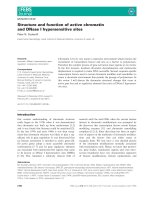
2. HYDRAULIC CIRCUIT
FRONT
REAR
7
8
9
3
B.D/F
LH
RH
LH
B.U
IN
OUT
RH
T
L
P
R
1
5
3
4
2
2
13
a2
2B
2A
14
16
13
24MPa
Boom up
Boom down
b2
12
T
Floating
6
BR1
BR2
1B
M2
P
1A
DS1
Dump
Roll back
S2
a1
S3
P
15
T
b1
24MPa
S1
DS2
24MPa
19.5Mpa
LS
11
F1
21MPa
10
P
T
4
N
P1
3MPa
CF
U
EF
P
P2
LS
17
T
P
C
B
A
1
23
18
A
B
C
1st pump
2nd pump
Brake pump
1
2
3
4
5
6
7
8
22
19
Main pump
Main control valve
Remote control valve
Priority valve
Steering unit
Brake valve
Steering cylinder
Bucket cylinder
F2
20
21
9
10
11
12
13
14
15
16
Boom cylinder
Pilot supply unit
Line filter
Safety valve
Accumulator
Pressure switch
Pressure switch
Pressure switch
6-2
17
18
19
20
21
22
23
Line filter
Air breather
Hydraulic tank
Return filter
By pass valve
Oil cooler(Option)
Check valve(Option)
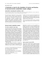
3. WORK EQUIPMENT HYDRAULIC CIRCUIT
8
9
3
B.D/F
LH
B.U
IN
OUT
RH
T
P
1
3
4
2
2
a2
2B
2A
24MPa
Boom up
Boom down
b2
12
T
Floating
1B
P
1A
Dump
a1
A
B
C
b1
24MPa
24MPa
Steering system
1st pump
2nd pump
Brake pump
Roll back
F1
10 P1
21MPa
P
4
F2
11
3MPa
CF
U
EF
P2
T
P
Brake system
C
Return line
B
A
1
23
18
22
19
20
1
2
3
4
8
Main pump
Main control valve
Remote control valve
Priority valve
Bucket cylinder
21
9
10
11
12
18
Boom cylinder
Pilot supply unit
Line filter
Safety valve
Air breather
6-3
19
20
21
22
23
Hydraulic tank
Return filter
By pass valve
Oil cooler(Option)
Check valve(Option)
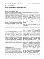
1) WHEN THE RCV LEVER IS IN THE RAISE POSITION
8
9
3
B.D/F
LH
B.U
IN
OUT
RH
T
P
1
3
4
2
2
a2
2B
2A
24MPa
Boom up
Boom down
b2
12
T
Floating
1B
P
1A
Dump
a1
A
B
b1
24MPa
24MPa
Steering system
Roll back
1st pump
2nd pump
21MPa
P
4
F2
11
F1
10 P1
3MPa
CF
U
EF
P2
T
P
Brake system
B
Return line
A
1
23
18
22
19
20
21
When the RCV lever(3) is pulled back, the boom spool on the second block is moved to raise
position by pilot oil pressure from port 3 of RCV.
The oil from main pump(1) flows into main control valve(2) and then goes to the large chamber of
boom cylinder(9) by pushing the load check valve of the boom spool through center bypass circuit
of the bucket spool.
The oil from the small chamber of boom cylinder(9) returns to hydraulic oil tank(19) through the
boom spool at the same time.
When this happens, the boom goes up.
6-4
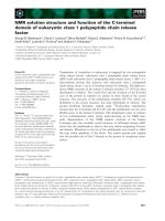
2) WHEN THE RCV LEVER IS IN THE LOWER POSITION
8
9
3
B.D/F
LH
B.U
IN
OUT
RH
T
P
1
3
4
2
2
a2
Check valve
2B
2A
24MPa
Boom up
Boom down
b2
12
T
Floating
1B
P
1A
Dump
a1
A
B
b1
24MPa
24MPa
Steering system
F2
11
1st pump
2nd pump
21MPa
P
4
Roll back
F1
10 P1
3MPa
CF
U
EF
P2
T
P
Brake system
B
Return line
A
1
23
18
22
19
20
21
When the RCV lever(3) is pushed forward, the boom spool on the second block is moved to lower
position by pilot pressure from port 1 of RCV.
The oil from main pump(1) flows into main control valve and then goes to small chamber of boom
cylinder(9) by pushing the load check valve of the boom spool through center bypass circuit of the
bucket spool.
The oil returned from large chamber of boom cylinder(9) returns to hydraulic tank(19) through the
boom spool at the same time.
When the lowering speed of boom is faster, the return oil from the large chamber of boom cylinder
combines with the oil from the pump through the check valve, and flows into the small chamber of
the cylinder.
This prevents cylinder cavitation by the negative pressure when the pump flow cannot match the
boom down speed.
6-5
3) WHEN THE RCV LEVER IS IN THE FLOAT POSITION
8
9
3
B.D/F
LH
B.U
IN
OUT
RH
T
P
1
3
4
2
2
a2
2B
2A
24MPa
Boom up
Boom down
b2
12
T
Floating
1B
P
1A
Dump
a1
A
B
F2
11
1st pump
2nd pump
21MPa
P
4
Roll back
b1
24MPa
24MPa
Steering system
F1
10 P1
3MPa
CF
U
EF
P2
T
P
Brake system
B
Return line
A
1
23
18
22
19
20
21
When the RCV lever(3) is pushed further forward from the lower position, the pilot pressure
reaches to 13-15 bar, then the boom spool on the second block is moved to floating position.
The work ports(2A), (2B) and the small chamber and the large chamber are connected to the
return passage, so the boom will be lowered due to it's own weight.
In this condition, when the bucket is in contact with the ground, it can be move up and down in
accordance with the shape of the ground.
6-6
4) WHEN THE RCV LEVER IS IN THE DUMP POSITION
8
9
3
B.D/F
LH
B.U
IN
OUT
RH
T
P
1
3
4
2
2
a2
2B
2A
24MPa
Boom up
Boom down
b2
12
T
Floating
1B
P
1A
Dump
a1
A
B
1st pump
2nd pump
F2
11
21MPa
P
4
Roll back
b1
24MPa
24MPa
Steering system
F1
10 P1
3MPa
CF
U
EF
P2
T
P
Brake system
B
Return line
A
1
23
18
22
19
20
21
If the RCV lever(3) is pushed right, the bucket spool on the first block is moved to dump position by
pilot oil pressure from port 2 of RCV.
The oil from main pump(1) flows into main control valve(2) and then goes to the small chamber of
bucket cylinder(8) by pushing the load check valve of the bucket spool.
The oil at the large chamber of bucket cylinder(8) returns to hydraulic tank(19) through the bucket
spool.
When this happens, the bucket is dumped.
When the dumping speed of bucket is faster, the oil returned from the large chamber of bucket
cylinder combines with the oil from the pump, and flows into the small chamber of the cylinder.
This prevents cylinder cavitation by the negative pressure when the pump flow cannot match the
bucket dump speed.
6-7
5) WHEN THE RCV LEVER IS IN THE ROLL BACK(Retract) POSITION
8
9
3
B.D/F
LH
B.U
IN
OUT
RH
T
P
1
3
4
2
2
a2
2B
2A
24MPa
Boom up
Boom down
b2
12
T
Floating
1B
P
1A
Dump
a1
A
B
b1
24MPa
24MPa
Steering system
1st pump
2nd pump
F2
11
21MPa
P
4
Roll back
F1
10 P1
3MPa
CF
U
EF
P2
T
P
Brake system
B
Return line
A
1
23
18
22
19
20
21
If the RCV lever(3) is pulled left, the bucket spool on the first block is moved to roll back position by
pilot oil pressure from port 4 of RCV.
The oil from main pump(1) flows into main control valve(2) and then goes to the large chamber of
bucket cylinder by pushing the load check valve of the bucket spool.
The oil at the chamber of bucket cylinder(8) returns to hydraulic tank(19) through the bucket spool.
When this happens, the bucket roll back.
When the rolling speed of bucket is faster, the return oil from the small chamber of bucket cylinder
combines with the oil from the pump, and flows into the large chamber of the cylinder.
This prevents cylinder cavitation by the negative pressure when the pump flow cannot match the
bucket rolling speed.
6-8
6) WHEN THE RCV LEVER IS IN THE HOLD POSITION
8
9
3
B.D/F
LH
B.U
IN
OUT
RH
T
P
1
3
4
2
2
a2
2B
2A
24MPa
Boom up
Boom down
b2
12
T
Floating
1B
P
1A
Dump
a1
A
B
b1
24MPa
24MPa
Steering system
1st pump
2nd pump
F2
11
21MPa
P
4
Roll back
F1
10 P1
3MPa
CF
U
EF
P2
T
P
Brake system
C
Return line
B
A
1
23
18
22
19
20
21
The oil from main pump(1) flows into main control valve(2).
In this time, the bucket spool and the boom spool are in neutral position, then the oil supplied to
main control valve(2) returns into hydraulic tank(19) through center bypass circuit of each spool.
In this condition, each cylinder keeps the neutral position, so the boom and the bucket is holded.
6-9
3. MAIN PUMP OPERATION
1) STRUCTURE
10
5
6
7
8
7
6
12
17
5
9
4
3
4
19
5
12
6
7
16
1
14
7
2
6
18
5
15
12
11
13
1
2
3
4
5
6
7
Shaft seal
Circlip
Flange
O-ring
Seal
Seal
Balance plate
8
9
10
11
12
13
14
Driven gear
Drive gear
Front body
Splined coupling
O-ring
Center body
Driven gear
6-10
15
16
17
18
19
20
Drive shaft
Cover
O-ring
Stud assy
Serrated washer
Nut
20
2) OPERATION
18
19,20
3
4
5,6,7
8
10
9
5,6,7
11
15
14
13
16
The main hydraulic pump is a fixed displacement gear type pump. The pump is drive at engine
speed by the transmission. The pump shafts are supported by balance plates(7), flange(3), front
body(10), center body(13) and cover(16).
As the drive gear(9) and (15) turns the driven gears(8, 14), the gear teeth come out of mesh. Oil
flows from the hydraulic tank through the inlet into the cavity between the gear teeth. As the gears
continue to rotate, the oil becomes trapped between the gear teeth and the balance plates(7).
The trapped oil is then carried to the pump outlet. Oil is forced out the outlet to supply the hydraulic
function. As the gears re-mesh, they form a seal to prevent oil from flowing between the gears and
back to the inlet.
The pump uses outlet pressure oil to load the balance plates(7) against the gear faces. This
controls internal leakage to maintain pump displacement.
Outlet pressure fills the area bounded by the seals(5, 6) to force the pressure plate against the high
pressure area or the gear faces. Pump shaft lubrication is achieved by routing outlet pressure oil
into the area between the gear shafts and the balance plates. The oil is collected at the end of the
shafts in the hollow areas in the port and flange plates and routed back to return.
6-11
4. REMOTE CONTROL VALVE
1) STRUCTURE
B
17
4
29
1
24
28
13
2
3
4
6
23
7
1
1
5
26
21
12
3
27
A
15
16
1
4
9
10
3
2
8
25
14
18
15
19
30
11
20
22
A
B
1
3
4
5
6
7
8
9
10
11
Spring pack
Spring
Plunger assy
Plunger assy
Plunger assy
Plunger assy
Body kit
Prefeel kit
Prefeel kit
Detent kit
12
13
14
15
16
17
18
19
20
21
Prefeel cage assy
Spindle retainer
Spindle
Nut
Lever assy
Handle assy
Lever assy
Socket screw
Connector assy
Rubber boot
6-12
22
23
24
25
26
27
28
29
30
Hand coil
O-ring
Wiper seal
Plug
Boot retainer collar
Handle adapter
Nut
Nut
Insulation tube
2) HYDRAULIC OPERATION
1
26
25
24
2
3
4
23
22
21
5
20
6
19
18
7
17
8
16
15
9
14
10
11
12
B.D/F
B.U
IN
OUT
Port
T
P
1
3
4
2
Hydraulic circuit
1
2
3
4
5
6
7
8
9
Piston attachment
Armature plate
Prefeel spindle
Hold coil
Retaining plate
Prefeel cage assembly
Spring chamber
Body kit
Pressure chamber
10
11
12
13
14
15
16
17
18
13
Port name
Port size
1
Boom down
1/4 BSPP
2
Bucket dump
1/4 BSPP
3
Boom raise
1/4 BSPP
4
Bucket crowd
1/4 BSPP
P
Supply pressure
1/4 BSPP
T
Tank
1/4 BSPP
Pressure reducing v/v housing
Service port
Inlet adapter
Inlet port
Pressure reducing v/v piston
Return spring
Spring pack subassembly
Characteristic spring
Spindle guide subassembly
6-13
19
20
21
22
23
24
25
26
Spindle subassembly
Spindle guide retainer
Mounting plate
Boot retaining plate
Guide
Spindle
Universal joint
Lever housing
(1) Neutral position
2
1
The spring pack subassembly contains the pressure reducing piston(1) which has a center hole
machined from the service port end. This center hole links with a cross hole which in the normal
condition, that is with the lever not selected, connects the service port to the spring chamber(2). This
spring chamber(2) is in turn connected to tank and as such the pilot can on the MCV, to which this valve
is connected, would be connected to tank and the MCV spool would therefore be in the neutral position.
6-14
(2) Metering position
1
2
3
4
The lever housing is selected and this in turn operates the spindle(1) which in turn depresses the
operating spindle. This operating spindle now compresses the return spring(2) and starts to select the
characteristic spring. As there is currently no resistance, the pressure reducing valve piston(3) moves
further down in its bore. As this pressure reducing piston moves lower in its bore this service port
connection to tank, through the cross holes, is initially cut off as the cross hole pass under the land. As
the pressure reducing piston moves further then the cross holes open into the pressure chamber(4),
which is connected to the 30 bar supply, and so at that point the 30 bar supply is connected to the
service port. This also connects to the pilot end cap on the MCV and so spool movement in the MCV
occurs.
6-15
(3) End of metering
1
As the pressure builds up in the RCV service port and MCV pilot can, this same pressure acts on the
end of the pressure reducing valve piston(1), which was initially moved by a force applied to the top of
the characteristic spring. As this pressure increases it starts to react to the force in the characteristic
spring. The piston begins to move back in its bore, and at some point a force balance will occur. When
this happens, and the hydraulic force on the service port end of the piston just starts to exceed the
spring force on the opposite end then the pressure reducing piston moves back in its bore until the cross
hole moves back under the land and so the 30 bar supply to the port is cut off.
6-16
(4) Fully selected
1
2
If the operating lever is now selected further then the force balance on the pressure reducing valve
piston(1) is upset and supply pressure is once again connected to the service port, until a force balance
is restored.
Similarly, if the operating lever is moved back towards neutral then the force balance is once again
upset, this time in the opposite direction and the service port hydraulic force now being greater than the
characteristic spring force, the pressure reducing valve piston moves such that the cross holes open
into the spring chamber(2) and some pressure is lost until the balance is once again restored when the
cross hole moves back under the land.
In this way pressure supplied to the MCV pilot can, and so spool movement, is proportional to the lever
movement of the RCV.
There is a point in the stroke of some of the RCV assemblies where progressive movement of the MCV
spool is no longer necessary due to the spool position and flow/pressure characteristics and the
pressure reducing valve piston is mechanically forced into a position where the cross holes are
constantly held open to the pressure chamber. This happens when the pin fitted to the operating
spindle contacts the top of the pressure reducing valve piston and this mechanical force overrides any
hydraulic balancing forces.
The ports controlling boom up and down and bucket roll back are also fitted with a magnetic detents
and/or prefeel ramps.
The port controlling the power down function also controls the boom float function. A prefeel ramp is
fitted at the point on the pilot valve stroke which controls the spool on the MCV to its power lower
position. Moving the lever beyond this prefeel ramp position and to the end of its stroke gives an output
pressure from the RCV which drives the spool in the MCV into a float position. Details on prefeel ramps
can be seen in the next page.
6-17
3) MECHANICAL OPERATION
(1) The Bucket roll back and boom up and
down functions are fitted with a magnetic
detent.
To prevent accidental engagement of this
magnetic detent each of these detent has
a prefeel position just before the armature
plate engages with the hold coil. The right
figure shows the major components in this
assembly.
Armature plate
Hold coil(Magnet)
Prefeel spindle
Prefeel spring
Prefeel ball
Prefeel cage assy
(2) As the lever is operated the prefeel
spindle and armature plate are depressed
in the bore and towards the end of the
stroke, the prefeel ball, loaded by the
prefeel spring, contacts the ramp on the
prefeel spindle. This provides a physical
restriction to further lever movement as a
step increase in force is required to
overcome the preload of the prefeel
mechanism.
At this point there is still a gap between
the armature plate and the hold coil,
therefore the valve can be operated
without accidentally engaging magnetic
detent.
(3) If an extra amount of force is applied to
the operating lever the force of the prefeel
mechanism can be overcome and
magnetic detent engaged. This allows
the function to remain fully selected
without further operator demand. The
lever automatically returns to neutral
when the electric current is switched off
due to the position of the loader reaching
proximity sensors. Manual override from
magnetic detent is always possible.
6-18
5. MAIN CONTROL VALVE
1) STRUCTURE(1/2)
62
2, 3
61
63
4
5
59
60
58
22
39
T
2A
1
1A
2B
P
1B
38
24
62
61
6
73
7
72
4
5
71
69
72
41
42
24
43
70
25
68
21
73
40
24
71
23
74
25
75
76
26
77
70
68
1
2
3
4
5
6
7
21
22
23
24
25
Inlet housing
O-ring
O-ring
Plug
O-ring
Plug
O-ring
Spool
Spool section
Cover
O-ring
Lock washer
26
38
39
40
41
42
43
58
59
60
61
62
Bolt
Spool
Spool section
Seal extension
O-ring
Sleeve
Cover
Outlet housing
Plug
O-ring
Hexagon nut
Washer
6-19
63
65
68
69
70
71
72
73
74
75
76
77
Tie stud
Stop
Housing
Check valve
O-ring
Back up ring
O-ring
Spring
Check valve
Poppet
Spring
Adjusting screw
65
2) STRUCTURE(2/2)
64
25
54
66
52
48
50
55
36
25
44
56
47
49
35
28
44
46
31
20
53
33
19
37
34
30
16
27
24
29
14
28
37
10
27
17
18
68
70
57
51
32
15
45
24
13
77
11
76
12
75
74
89
2B
P
71
T
2A
1A
1B
72
73
81
80
78
79
8
9
10
11
12
13
14
15
16
17
18
19
20
24
O-ring
Back up ring
Pin
Plunger
Sleeve
Spring
O-ring
Pilot housing
O-ring
Spring
Poppet
Adjusting screw
Lock nut
O-ring
25
27
28
29
30
31
32
33
34
35
36
37
44
45
46
47
48
49
50
51
52
53
54
55
56
57
64
66
Lock washer
Seal retainer
O-ring
Adapter
Spring retainer
Spring retainer
Screw
Spring
Shim
Cover
Bolt
Shim
Seal retainer
Circlip
6-20
Spring retainer
Spring retainer
Shim
Shim
Spring retainer
Spring
Spring
Spool cap
Cover
Screw
Washer
O-ring
Screw
Stop
68
70
71
72
73
74
75
76
77
78
79
80
81
Housing
O-ring
Back up ring
O-ring
Spring
Check valve
Poppet
Spring
Adjusting screw
O-ring
Cap
Spring
Check valve
STRUCTURE
b2
T
a2
a1
2A
2B
1A
1B
b1
P
T
a2
2B
24Mpa
2A
Boom up
Boom down
b2
Floating
1B
1A
Roll back
b1
24Mpa
24Mpa
a1
Dump
21Mpa
P
Port
Port name
Port size
P
From main pump
1 1/16UNF
T
To hydraulic tank
1 5/16UNF
1A, 1B
To bucket cylinder port
1 1/16UNF
2A, 2B
To boom cylinder port
1 1/16UNF
a1, b1
Bucket pilot port
7/16UNF
a2, b2
Boom pilot port
7/16UNF
6-21
2) BOOM SECTION OPERATION
(1) Spool in neutral
NEUTRAL
T
a2
2B
24Mpa
2A
BOOM UP
BOOM DOWN
b2
FLOATING
1B
1A
ROLL BACK
b1
24Mpa
a1
24Mpa
DUMP
2B
2A
Low pressure passage
If the remote control valve is not operated, the oil supplied from the pump port passes through the
neutral passage to the low pressure passage at the outlet section, and then returns to the tank port.
6-22
(2) Boom raise position
T
a2
2B
24Mpa
2A
BOOM UP
BOOM DOWN
b2
FLOATING
1B
1A
ROLL BACK
b1
24Mpa
a1
24Mpa
DUMP
2A
2B
a2
Load check valve(1)
When the pilot pressure from remote control valve is supplied to the pilot port(a2), the spool moves to
the right and the neutral passage is closed.
The oil supplied from the pump pushes up the load check valve(1) and flow into boom cylinder port(2A).
The pump pressure reaches proportionally the load of cylinder and fine control finished by shut off of the
neutral passage.
The return oil from cylinder port(2B) flows into the tank via the low pressure passage.
6-23
(3) Boom lower position
T
a2
Check valve(2)
2B
24Mpa
2A
BOOM UP
BOOM DOWN
b2
FLOATING
1B
1A
ROLL BACK
b1
24Mpa
a1
24Mpa
DUMP
2B
2A
b2
Check valve(2)
Load check valve(1)
When the pilot pressure from remote control valve is supplied to the pilot port(b2), the spool moves to
the left and the neutral passage is closed.
The oil supplied from the pump pushes up the load check valve(1) and flow into boom cylinder port(2B).
The pump pressure reaches proportionally the load of cylinder and fine control finished by shut off of the
neutral passage.
The return oil from cylinder port(2A) flows into the tank via the low pressure passage.
When the lowering speed of boom is faster, the return oil from the large chamber of boom cylinder
combines with the oil from the pump through the check valve(2), and flows into the small chamber of
cylinder. This prevents cylinder cavitation by the negative pressure when the pump flow cannot match
the boom lowering speed.
6-24
(4) Boom float position
T
a2
2B
24Mpa
2A
BOOM BOOM
DOWN
UP
FLOATING
b2
1B
1A
ROLL BACK
b1
24Mpa
a1
24Mpa
DUMP
2B
2A
b2
If the remote control lever pushes further more, the pilot pressure from remote control valve rises over
13-15bar and then the boom lowering spool is pushed to the boom floating position, opening up the
neutral passage to tank and simultaneously(2A), (2B) T.
In float position the boom drops quickly due to its own weight.
When the bucket touches the ground and the wheeled loader is moving, the bucket raised or lowered
following the unevenness of the ground due to the (2A), (2B) T connecting.
6-25