RESEACH AND APPLY BIOGAS DIESEL FOR ENGINES ASSEMBLING ON ROAD MOTORIZED MEANS FOR RURAL TRANFIC IN VIETNAM
Bạn đang xem bản rút gọn của tài liệu. Xem và tải ngay bản đầy đủ của tài liệu tại đây (1.89 MB, 27 trang )
MINISTRY OF EDUCATION AND TRAINING
THE UNIVERSITY OF DANANG
NGUYEN VAN ANH
RESEACH AND APPLY BIOGAS - DIESEL
FOR ENGINES ASSEMBLING ON ROAD
MOTORIZED MEANS FOR RURAL
TRANFIC IN VIETNAM
Specialty: Heat Engine Technology
Code: 62.52.34.01
ABSTRACT OF TECHNICAL THESIS
DANANG-2016
The work has finished at
THE UNIVERSITY OF DANANG
The first scientific advisor: Prof.Dr.Sc. Bui Van Ga
The second scientific advisor: Assoc.Prof.Dr. Duong Viet Dung
The first reviewer: Assoc.Prof.Dr. Le Anh Tuan
The second reviewer: Prof.Dr. Vu Duc Lap
The third reviewer: Dr. Le Van Tuy
The thesis is going to be defended at the Council for defended PhD
thesis Technical meeting at the university of DaNang on 29/10/2016
This thesis can be lookup at the university of DaNang:
-
The Learning Resource and Infomation Centre
The Learning Resource Centre
PUBLISHED WORKS OF AUTHOR
[1]
[2]
[3]
[4]
[5]
[6]
[7]
[8]
[9]
[10]
Bui Van Ga, Le Minh Tien, Nguyen Van Dong, Nguyen Van Anh:
“Biogas supplying system for biogas/diesel dual-fuel”. Journal of
science and technology, University of Danang, No 2(25).2008, pp.
17-22.
Bui Van Ga, Nguyen Van Dong, Nguyen Van Anh, Nguyen The
Anh, Ho Tan Quyen: “Motorcycle fueled by compressed Biogas”.
The Nationwide Conference on Pneumatic Mechanical, Danang
City, Vietnam, 22-25/7/2009, pp. 147-156.
Bui Van Ga, Nguyen Van Dong, Nguyen Van Anh, Truong Le
Bich Tram: “Study of the system supplying pressed biogas for
motorbikes ”. The Transport journal, Vietnam, No 12/2009, pp. 7982, 2009.
Bui Van Ga, Phan Minh Duc, Nguyen Van Anh: “Effects of
different parameters on ignition process of biogas-air mixture by a
diesel pilot flame”. The Nationwide Conference on Pneumatic
Mechanical, Nghean, Vietnam, 21-23/7/2011, pp. 117-124.
Tran Thanh Hai Tung, Bui Van Ga, Nguyen Van Anh, Vo Anh
Vu: “Study of effect of compression ratio and biogas composition
to combustion process in internal combustion engine”. The
Nationwide Conference on Pneumatic Mechanical, Nhatrang City,
Vietnam, 26-28/7/2012, pp. 747-756.
Bui Van Ga, Le Minh Tien, Nguyen Van Anh, Vo Anh Vu:
“Simulation of combustion of a biogas-diesel dual fuel engine”. The
Nationwide Conference on Pneumatic Mechanical, Ninhthuan,
Vietnam, 26-28/7/2014, pp. 164-173.
Bui Van Ga, Nguyen Viet Hai, Nguyen Van Anh, Vo Anh Vu, Bui
Van Hung: “In cylinder pressure analysis in biogas-diesel dual fuel
engine by simulation and experiment”. Journal of science and
technology, University of Danang, No 1(86).2015, pp. 24-29.
Bui Van Ga, Nguyen Viet Hai, Nguyen Van Anh, Bui Van Hung:
“Biogas-Diesel hybrid engine”. Journal of science and technology,
University of Danang, No 03(88).2015, pp. 26-29.
Bui Van Ga, Nguyen Van Anh, Nguyen Viet Hai, Vo Anh Vu, Bui
Van Hung: “An equivalence ratio ϕ measurement method for
biogas diesel dual fuel enginel”. Journal of science and technology,
University of Danang, No 05(90).2015, pp. 43-46.
Bui Van Ga, Bui Thi Minh Tu, Nguyen Viet Hai, Nguyen Van
Anh: “Simulation of Combustion and CO Emission of BiogasDiesel Dual Fuel Engine ”. The Transport journal, Vietnam, No
4/2016, pp. 67-70, 2016.
1
INTRODUCTION
WHY CHOOSE TOPICS: In Vietnam, the demand for agricultural
machinery and motivation increases from 20-25% yearly, together
with the agricultural production of 84,5 million tonnes of emissions
from crop waste, 82.5 million tonnes livestock, 65.1 million tonnes of
CO2 equivalent, accounting for 43.1% of total greenhouse gas
emissions of the country [71]. Forecast emissions from agricultural
activities in 2030 will continue to rise to nearly 30% [70]. According
to forecasts the remaining time can be exploited for oil and natural gas
in our country after 2030 [5]. Besides, every year we can produce 4
billion m3 of biogas.
For this reason, the theme "Reseach and apply biogas diesel for engines assembling on road motorized means for rural
tranfic in Vietnam" is urgently needed, and contribute to reducing
environmental pollution, just search are clean alternative fuels,
contributing to diversify fuel sources for heat engines and bring
economic benefits contribute to improving the lives of people.
RESEARCH OBJECTIVES: The thesis would solve two main
purposes: Research amnesty equivalent to ϕ coefficient optimized to
work with the various modes and biogas composition ratio CH4
change. Designing integrated speed controller mounted on tractor
operation K2600 multi mode dual fuel use biogas-diesel. The thesis
also aims to contribute to improving application technologies biogas
fuel on motor vehicles popular in rural Vietnam.
SUBJECTS AND SCOPE OF THE STUDY
Research subjects: In this thesis, the author choose EV2600NB Vikyno engine mounted on tractor diesel K2600 that switches to
dual fuel diesel-powered biogas as the object of study.
2
Research scopes:
-Research and experimental determination of the optimal
equivalent ϕ EV2600-NB engine dual fuel applications biogas-diesel.
-Research renovated motor speed regulator EV2600-NB dual
fuel applications biogas-diesel.
-Research on the process of creating a dual fuel engine
combination of biogas-diesel.
RESEARCH METHOD: The thesis use research methods and
theoretical modeling combined with empirical research.
MEANING OF SCIENCE AND PRACTICE OF THEMES
Scientific Significance: The thesis contributes basic research
and in-depth applications dual fuel biogas engine biogas-diesel in
Vietnam.
Practical significance: Our country has more than 70.4%
(2009) of the population lives in rural areas. Organic waste from the
agricultural production process is suitable for the production of biogas,
matching the energy consumption devices with small capacity,
including small combustion engine powered by biogas to serve for
production and rural life have a huge demand. The theme has great
significance in addressing the current energy problems and reduce
environmental
pollution, placing on the
market
means
of
transportation clean, new.
Chapter 1: OVERVIEW OF RESEARCH
1.1. Characteristics of rural transportation in Vietnam
1.2. Overview of economic development in rural farm Vietnam
As of 2011, there were 8642 crop farms, accounting for 43%
of total farm; 6.202 farms, accounting for 30.9%; 4.443 aquaculture
3
farm seafood, accounting for 22.1%; 737 collective farms, accounts
for 3.7% and 51 forest farms, accounting for 0.3% [77].
1.3. The use of motorized vehicles in rural Vietnam
1.3.1. Demand engines served for motor vehicles in rural Vietnam
According to the average estimate, the demand for agricultural
machinery and motivation from 20-25% annual increase, use of
machinery in agriculture is growing in number and diversity of the
standard categories.
1.3.2. These kinds of motorized transport in rural Vietnam
1.4. Biogas reserve in Vietnam
1.4.1. Oil and natural gas reserve
1.4.2. Fertility biogas from organic waste and agricultural residues
According to calculations in 2011, agricultural production
84.5 million tons emissions from crop waste, 82.5 million tonnes of
waste from livestock, 65.1 million tonnes of CO2 equivalent,
accounting for 43.1% total greenhouse gas emissions of the country
[71]. Forecast emissions from agricultural activities in 2030 will
continue to rise to nearly 30% [70].
1.4.3. Biogas reserve in rural Vietnam
If averaging 200m3 biogas/ton and 10% biomass raw material
is converted into biogas above, each year we can produce 2 billion m3
of biogas. Plus 2 billion m3 of biogas produced from livestock waste,
each year we can produce 4 billion m3 of biogas [5].
1.5. The domestic and international research on the use of biogas
in engines
1.5.1. Findings in the world on the use of biogas in engines
1.5.2. Research results in the country on the use of biogas in engines
1.6. Conclusions
4
From research on this review we see demand for the motor
service motor vehicles in rural Vietnam and other countries around the
world grow very large annual follow, accompanied by the emission of
gases causing the greenhouse effect, the major cause of climate
change, sea level rise, threatening the life of humanity on the planet.
Project "Reseach and apply biogas-diesel for engines
assembling on road motorized means for rural tranfic in Vietnam
" will contribute part of the process of resolving the issue thoroughly.
Chapter 2: FUNDAMENTAL THEORY FOR BIOGAS DUAL
FUEL BIOGAS-DIESEL ENGINES
2.1. Standard biogas as a fuel for internal combustion engines
2.1.1. The basic nature of biogas as a fuel for internal combustion
engines
2.1.2. Proposed Standard biogas as fuel for internal combustion
engines in Vietnam
From result calculation criteria above fuel biogas combined
with empirical research on biogas production from different raw
materials, we propose a simple set of standards when using biogas as
fuel for action combustion engine (table 2.1) [5].
Table 2.1: Proposed Standard biogas to fuel internal combustion engines
Criteria
Prescribed limits
Unit
Low Wobbe index
21,69-32,04
MJ/nm3
Index methane
111-121
-
H2S
< 1000
ppmV
2.2. Theoretical foundations of mixed offer dual fuel biogas-diesel
engine
2.2.1. Affect the uniformity of the mixture to combustion
5
2.2.2. Theory combustion mixture before mixing locally
2.3. Design of the engine speed EV2600-NB biogas dual fuel dieselbiogas
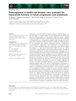
2.3.1. The control principle of dual fuel biogas-diesel engine
The principle of dual fuel engine control biogas-diesel was
introduced in [21]. Dual fuel biogas engine-diesel can convert dieselbiogas fuel during operation, does not require any technical
intervention (figure 2.7).
Springs diesel
Diesel governor
Limit screw 10%
rated injection
Injection Pump
n
Biogas governor
Springs biogas
Biogas butterfly
valve
Limit screw =1.1
Figure 2.7: Control schema of hybrid biogas-diesel engine
2.1.2. Technology converts diesel into
biogas engines-diesel
Step 1: Restoration dynamic balancing
shaft. This step is shown in figure 2.9.
Step 2: Reprocessing gear size 4 figure
Figure 2.9:
2.10b.
a)
b)
Figure 2.10:
6
Step 3: Select and insert the speed
governor biogas: figure 2.11.
Step 4: Renovations lid: figure
2.12.
Figure 2.11:
Step 5: Installation of the system as
drivers: Include more, springs and
tension control mechanism springs. The
size of the structural parts shown on the
detailed drawings figure 2.13.
Figure 2.12:
2.1.3. Operating biogas engine-
Figure 2.13:
diesel dual fuel after conversion
2.4. Calculate the biogas speed regulator
2.4.1. Diagram of calculations and selected parameters
When joints are sliding
displacements Δx section [m],
the results splashed m [kg]
orbiting the center at an angle
Δα
[rad]
and
the
spring
deformation Δy section [m]. l1,
l2 and l3 [m]: the size of the
Figure 2.14:
7
more controlled speed controller. l4 [m]: length as throttle control
(figure 2.14).
2.4.2. The step count
2.4.2.1. Count to recover Fhp
2.4.2.2. Count to maintain Fdt
2.4.2.3. Character balance of sliding joints
2.5. Conclusions
The study results above, we get the following conclusions:
- Standard of biogas as a fuel for internal combustion engines and
standard proposed biogas as a fuel for internal combustion engines in
Vietnam.
- The principle of dual fuel biogas engine-diesel presented in this work
can be applied on most types of diesel-powered switching to biogas.
- Process improvement technology conversion and installation of a
complete compact speed controller for motor applications EV2600NB dual fuel biogas-diesel.
- Mapping and calculate the parameters of the dynamic speed
regulation biogas.
Chapter 3: PROCESS SIMULATION AND BURNING
MIXTURES OF BIOGAS ENGINE-DIESEL DUAL FUEL
3.1. Theoretical basis of determination of equivalence ϕ
If you see only biogas containing CH4 and CO2 two
components, the equivalent ratio φ is determined according to the
following expression:
1600x.Qbio
23Q air 4 x 11.(100 x)
(3.1)
Where: Qbio is the biogas flow (kg/h); Qair is the air flow (kg/h);
x is the component in biogas CH4 by volume.
8
3.2. Simulating the process of creating mixed-motive diesel dual
fuel biogas
3.2.1. Features texture generator biogas-air mixture
3.2.2. Calculating the size of the
basic mixtures
According to [22], we
computed the basic geometrical
parameters of the mixtures as
Figure 3.5:
figure 3.5.
3.2.3. Simulation mixtures of Ansys® fluent software
3.2.3.1. Building a model in Ansys® fluent mixture
To compare the homogeneity of the mixture to the intake system
configurations ranging simulation is done in 6 cases (figure 3.6).
3.2.3.2. Simulation model homogeneity of the mixture Ansys® fluent
To
compare
the
homogeneity of the mixture to
the intake system configurations
ranging simulation is done in 6
cases. The biogas emergency
a)
b)
c)
cases through the narrow slit of
2mm, including: (1) no mixtures
chamber (figure 3.7a), (2) has a
cylindrical
(figure
cylinder
mixing
3.7b),
(3)
chamber
chamber
mixing
Φ8mm
d)
e)
f)
Figure 3.7: Configuration of the system
load using simulation
perforated membrane (figure 3.7c), (4) a cylindrical mixing chamber
with perforated membrane Φ4 (figure 3.7d). The case provides Φ6
9
biogas through 8 holes include: (1) mixing spherical chamber (figure
3.7e), (2) a cylindrical mixing chamber (figure 3.7f)
3.2.3.3. Meshing
3.2.3.4. Set boundary conditions
Table 3.3: Results calculated excess pressure medium pace
engine output at the location of the venturi mixing
n [v/ph]
1000
1200
1400
1600
1800
2000
2200
pmix [Pa]
-1158
-1668
-2270
-2965
-3753
-4633
-5606
Conditions edge selected include residual air pressure p_air =
0 [Pa]; The pressure of biogas residues p_bio=50 [Pa]; Excess pressure
of mixed p_mix [Pa] in table 3.3.
3.2.3.5. Simulation dual fuel combustion by Ansys® fluent software
3.3. Simulation results mixed dual fuel biogas-diesel engine
3.3.1. The simulation results of mixtures
3.3.2. The simulation results of homogeneity of mixtures
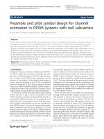
Figure
3.15
shows
the
result calculate the
CH4 concentration
and fluid speed
after more uniform
membrane (figure
3.16)
on
longitudinal
a)
b)
c)
d)
Figureof3.16:
Figure 3.15: Distribution
CH4 concentration in
the intake system when no mixing chamber (a), has
a cylindrical mixing chamber (b), the mixing
chamber with perforated membrane (c) and the
mixing chamber sphere (d)
symmetry of the
system loaded with different configurations, but the uniformity of CH4
output charging system did not improve much. Based on the
concentration of CH4 and O2 concentrations in the intake system output
10
we can calculate the equivalent ratio of the mixture ϕ with the given
boundary conditions.
Figure 3.17a, b
presents
1.6
1.4
1.3
equivalent
1.4
coefficient equivalent of
1.2
1
variation in the y and z on
1.2
Series1
Series2
Series3
Series4
Series5
Series6
Series1
Series2
Series3
Series4
Series5
Series6
1.1
1
0.9
0.8
0.8
cross drainage from the
0.7
1.6
mouth
of
1.6
0.6
-30
1.4
the
-20
-10
0.6
0
10
1.4
intake
Series1
Không buồng hòa trộn, khe 2mm
Series2
Buồng hòa trộn trụ, khe 2mm
1.2 khe
Series3
Buồng hòa trộn trụ và lưới lỗ 8,
Series4
Buồng hòa trộn trụ và lưới lỗ 4, khe
Series5
Buồng hòa trộn cầu, khe 2mm
1
Series6
Buồng hòa trộn trụ, 8 lỗ 6
1.2
manifold 5 mm. We see no
1
case manifold or manifold
a)
0.6
chamber
-30
-20
cylindrical
-10
with
0
10
20
-30
30
mixing
chamber with perforated
inner
membrane,
the
of
-20
-10
0
Độ mở bướm ga
Series1
10
Series2
20
Series3
30
40
Series4
50
Series5
60
Series6
0.94
0.9
2mm
2mm
-20
-10
0.86
0.82
3.19a
0
10
20
30
1.02
1.02
0.98
1
0.94
0.98
Series1
Series2
1.02
Series3
0.98
Series4
0.94
Series5
Series6
0.9
0.82
0.96
0.94
Độ mở bướm ga
Series1
10
Series2
20
Series3
30
40
Series4
50
Series5
60
Series6
0.92
0.9
0.78
0.86
0.74
-30
-20
-10
0.88
0.82
0.78
0
10
0.7
-20
-10
0
varying performances of
30
z(mm)
b)
0.6
0.7
0.74
-30
20
Figure 3.17:
0.78
Figure
10
Series1
Không buồng hòa trộn, khe 2mm
Series2
Buồng hòa trộn trụ, khe 2mm
Series3
Buồng hòa trộn trụ và lưới lỗ 8, khe 2mm
Series4
Buồng hòa trộn trụ và lưới lỗ 4, khe 2mm
Series5
Buồng hòa trộn cầu, khe 2mm
Series6
Buồng hòa trộn trụ, 8 lỗ 6
0.86
variation
coefficient equal huge.
-30
0.9
1.02
0.98
degree
y(mm)
30
0.8
0.8
mixing
20
10
20
20
30 -30
y(mm)
30
the lead / max theo y
0.86
-20
0.74
-10
0
10
20
30
z(mm)
0.7
-30
-20
-10
0
a)
10
20
30
b)
Figure 3.19:
and z when the throttle
open from 10 to 60 than fully closed position. This result shows that
the larger the throttle valve opening degree of uniformity in the y
increase. However, the fluctuation of under the z, in contrast, larger
throttle valve opening level of higher oscillation (figure 3.19b).
3.3. Influence of operational factors to feature dual fuel biogasdiesel engine
3.3.1. The relationship between the mixture ratio and the coefficient
ϕ equivalent of biogas-diesel engine
Series1
Series2
Series3
Series4
Series5
Series6
11
In calculating combustion ratio to define mixture f (mixture
fraction) by the expression:
f
r
(3.8)
Where: r is the amount of air necessary for complete
combustion per unit volume of fuel.
Table 3.7: Value f and ϕ with biogas M6C4; M8C2 and 10% diesel
0.03
0.05
0.07
0.09
0.11
0.13
0.15
0.17
M6C4
0.198958
0.338578
0.484203
0.636229
0.795088
0.96125
1.135232
1.317599
M8C2
0.326495
0.555615
0.794589
1.044068
1.304759
1.577436
1.862945
2.162213
f
ϕ
3.3.2. Evaluation process burning biogas-diesel fuel
()
Priming jet diesel (T0)(a)
352
355
358
362
365
370
375
385
Figure 3.22:
Spark (%CH4)(b)
12
Figure 3.22 compares the burning process is started by
priming jet diesel (figure 3.22a) and combustion is started by sparks
(figure 3.22b). We see in the case ignited by sparks, flames membrane
form polar caps do demand attention compression ignition. Films fire
spreading from launch point to the farthest regions of the combustion
chamber.
3.3.3. Calculate diesel combustion in the engine Vikyno EV2600
Figure
3.23
varying
25
3
concentrations introduce diesel, oxygen
O2
22
and equivalence ratio ϕ in the engine
2.4
C12H23
ϕ
19
1.8
16
1.2
13
0.6
combustion chamber dual fuel biogasdiesel concentration in the mixture is
very low CH4 1/1000. This case can be
10
0
0
seen as combustion in diesel engines.
60
in
180
240
300
360
φ (độ)
Figure 3.24 referral agent temperature
variation
120
Figure 3.23:
the
90
combustion chamber
2500
80
Nén
70
2000
under
the
crankshaft
engine
rotation
10mg/ct
20mg/ct
50mg/ct
60
40mg/ct
30mg/ct
40mg/ct
30mg/ct
1500
50
20mg/ct
50mg/ct
40
1000
30
20
speed runs at 1600
500
10
0
0
0
rev/min.
We
higher
maximum
temperature
60
120
180
240
300
360
0
60
120
180
240
300
see
Figure 3.24:
Figure 3.25:
cycle
while the larger spray. However, when a larger amount of injection 40
mg/cycle, the dark mixture begins to incomplete combustion leads to
the increase of temperature began to fall. This leads to increased levels
of maximum pressure also decreased (figure 3.25).
360
13
3.3.4. Calculating combustion engine biogas-diesel dual fuel
3.3.4.1. Impact of fuel spray primer
The introduction
of variable figure 3.28a-e
6
diesel,
concentration,
methane
equivalent
and
coefficients
C12H23
fi
3
O2
2.1
12
12
O2
2
1.4
6
6
1
0.7
0
0
0
60
120
180
240
300
0
360
0
0
60
120
180
a)
240
300
25
CH4
2.4
3
20
25
CH4
2.4
C12H23
20
C12H23
fi
fi
O2
O2
1.8
15
1.8
15
1.2
10
1.2
10
0.6
5
0.6
5
0
0
0
injection of 20 mg/cycle.
0
60
120
180
240
300
0
0
360
60
120
180
240
300
Ratio mixture f (mixture
fraction) 0.1; 0.07; 0.05;
0.04; 0.03. The same
amount
injection,
of
the
diesel
mixture
ratio of up to 0.07 f
equivalent ϕ bat the first
c)
d)
3
25
CH4
2.4
20
C12H23
fi
O2
1.8
15
1.2
10
0.6
5
0
0
0
60
120
180
240
300
coefficient greater than 1,
e)
the amount of residual
Figure 3.28:
fuel
in
the
360
b)
3
80% CH4 and diesel
18
fi
2.8
C12H23
ϕ when the engine runs at
with biogas containing
CH4
18
CH4
crankshaft rotation angle
a speed of 1600 rev/min
24
3.5
4
oxygen
4.2
24
5
360
mixture
increases. Variability results in cylinder pressure and the indicator
chart in this case shown in figure 3.29 and 3.30. Peak pressure curve
increases with f. However, when the equivalent ratio of approximately
1, the maximum pressure in the cylinder begins to rise slowly. Figure
3:32 and 3:33 introduces influence formation of the mixture ratio of f
360
14
to pressure variation according to the angle of rotation of the
crankshaft and the graph of the engine when running at full speed by
biogas M8C2 1600 rev/min and diesel injection of 10mg/cycle.
Figure 3.29:
Figure 3.32:
Figure 3.30:
Figure 3.33:
3.3.4.2. Influence of engine speed
Figure 3.36:
Figure 3.37:
15
Figure 3.36 pressure variability introduced crankshaft rotation
angle and shape of the figure 3.37 introducing dual fuel biogas enginediesel when running at 2000 rev/min with diesel injection of biogas
M8C2 and 10mg/cycle. Ratio mixture f varies from 0.03 to 0.1.
3.3.5. Features local road engine dual fuel biogas-diesel
Figure 3.41 introducing the indicator variable cycle engine
powered by biogas dual fuel with diesel priming injection of
10mg/cycle ratio corresponding to the different mixtures. Useful
capacity of the engine is calculated from the cycle indicator, engine
speed and motor performance. In this work, because it does not directly
measure the pressure in the combustion chamber indicator
performance engine motor should be selected: ηm=0,82.
Figure 3.41:
Figure 3.42:
3.4. Conclusions
From research results above, we get the following conclusions:
- The maximum value of the combustion pressure depends on the
equivalence ratio ϕ general of the mixture and achieve maximum value
when ϕ is approximately 1. The maximum pressure in the cylinder
increases slowly over ϕ in the low but increasing Actions in the area
16
of high value ϕ. When working with biogas engines poverty, increase
diesel injection increases the directive. However when the engine
works with rich biogas, diesel injection increase general make too bold
mixture leads to reduced engine indicator. As the speed increases, the
cycle indicator decreased engine.
- In the same conditions of supply of biogas, the diesel injection
quantity increases, the peak pressure curve barely changed but higher
expansion path leading to the indicator rose. When the engine runs on
biogas containing 80% CH4 mixing ratio with f = 0.1 and 10 mg of
diesel spray primer/ct the useful capacity of the engine-diesel dual fuel
biogas equivalent to diesel power.
Chapter 4: RESEARCH AND EXPERIMENTAL RESULTS
4.1. Restoration diesel tractor to tractor K2600 dual fuel biogasdiesel
4.1.1. The technical specifications of tractor K2600
4.1.2. Experiment engine
4.2. Process improvement tractor tractor diesel dual fuel K2600
into biogas-diesel
4.2.1. Arrange installation of biogas systems on tractors rack K2600
4.2.2. Installation of compressed biogas tanks to tractors K2600
4.2.3. Insert the venturi throat supply biogas to the engine manifold
4.2.4. Operating procedures tractor dual fuel biogas-diesel K2600
4.3. Experimental measurements EV2600-NB engine features dual
fuel biogas-diesel
4.3.1. The equipment for experiments
4.3.1.1. Froude dynamometer capacity DPX3
4.3.1.2. Card data recorded NI-6009
4.3.1.3. The sensors record engine operating data
17
4.3.1.4. H2S and CO2 purifiers and gas analyzers Gas
4.3.1.5. Measuring systems connected to PC
4.3.2. Experimental layout
Engine testing system is mounted on light trucks to be mobile
to biogas production [22]. Figure 4.17 diagrams introduce
experimental system consists of five main components: (1) preparation
section biogas fuel composition requirements; (2) part dynamometer:
Froude hydraulic dynamometer
DPX3
and
water
supply
systems; (3) the engine test:
EV2600-NB; (4) the sensor: the
sensor
signal
taken
dynamometer and engine are
connected to the computer
through a modified A/D; (5)
controls:
control
motor,
Figure 4.17: Diagram of experimental setup
dynamometer and read/write test data.
4.4. Laboratory results biogas speed controller
Figure 4.18: Outer curve at a speed thing 1300rpm, 1750 rpm and 2100 rpm
Variable capacity in the engine speed when speed-controlled
elongation springs 35,3mm, 39,5mm, 41,3mm. According to the
18
calculations in table 2.5, with this spring elongation speed regulator
effects in 1200 rpm, 1800 rpm, 2000 rpm. However, the experimental
results showed that the impact speed was clocked at 1300 rpm
respectively, 1750 rpm, 2100 rpm, the greater the theoretical value of
100 rpm, less than the theoretical value 50 rpm (figure 4.18).
4.5. The influence of the intake system and the engine operating
mode to dual fuel equivalent ratio ϕ
4.5.1. The influence of the throttle opening
Equivalent variation coefficient ϕ
1.8
according to the throttle opening with
1.6
biogas containing 60%, 70%, 80% CH4 and
1.2
engine running at 2000 rpm. To achieve
0.8
equivalence ratio ϕ = 1 as biogas containing
80% CH4
1.4
1
60% CH4
70% CH4
0.6
0.4
0.2
60% CH4, the throttle to open 75 to 80%,
0
20
40
60
80
100
% độ mở bướm ga
corresponding to 70% of biogas containing
Figure 4.19:
CH4, and 80% CH4, conditions in order to
achieve with the throttle opening 65% and 55% (figure 4.19).
4.5.2. Influence of engine speed
Coefficient
of
variation
of
equivalent throttle opening degree ϕ
according to the engine speed n = 1800
rpm, n = 2000 rpm and n = 2200 rpm. We
see that when the engine speed decreases,
the equivalent ratio ϕ slightly. When the
throttle opening larger the influence of
engine speed increasing to ϕ (figure 4.20).
4.5.3. Influence of engine power
1.6
1.4
n=1800 v/ph
1.2
1
n=2200 v/ph
0.8
n=2000 v/ph
0.6
0.4
0.2
20
40
60
80
100
% độ mở bướm ga
Figure 4.20:
19
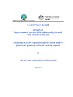
Useful capacity variation coefficient of equivalent ϕ of dual
fuel engine when running on biogas-diesel contains 60% CH4, 70%
CH4 and 80% CH4. Experimental results
Pe(kW)
show that the content of CH4 in biogas
18
80% CH4
16
higher the peak of the epidemic curve as
14
ϕ = 1 position. Can get an approximate
12
70% CH4
10
value of ϕ at which the useful capacity of
60% CH4
8
the engine reaches its maximum value of
6
4
1.15; 1.10 and 1.05 respectively with
0.2
0.4
biogas containing 60% CH4, 70% CH4
0.6
0.8
1
1.2
1.4
1.6
Figure 4.21:
and 80% CH4 (figure 4.21).
4.6. Analysis of the features of the dual fuel engine biogas-diesel
4.6.1. Outer curve of the engine dual fuel biogas-diesel
The experimental results measured characteristic lines outside
of the dual fuel engine after renovation. Diesel injection quantity is
fixed at 10% of maximum injection. Biogas provides engine
component change CH4 at 60%, 70% and 80% (figure 4.22).
Figure 4.23 shows external characteristics of dual fuel engines
run on biogas-diesel to biogas containing 60% CH4, 70% CH4 and 80%
CH4 versus black
20
release
18
18
16
outer curve diesel
Pe (HP)
16
characteristics and
Đường đặc tính nhả
khói đen động cơ
diesel
Pe (kW)
smoke
14
14
12
Đường đặc
tính ngoài
động cơ diesel
12
10
engine. This result
shows
that
the
10
8
8
6
1000
1200
1400
1600
1800
2000
2200
2400
1200
1400
1600
1800
biogas containing
60%
CH4,
the
Figure 4.22:
2000
2200
n (rpm)
n (vòng/phút)
Figure 4.23:
20
maximum power of the engine is smaller than the rated power of the
diesel engine.
4.6.2. Local characteristic lines of dual fuel biogas engine-diesel
20
dual fuel engine when running by biogas
16
containing 80% CH4 compressed by a
factor of ϕ = 0.9 equivalent; ϕ=0.8 and
Pe (HP)
Local characteristic lines of
12
8
ϕ=0.7.
The
similarity
coefficient
4
corresponding to supply biogas valve
1000
1400
1800
2200
n (vòng/phút)
opening at 57%, 52%, 46% (figure
Figure 4.24:
4.24).
4.6.3. Curve speed controller
Experiments
performed
with
20
43,1mm springs stretch, corresponding
2200 rpm. At the start of the experiment,
we adjust the braking load to stabilize the
engine running at a speed of 1000 rpm.
16
Pe (HP)
to a speed controller calculates speed
18
14
12
10
8
1000
1400
1800
2200
n (vòng/phút)
Then gradually reduce brake drag load
and engine speed reached about 2150
Figure 4.25:
rpm, the more drag reduction, decreasing engine power and engine
speed ranges in a narrow range (figure 4.25).
5.2.4. Consumption of diesel fuel to dual fuel engine ignition biogasdiesel
Diesel fuel consumption rate of dual fuel engines run on
biogas containing 70% CH4 when the throttle opening is 60%, 55%
and 50%. Corresponding to the throttle opening 60%, diesel fuel
consumption rate change from 14% (at low speeds) to 16% (at high
21
speeds) than when the engine is run
entirely by diesel. When closing the
throttle to 55%, the change this
percentage from 23% to 34%. When the
throttle opening is 50% diesel fuel
consumption rate of the engine changed
Figure 4.26:
from 30% to 45% (figure 4.26).
4.6.5. Effect of diesel spray
diesel engine's useful dual fuel biogas-
16
Pe (kW)
Effects of spray volume to power
diesel. This result shows that, when the
engine is run with biogas containing 60%
14
Đặc tính ngoài
động cơ diesel
12
10
CH4 is to achieve the rated power of the
diesel engine before renovation we have
to increase to 30% of the diesel injection
8
1200
1400
1600
1800
2000
2200
n (rpm)
Figure 4.27:
spray norms (figure 4.27).
4.7. Conclusions
Research results above we get the following conclusions:
- Process improvement tractor tractor diesel dual fuel K2600 into
biogas-diesel.
- When running on biogas with CH4 concentrations above 70%, motor
fuel biogas-diesel dual just a minimal amount of diesel injection 10%
of the level for ignition spray can ensure outer curve of the higher
hybrid outer curve of the diesel engine. When running on biogas poor
levels of less than 70% CH4, to ensure the rated capacity, the diesel
injection quantity increases with inversely proportional to the
concentration of CH4. When the concentration of CH4 in biogas is
60%, the amount of diesel injection was 30%.
22
- At a given engine speed, engine power decreased rapidly by a factor
equivalent of the mixture. The power of the engine with equivalent
coefficient of ϕ = 0.9; ϕ = 0.8 and ϕ =0.7 respectively, 18HP, 15HP
and 10HP compared 19HP to when the engine is running on biogas
containing 80% CH4 with ϕ = 1.1.
- Diesel fuel consumption rate depends on the working mode of the
dual fuel engine. When dual fuel engines work on the local curve,
power large diesel fuel consumption, affecting the economy of the
engine.
CONCLUSIONS AND FUTURE PLANS OF THESIS
1. CONCLUSIONS
1. Dual fuel biogas-diesel engine assembly tractor load speed
mode and speed mode frequently changes should increase the
homogeneity of biogas-air mixture supplied to the engine to ensure the
engine works stability and improve the efficiency of fuel use
compressed biogas. Homogeneity of the mixture increases as
additional mixing chamber after carburetor biogas, irrespective of the
form of mixtures chamber spherical or cylindrical; perforated
membrane arranged more different sizes did not improve the
homogeneity of the mixture; Open the throttle less influence
homogeneity of the mixture.
2. Same location biogas supply valve opening, the equivalent
ratio of the mixture varies by component in biogas CH4. To achieve
equivalence ratio ϕ=1 when the engine is running at speed 1000
rev/min, providing biogas valve aperture varies from 87% to 48%
when component in biogas CH4 ranged from 60% to 90% . To ensure
the same conditions such as the engine runs at a speed of 2200 rev/min,
providing biogas valve opening from 90% to 49%.