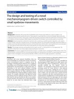
Design and fabricate a humanoid robot and build the walk trajectory
Bạn đang xem bản rút gọn của tài liệu. Xem và tải ngay bản đầy đủ của tài liệu tại đây (847.67 KB, 9 trang )
Design and fabricate a humanoid robot and build
the walk trajectory
Le, Thanh Quanga
a
Department of Mechatronics, University of Technical Education of Ho Chi Minh City,
VietNam, July, 2012
Abstract
To be able to calculate and control a
humanoid robot, one of the important
problems is modeling the robot. Modeling
is establishing a system by using the
performing mathematics, so that we will
have the core awareness for solving.
Some other requirements are response
times. Forward and inverse kinematic
equations for position and orientation use
more Sin, Cosin, Arcsin, Arccos
functions, which require more time to
calculate.
In addition, we need to calculate the
forward
kinematics
and
inverse
kinematics of the robot. Solving the
inverse kinematics is the basic and
complex problems, because we do not
have the typical methods, they deal more
with the number of degrees of freedom,
positions and orientation of end points
and the difficulty in solving the complex
mathematical equations.
I. Introductions
This project will design the mechanical part,
electrical part, software utility, design walk
trajectory and control a robot to walk like
this. We need six degrees of freedom (DOF)
to define one point or body in space,3 DOF
of position and 3 DOF for orientation, 3
DOF of position are determined by using the
coordinate system. With x, y, z coordinate, 3
DOF of orientation is described by rotary
This report will determine how to model
and resolve the forward and inverse
kinematics base on Denavit - Hartenberg
theory and adopt Levenberg-Marquardt
theory about numeric matrix to solve
forward and inverse kinematic equations
for position and orientation.
angle around the coordinate axis. There are
some version of humanoid robot are built
from the Ho Chi Minh City University of
Technology, Viet Nam. These versions have
the advantages of using harmonic gearbox,
which has the character of high ratio, error
reduction at output, friction reduction at
input. DC servo motor enclosed with one
encoder and one microchip.
These chips communicate together by using
CAN network. The disadvantages of them
are: heavy weight, spend more time to
calculate the trajectory directly.
So, we have the D-H tables for left and right
foot.
#
1
2
3
4
5
6
7
8
9
With modeling, they use translation matrixes
and rotary matrixes to demonstrate the
robot, and use analytic method for solving
the inverse kinematics.
In this project, we will use DenavidHartenberg theory to model the robot and
use numeric method for solving the inverse
kinematics. By using RC servo motor, this
has light weight, easy to control…
II.
L
0
L12
0
L34
L45
L56
L67
L78
L89
d
0
0
L23
0
0
0
0
0
0
a
0
90
-90
0
90
0
0
-90
0
t
0
0
0
0
Ɵ4
Ɵ5
Ɵ6
Ɵ7
Ɵ8
Tab 1. D-H table for left foot.
#
1
2
3
4
5
6
7
8
9
Results and Discussion
1. Modeling the robot:
We need to show how many degrees of
freedom the robot has?
l
0
L12
0
L10_11
L11_12
L12_13
L13_14
L14_15
L15_16
d
0
0
-L2_10
0
0
0
0
0
0
a
0
90
-90
0
90
0
0
-90
0
t
0
0
0
0
Ɵ11
Ɵ12
Ɵ13
Ɵ14
Ɵ15
Tab 2. D-H table for right foot.
Denevit – Hartenberg theory:[1]
Transposed matrix from N coordinate to
N+1 coordinate: n Tn1
Cn,n 1 Sn,n 1
S
Cn,n 1
n
Tn 1 n,n 1
0
0
0
0
0 ln 1Cn,n 1 lnCn
0 ln 1Sn,n 1 ln Sn
1
0
0
1
Transposed matrix from R coordinate to H
coordinate:
R
Fig 1. Modeling of robot.
Figure 1 indicates the typical modeling, in
real robot we have some angles do not
rotate. For walk trajectory, we will care of
the position and orientation of hip and feet.
Forward kinematic:
TH R T1.1T2 .2 T3...k Tk 1...n1TH A1.A2.A3...An
R: Reference
H: Hand of Robot
From the transposed matrix from R
coordinate to H coordinate:
nx
n
R
TH y
nz
0
ox
oy
ax
ay
oz
0
az
0
xA
y A
zA
1
Euler(Φ, Ɵ ,Ψ) = Rot(z,Φ). Rot(y,Ɵ). Rot(x,Ψ)=
CC C S S CC S S C CS
S C C CS S C S CC S S
Euler(, , )
S C
S S
C
0
0
0
Ca Co
S C
RPY(a , o , n ) a o
So
0
CaSoSn SaCn
SaSoS CaCn
CaSoCn SaSn
SaSoCn CaSn
CoSn
0
CoCn
0
Jacobi matrix:
We have the position of end point:
With a robot have 2 mechanisms:
Px x A
P y
y A
Pz z A
Inverse kinematic:
Position and orientation:
Fig 3. Two mechanisms robot.
Coordinate of B:
xB L1 Cos(1 ) L2Cos(1 2 )
y L Sin( ) L Sin( )
B 1
1
2
1
2
Fig 2. Position and orientation.
With the same position , but in above figure,
the orientation of A is different. We have the
forward kinematic equation of position and
orientation:
Differentiating this equation with respect to
the two variables Ɵ1, Ɵ2:
d xB L1Sin1 L2 Sin(1 2 ) d1
d yB L1Cos1 L2Cos(1 2 ) d2
We have Jacobi matrix:
TH T Px , Py , Pz . RPY Øa , Øo , Ø
n L1Sin1
R
TH T Px , Py , Pz . Euler Øa , Øo ,
n 1Cos1
ØL
R
L2 Sin(1 2 )
L2Cos(1 2 )
0
0
0
1
0
0
0
1
d xB
d1
Jacobi D J D
d yB
d2
D J 1 D
D J .D
D J 1.D
1
J X x
D
D X x
J 1.x
J 1.e
n J 1.e n 1
If we have inverse Jacobi matrix, we will
solve the inverse kinematics problem. But
Jacobi matrix is non-square matrix, we may
not calculate it. We attempt to find other
method to solve it. Levenberg-Marquardt
has published one method to calculate the
inverse matrix, which is not square matrix.
[2]
J T JJ T I dX
1
Fig 4. Algorithm of control
Start
Initializing of position and
orientation:
x, y, z x0 , y0 , z0
, , 0 , 0 , 0
2. Design walk trajectory:
In walking project, the orbit of hip and foot
must be ensuring like a human. So, we must
design the trajectory for hip and foot. At first
we need to find one point, which does not
change the position while walking. The orbit
of hip and foot are defined by the equation
of order 3
3
2
x(t)= a.t + b.t + c.t +
Calculate the errors:
We need to design walk trajectory in 2
e f Oyz.
f0
planes Oxy and set
J T JJ T I e
1
Fig 8. Chart of foot on zcoordinate
Fig 5. Trajectory of hip, foot on Oxy plane.
Fig 9.Chart of Hip on x coordinate.
Fig 6. Trajectory of hip, foot on Oyz plane.
Fig 10. Chart of Hip on y coordinate.
Fig 6.Chart of foot on x coordinate
Fig 6.Chart of Hip on coordinate.
Fig 7.Chart of foot on y coordinate
3. Mechanism[3]
To reach the accuracy in control, the
mechanical design of robot is complex,
difficult. Material of robot is aluminum,
using Solidwork software to design CAD
model . The RC servo motors were used.
Character of robot:
name
dimension
Agrees of
freedom
weigh
character
212x450x60
16
56g
Tab 3. D-H table for right foot.
4. Control:
Use a computer to calculate the value for
each step of walk project.. 2 dspic 30f6014A
chip to control these motors.
Dspic
30F6014A
(Master)
Fig 10. Full CAD model of robot
Dspic 30F6014A
(Slave)
Servo 1
Servo 9
Servo 2
Servo 10
Servo 3
Servo 11
Servo 4
Servo 12
Servo 5
Servo 13
Servo 6
Servo 14
Servo 7
Servo 15
Servo 8
Servo 16
Fig 12. Block of hardware
Fig 11. Assembly of robot
Fig 13. Electric hardware [4]
Simulation and experiment
Fig 14. Walking process in plane 1
Fig 15. Walking process in plane 2
Fig 16. Walking process in plane 3
1
2
3
11
12
13
4
5
14
6
15
7
16
8
17
9
18
10
19
Fig 17. Walking process in real
III.
Conclusions:
This project show the method to model,
solve the forward and inverse kinematic
equations of position and orientation.
Finding the way to calculate the inverse
kinematic with orientation is so important.
There are so many robot uses the
orientation in its act. In painting robot, the
hand of robot is always parallel with thing
need to paint. A serving robot handles a
glass of water, which is not fallen out…
The disadvantages of this project are: the
trajectories were designed before update
for chips permanently. Because of low
speed, these chips can not calculate the
trajectory as online process while robot is
walking. The mechanism parts, electronic
hardware were made by hand, the nonaccuracy motors had
The flexibility of this method help us to
develop the robot, which can go up stair,
down stair, walk on non -plane surface.
References
1.
2.
B.Niku, S., Introduction to Robotics
Analysis, Systems, Applications,
2001: United States of America.
Gavin, H., The LevenbergMarquardt method for
nonlinear least squares
curve-fitting problems. September
28,2011.
3.
CO..LTD, K.K., Hardware manual
KHR-1, K.K. CO..LTD, Editor
Sep.2004.
4.
High-Performance, -.b. and D.S.
Controllers,
dsPIC30F6011A/6012A/6013A/601
4A
Data Sheet, Mocrochip, Editor 2008.