tai lieu bien tan LS, Manual is7 151104
Bạn đang xem bản rút gọn của tài liệu. Xem và tải ngay bản đầy đủ của tài liệu tại đây (14.61 MB, 345 trang )
Thank you for purchasing LS Variable Frequency Drives!
SAFETY INSTRUCTIONS
To prevent injury and property damage, follow these instructions.
Incorrect operation due to ignoring instructions will cause harm or
damage. The seriousness of which is indicated by the following
symbols.
DANGER
This symbol indicates the instant death or
serious injury if you don’t follow instructions
WARNING
This symbol indicates the possibility of
death or serious injury
CAUTION
This symbol indicates the possibility of
injury or damage to property
■ The meaning of each symbol in this manual and on your equipment is as follows.
This is the safety alert symbol.
Read and follow instructions carefully to avoid dangerous situation.
This symbol alerts the user to the presence of “dangerous voltage”
inside the product that might cause harm or electric shock.
■ After reading this manual, keep it in the place that the user always can contact
easily.
■ This manual should be given to the person who actually uses the products and is
responsible for their maintenance.
i
WARNING
Do not remove the cover while power is applied or the unit is in operation.
Otherwise, electric shock could occur.
Do not run the inverter with the front cover removed.
Otherwise, you may get an electric shock due to high voltage terminals or charged capacitor
exposure.
Do not remove the cover except for periodic inspections or wiring, even if
the input power is not applied.
Otherwise, you may access the charged circuits and get an electric shock.
Wiring and periodic inspections should be performed at least 10 minutes
after disconnecting the input power and after checking the DC link voltage is
discharged with a meter (below DC 30V).
Otherwise, you may get an electric shock.
Operate the switches with dry hands.
Otherwise, you may get an electric shock.
Do not use the cable when its insulating tube is damaged.
Otherwise, you may get an electric shock.
Do not subject the cables to scratches, excessive stress, heavy loads or
pinching.
Otherwise, you may get an electric shock.
ii
CAUTION
Install the inverter on a non-flammable surface. Do not place flammable
material nearby.
Otherwise, fire could occur.
Disconnect the input power if the inverter gets damaged.
Otherwise, it could result in a secondary accident and fire.
Do not touch the inverter while the input power is applied or after removed. It
will remain hot for a couple of minutes.
Otherwise, you may get bodily injuries such as skin-burn or damage.
Do not apply power to a damaged inverter or to an inverter with parts
missing even if the installation is complete.
Otherwise, electric shock could occur.
Do not allow lint, paper, wood chips, dust, metallic chips or other foreign
matter into the drive.
Otherwise, fire or accident could occur.
OPERATING PRECAUTIONS
(1)
Handling and installation
Handle according to the weight of the product.
Do not stack the inverter boxes higher than the number recommended.
Install according to instructions specified in this manual.
Do not open the cover during delivery.
Do not place heavy items on the inverter.
Check the inverter mounting orientation is correct.
Do not drop the inverter, or subject it to impact.
Use the ground impedance of 100ohm or less for 200 V Class and 10ohm or less for 400V class.
Take protective measures against ESD (Electrostatic Discharge) before touching the PCB for
inspection or installation.
Use the inverter under the following environmental conditions:
iii
Environment
Ambient temp.
Relative humidity
Storage temp.
Location
Altitude, Vibration
Atmospheric pressure
(2)
Wiring
(3)
Do not connect a power factor correction capacitor, surge suppressor, or RFI filter to the output of
the inverter.
The connection orientation of the output cables U, V, W to the motor will affect the direction of
rotation of the motor.
Incorrect terminal wiring could result in the equipment damage.
Reversing connection of the input/output terminals(R,S,T / U,V,W) could damage the inverter.
Only authorized personnel familiar with LS inverter should perform wiring and inspections.
Always install the inverter before wiring. Otherwise, you may get an electric shock or have bodily
injury.
Trial run
(4)
Check all parameters during operation. Changing parameter values might be required depending
on the load.
Always apply permissible range of voltage to the each terminal as indicated in this manual.
Otherwise, it could lead to inverter damage.
Operation precautions
iv
CT Load: - 10 ~ 50℃ (non-freezing)
VT Load: -10 ~ 40℃(non-freezing)
Note: Use below 80% of load when used under VT
Load at 50℃
90% RH or less (non-condensing)
- 20 ~ 65 ℃
Protected from corrosive gas, combustible gas, oil
mist or dust (Pollution degree 2 environment)
Max. 1,000m above sea level, Max. 5.9m/sec2
(0.6G) or less
70 ~ 106 kPa
When the Auto restart function is selected, stay away from the equipment as a motor will restart
suddenly after an alarm stop.
The Stop key on the keypad is valid only when the appropriate function setting has been made.
Prepare an emergency stop switch separately.
If an alarm reset is made with the reference signal present, a sudden start will occur. Check that
the reference signal is turned off in advance. Otherwise an accident could occur.
Do not modify or alter anything inside the inverter.
Motor might not be protected by electronic thermal function of inverter.
Do not use a magnetic contactor on the inverter input for frequent starting/stopping of the inverter.
Use a noise filter to reduce the effect of electromagnetic interference. Otherwise nearby electronic
equipment may be affected.
In case of input voltage unbalance, install AC reactor. Power Factor capacitors and generators may
become overheated and damaged due to potential high frequency noise transmitted from inverter.
(5)
Use an insulation-rectified motor or take measures to suppress the micro surge voltage when
driving 400V class motor with inverter. A micro surge voltage attributable to wiring constant is
generated at motor terminals, and may deteriorate insulation and damage motor.
Before operating unit and prior to user programming, reset user parameters to default settings.
Inverter can easily be set to high-speed operations, Verify capability of motor or machinery prior to
operating unit.
Stopping torque is not produced when using the DC-Break function. Install separate equipment
when stopping torque is needed.
Fault prevention precautions
(6)
Provide a safety backup such as an emergency brake which will prevent the machine and
equipment from hazardous conditions if the inverter fails.
Maintenance, inspection and parts replacement
(7)
Do not conduct a megger (insulation resistance) test on the control circuit of the inverter.
Refer to Chapter 12 for periodic inspection (parts replacement).
Disposal
(8)
Handle the inverter as an industrial waste when disposing of it.
General instructions
Many of the diagrams and drawings in this instruction manual show the inverter without a circuit
breaker, a cover or partially open. Never run the inverter like this. Always place the cover with
circuit breakers and follow this instruction manual when operating the inverter.
v
Introduction to the Manual
Introduction to the Manual
This manual describes the specifications, installation, operation, functions and maintenance of SV-iS7 series inverter
and is for the users who have basic experience of using an inverter.
It is recommended you read carefully this manual in order to use SV-iS7 series inverter properly and safely.
The manual consists as follows.
Chapter
Title
Contents
1
Basics
Describes the precautions and basic items which should be learned before using the
Inverter.
2
Specifications
The control specifications, ratings and types of the input and output
3
Installation
Information on the use environment and installation method.
4
Wiring
Wiring information for the power supply and signal terminals.
Peripheral
Devices
How To Use
Keypad
Peripheral devices which can be connected with the input and output terminals of the
Inverter
5
6
Descriptions on the display and operation keys on the main body of the Inverter.
7
Basic Functions
Descriptions on the basic functions including frequency setting and operation
command.
8
Applied Functions
Descriptions on the functions required for system application.
9
Monitor Functions
Information on the operational status and troubles of the Inverter.
10
11
12
Protective
Functions
Communication
Functions
Checking &
Troubleshooting
Describes the protective functions for the motor and Inverter.
The specifications of the RS-485 communication.
Descriptions on the failures and anomalies which may occur during operation.
13
Table of Functions
Brief summarize of functions.
14
Safety Functions
Descriptions on the safety standard products and safety fucntion
15
Classification
Product
Information on the products of classification standard.
i
Contents
Chapter 1
1.1
Basics
What You Should Know before Use
---------------------
1-1
1.1.1
Checking of product
---------------------
1-1
1.1.2
Parts
---------------------
1-2
1.1.3
Preparation of device and Parts for operation
---------------------
1-2
1.1.4
Installation
---------------------
1-2
1.1.5
Distribution
---------------------
1-2
Names and Uses of Parts
---------------------
1-3
1.2.1
End product (not more than 75 kW)
---------------------
1-3
1.2.2
When the front cover is removed (not more
--------------------than 75kW)
1-3
1.2.3
End product (more than 90kW)
---------------------
1-4
1.2.4
When the front cover is removed (more than
--------------------90kW)
1-4
1.2
Chapter 2
2.1
Specifications
Specifications
---------------------
2-1
2.1.1
Rated Input and Output: Input voltage of 200V
--------------------class (0.75~22kW)
2-1
2.1.2
Rated Input and Output: Input voltage of 200V
--------------------class (30~75kW)
2-1
2.1.3
Rated Input and Output : Input voltage of 400V
--------------------class (0.75~22kW)
2-2
2.1.4
Rated Input and Output : Input voltage of 400V
- - -- - - - - - - - - - - - - - - - - class (30~160kW)
2-3
2.1.5
Rated Input and Output : Input voltage of 400V
- - -- - - - - - - - - - - - - - - - - class (185~375kW)
2-3
2.1.6
Other commons
2-3
---------------------
i
Contents
Chapter 3
3.1
Installation
---------------------
3-1
3.1.1
Cautions before installation
---------------------
3-2
3.1.2
Exterior and Dimension
(UL Enclosed Type 1, IP21 Type)
---------------------
3-4
3.1.3
External dimension
(UL Enclosed Type12, IP54 Type)
---------------------
3-18
3.1.4
Dimension and Weight of frame
(UL Enclosed Type 1, IP21 Type)
---------------------
3-22
3.1.5
Dimension and Weight of Frame
(UL Enclosed Type 12, IP54 Type)
---------------------
3-23
3.1.6
Installation Guide
(UL Enclosed Type12, IP54 Type)
---------------------
3-24
Wiring
---------------------
4-1
4.1.1
How to separate front cover when wiring
(below 75kW)
---------------------
4-3
4.1.2
How to separate front cover when wiring
(90~160 kW)
---------------------
4-5
4.1.3
Built-in EMC Filter
---------------------
4-6
4.1.4
Wiring precaution
---------------------
4-8
4.1.5
Grounding
---------------------
4-8
4.1.6
Terminal wiring diagram
(Power terminal block)
---------------------
4-9
4.1.7
Terminals of main circuit
---------------------
4-11
Chapter 4
4.1
4.1.8
4.1.9
4.1.10
ii
Installation
Wiring
Specifications of power terminal block and
--------------------Exterior fuse
Control terminal line diagram
--------------------(Basic I/O terminal block, below 22kW
products)
Control terminal line diagram
--------------------(Insulated I/O terminal block, above 30kW
products)
4-15
4-18
4-21
Contents
4.1.11
4.1.12
4.1.13
4.1.14
Control circuit terminal
Specifications of signal terminal block
distribution
Input varistor and Y-CAP connection
description
How to remove the front cover and set up
on/off connector functionality
---------------------
4-23
---------------------
4-21
---------------------
4-26
---------------------
4-26
4.1.15
The grounded ON/OFF connection removal
---------------------
4-27
4.2
Operation Checking
---------------------
4-28
4.2.1
Easy start
---------------------
4-28
4.2.2
Easy start operation
---------------------
4-28
4.2.3
Checking for normal working
---------------------
4-29
Peripheral Devices
---------------------
5-1
5.1.1
Composition of peripheral devices
---------------------
5-1
5.1.2
Specifications of wiring switch, Electronic
--------------------contactor and Reactor
5-2
5.1.3
Dynamic breaking unit (DBU) and Resistors
---------------------
5-5
How To Use Keypad
---------------------
6-1
6.1.1
Standard KEYPAD appearance and
description (Graphic keypad)
---------------------
6-1
6.1.2
Menu composition
---------------------
6-6
6.1.3
Mode shift
---------------------
6-8
6.1.4
Group shift
---------------------
6-10
6.1.5
Code (Function item) shift
---------------------
6-12
6.1.6
Parameter setting
---------------------
6-15
Chapter 5
5.1
Chapter 6
6.1
Peripheral Devices
How To Use Keypad
iii
Contents
6.1.7
Operating status monitoring
---------------------
6-17
6.1.8
Failure status monitoring
---------------------
6-20
6.1.9
How to initialize parameters
---------------------
6-22
Basic Functions
---------------------
7-1
7.1.1
How to set frequency
---------------------
7-1
7.1.2
Analog command frequency fixation
---------------------
7-8
7.1.3
Changing frequency display to RPM
---------------------
7-9
7.1.4
Sequential frequency setting
---------------------
7-9
7.1.5
Operating command setting method
---------------------
7-10
7.1.6
Local/Remote by-pass operation using multifunction keys
---------------------
7-12
7.1.7
Prevention of forward or reverse rotation: Run
--------------------Prevent
7-14
7.1.8
Run Immediately with power on: Power-on
Run
---------------------
7-14
7.1.9
Restarts by reset after trip: RST Restart
---------------------
7-15
7.1.10
Setting of accelerating/decelerating time and
pattern
---------------------
7-15
7.1.11
Acc/Dec pattern setting
---------------------
7-18
7.1.12
Acc/Dec stop command
---------------------
7-20
7.1.13
V/F voltage control
---------------------
7-20
7.1.14
Torque boost
---------------------
7-22
7.1.15
Motor output voltage adjustment
---------------------
7-23
7.1.16
Selection of starting method
---------------------
7-23
Chapter 7
7.1
iv
Basic Functions
Contents
7.1.17
Stop method selection (Changing stop
---------------------
7-24
method)
7.1.18
Stop after D.C. braking
---------------------
7-25
7.1.19
Frequency limit
---------------------
7-26
7.1.20
Selection of second operating method (By---------------------
7-28
---------------------
7-29
---------------------
7-29
---------------------
8-1
8.1.1
Override frequency setting using auxiliary
--------------------frequency command
8-1
8.1.2
Jog operation
---------------------
8-4
8.1.3
UP-DOWN operation
---------------------
8-6
8.1.4
3-WIRE operation
---------------------
8-8
8.1.5
Safe operation mode
---------------------
8-9
8.1.6
Dwell operation
---------------------
8-10
8.1.7
Slip compensation operation
---------------------
8-12
8.1.8
PID control
---------------------
8-13
8.1.9
Auto tuning
---------------------
8-18
8.1.10
V/F operation using speed sensor
---------------------
8-21
8.1.11
Sensorless(I) vector control
---------------------
8-22
8.1.12
Sensorless(II) vector control
---------------------
8-24
8.1.13
Vector control
---------------------
8-28
8.1.14
Torque control
---------------------
8-32
pass operation)
7.1.21
Multi-function input terminal control
(Improving responsiveness of input terminal)
7.1.22
Chapter 8
8.1
Digital input and output control by extended
I/O option card
Applied Functions
Applied Functions
v
Contents
vi
8.1.15
Droop control
---------------------
8-34
8.1.16
Speed/Torque change function
---------------------
8-34
8.1.17
Kinetic energy buffering
---------------------
8-34
8.1.18
Energy saving operation
---------------------
8-37
8.1.19
Speed search operation
---------------------
8-38
8.1.20
Automatic restart
---------------------
8-40
8.1.21
Operation sound selection
---------------------
8-41
8.1.22
2nd Motor operation
---------------------
8-43
8.1.23
By pass operation
---------------------
8-44
8.1.24
Cooling fan control
---------------------
8-45
8.1.25
Input power frequency selection
---------------------
8-46
8.1.26
Inverter input voltage selection
---------------------
8-46
8.1.27
Parameter writing and reading
---------------------
8-46
8.1.28
Parameter initialization
---------------------
8-47
8.1.29
Parameter view lock and Key lock
---------------------
8-47
8.1.30
Addition to User Group (USR Grp)
---------------------
8-49
8.1.31
Addition to Macro Group
---------------------
8-50
8.1.32
Easy start
---------------------
8-50
8.1.33
Other Config(CNF) mode parameters
---------------------
8-51
8.1.34
Timer function
---------------------
8-49
8.1.35
Auto sequence operation
---------------------
8-52
8.1.36
Traverse operation
---------------------
8-55
8.1.37
Brake control
---------------------
8-56
8.1.38
Multi-function output On/Off control
---------------------
8-59
8.1.39
MMC function
---------------------
8-59
Contents
8.1.40
Regeneration evasion function for press
---------------------
8-64
8.1.41
Anti-Hunting Regulator
---------------------
8-65
8.1.42
Fire Mode
---------------------
8-65
8.1.43
Braking(DB)
voltage
---------------------
8-67
Monitor Functions
---------------------
9-1
9.1.1
Monitor in operation - Keypad
---------------------
9-1
9.1.2
Failure status monitor – Keypad
---------------------
9-4
9.1.3
Analog output
---------------------
9-6
9.1.4
Selection of relay function and multi-function
--------------------output terminal of terminal block
9-12
9.1.5
Failure status output by relay and multi--------------------function Output terminal of terminal block
9-17
9.1.6
Output terminal delay time and type of contact
--------------------point
9-18
9.1.7
Operating time monitor
---------------------
9-18
9.1.8
Selection of keypad language
---------------------
9-19
Chapter 9
9.1
resistor
operation
reference
Monitor Functions
Chapter 10 Protective Functions
10.1
Protective Functions
---------------------
10-1
10.1.1
Motor protection
---------------------
10-1
10.1.2
Overload warning and troubleshooting (Trip)
---------------------
10-2
10.1.3
Stall prevention and Flux braking
---------------------
10-3
10.1.4
Motor overheat sensor input
---------------------
10-5
10.1.5
Inverter and sequence protection
---------------------
10-6
10.1.6
External failure signal
---------------------
10-7
10.1.7
Inverter overload
---------------------
10-8
10.1.8
Keypad command loss
---------------------
10-8
vii
Contents
10.1.9
Braking resistance use rate setting
---------------------
10-10
10.1.10
Underload warning and failure
---------------------
10-11
10.1.11
Overspeed error
---------------------
10-12
10.1.12
Speed variation failure
---------------------
10-12
10.1.13
Speed sensor error detection
---------------------
10-12
10.1.14
Fan failure detection
---------------------
10-12
10.1.15
Selection of action in case of low voltage
failure
---------------------
10-13
10.1.16
Output blocking by multi-function terminal
---------------------
10-13
10.1.17
How to terminate failure state
---------------------
10-13
---------------------
10-14
---------------------
10-14
10.1.18
10.1.19
Selection of action in case of option card
failure
Detection of motor not connected to inverter
output terminal
10.1.20
Select ‘Low Viltage2’ during operation
---------------------
10-14
10.1.21
Table of failures/warnings
---------------------
10-15
Communication Functions
---------------------
11-1
11.1.1
Introduction
---------------------
11-1
11.1.2
Specifications
---------------------
11-2
11.1.3
Composition of communication system
---------------------
11-2
11.1.4
Basic setting
---------------------
11-3
11.1.5
Operating command and frequency setting
---------------------
11-4
11.1.6
Command loss protection
---------------------
11-4
11.1.7
Virtual multi-function input setting
---------------------
11-4
11.1.8
Caution in parameter setting for
communication
---------------------
11-5
11.1.9
Communication frame monitoring
---------------------
11-5
11.1.10
Special communication area setting
---------------------
11-6
Chapter 11 Communication Functions
11.1
viii
Contents
11.1.11
Parameter group for periodical data
transmission
---------------------
11-7
11.1.12
Parameter group for transmission of Macro
Grp and U&M Mode User
---------------------
11-8
Communication protocol
---------------------
11-9
11.2.1
LS INV 485 protocol
---------------------
11-9
11.2.2
Detailed reading protocol
---------------------
11-10
11.2.3
Detailed writing protocol
---------------------
11-11
11.2.4
Monitor registration detailed protocol
---------------------
11-11
11.2.5
Modbus-RTU protocol
---------------------
11-13
11.2.6
Existing iS5/iG5/iG5A compatible common
area parameter
---------------------
11-16
11.2.7
iS7 extended common area parameter
---------------------
11-20
Checking and troubleshooting
---------------------
12-1
12.1,1
Protective functions
---------------------
12-1
12.1.2
Alarm functions
---------------------
12-3
12.1.3
Troubleshooting
---------------------
12-4
12.1.4
Replacement of cooling fan
---------------------
12-6
12.1.5
Daily and regular checkup list
---------------------
12-8
Table of Functions
---------------------
13-1
13.1.1
Parameter mode – DRV group (DRV)
---------------------
13-1
13.1.2
Parameter mode – Basic function group
---------------------
13-3
---------------------
13-7
11.2
Chapter 12 Checking and Troubleshooting
12.1
Chapter 13 Table of Functions
13.1
(BAS)
13.1.3
Parameter mode – Parameter mode –
Extended function group (PARADV)
ix
Contents
13.1.4
Parameter mode – Control function group
(CON)
---------------------
13-11
13.1.5
Parameter mode – Input terminal block
function group (IN)
---------------------
13-17
13.1.6
Parameter mode – Output terminal block
function group (OUT)
---------------------
13-21
13.1.7
Parameter mode – Communication function
group (COM)
---------------------
13-25
13.1.8
Parameter mode – Applied function group
(APP)
---------------------
13-28
13.1.9
Parameter mode – Auto sequence operation
group (AUT)
---------------------
13-31
13.1.10
Parameter mode – Option card function group
--------------------(APO)
13-34
13.1.11
Parameter mode – Protective function group
--------------------(PRT)
13-37
13.1.12
Parameter mode – 2nd motor function group
--------------------(M2)
13-40
13.1.13
Trip mode (TRP Current (or Last-x))
---------------------
13-41
13.1.14
Config mode (CNF)
---------------------
13-41
13.1.15
13.1.16
User/Macro mode – Draw operation function
--------------------group MC1
User/Macro mode – Traverse operation
--------------------function group (MC2)
13-44
13-45
Chapter 14 Functional Safety
14.1
Functional Safety
---------------------
14-1
14.1.1
Safety Standard product
---------------------
14-1
14.1.2
Safety function description and wiring
---------------------
14-1
---------------------
15-1
diagram
Chapter 15 Classification Product
15.1
x
Classification Product
Contents
15.1.1
Classification Standard
---------------------
15-1
15.1.2
Classification standard acquisition
---------------------
15-1
15.1.3
Classification Model SV-iS7 Products
---------------------
15-1
Chapter 16 Single-Phase Rating
16.1
Introduction
---------------------
16-1
16.1,1
Power(HP), Input Current and Output Current
---------------------
16-2
16.1.2
Input Frequency and Voltage Tolerance
---------------------
16-2
16.1.3
Wiring and Peripheral Device
---------------------
16-2
16.1.4
Considerations When Using a Three-Phase
---------------------
16-4
Drive with Single-Phase Input
xi
Chapter 1 Basics
1.1 What You Should Know before Use
1.1.1 Checking of product
Take the inverter out of the box, check the rating shown on a side of the product body and whether the inverter type
and rated output are exactly what you ordered. Check also whether or not the product has been damaged during
delivery.
008
iS7
Capacity of Applied Motor
VT
CT
(Normal duty) (Heavy duty)
0008 1 1.5 [kW]
0.75 [kW]
.
0015
2.2 [kW]
1.5 [kW]
5
0022
3.7 [kW]
2.2 [kW]
INV
Model
L S Inverter
0037 [ 5.5
0055 k 7.5
0075 W 11
]
0110
15
[kW]
3.7 [kW]
[kW]
5.5 [kW]
[kW]
7.5 [kW]
[kW]
11
[kW]
0150
18.5 [kW]
15
[kW]
0185
22
[kW]
18.5 [kW]
0220
30
[kW]
22
[kW]
0300
37
[kW]
30
[kW]
0370
45
[kW]
37
[kW]
0450
55
[kW]
45
[kW]
0550
75
[kW]
55
[kW]
0750
90
[kW]
75
[kW]
0900
110 [kW]
90
[kW]
1100
132 [kW]
110 [kW]
1320
160 [kW]
132 [kW]
1600
185 [kW]
160 [kW]
1850
220 [kW]
185 [kW]
2200
280 [kW]
220 [kW]
2800
315 [kW]
280 [kW]
3150
375 [kW]
315 [kW]
3750
450 [kW]
375 [kW]
Series
Name
-
2
N
O
F
D
W
Input Voltage
Keypad
UL
EMC
DCR
Specific
Product
2:
3-Phase
200~230[V]
Wide-Use Inverter
SV
4:
3-Phase
- 380~480[V]
Blank:
NonEMC
N:
NON
O:
OPEN
S:
GLCD
(Graphic
Loader)
E:
F:
Enclosed UL EMC
Type1
Blank:
W:
Non-DCR Web
D:
DCR
S:
Synchro
note 1)
P:
Enclosed UL
Type 12
R:
T:
DB
Safety
Resistor
(Inner
Mounted)
V:
Classificati
on
Note1)
Enclosed UL Type 1 has the conduit option additionally at 0.75 through 75 kW products.
Note2)
DB Resistor of IS7 Product is the option of WEB product. Applicable capacity is from 0.75 to 375 kW of IS7
products.
1-1
Chapter 1 Basics
1.1.2 Parts
If you have any doubt about the product or found the product damaged, call our company’s branch offices(see the
back cover of the manual).
1.1.3 Preparation of device and Parts for operation
Preparation for operation may slightly vary. Prepare parts according to the use.
1.1.4 Installation
Make sure you install the product correctly considering the place, direction or surroundings in order to prevent
decrease in the life and performance of the inverter.
1.1.5 Distribution
Connect the power supply, electric motor and operating signals(control signals) to the terminal block. If you fail to
connect them correctly, the inverter and peripheral devices may be damaged.
1-2
Chapter 1 Basics
1.2 Names and Uses of Parts
1.2.1 End product (not more than 75 kW)
Keypad
Front cover::
Remove it when wiring
Volt for front cover to fix
Wiring bracket
Ground terminal
Cooling FAN
1.2.2 When the front cover is removed (not more than 75 kW)
Keypad connection
terminal
communication option
connection part
Inverter condition
display BAR
Encoder option
Power terminal
PLC, extension I/O,
communication option
connection part
I/O board & terminal
Wiring bracket
1-3
Chapter 1 Basics
1.2.3 End Product (more than 90kW)
Keypad
Volt for upper front
cover to fix (left side)
Volt for lower front
cover to fix (left side)
Cooling fan
Upper front cover
Volt for upper front
cover to fix (right side)
Lower front cover
Volt for lower front
cover fix (right side)
Power input
Signal input
Ground
1.2.4 When the front cover is removed (more than 90kW)
SCR snubber circuit
Communication option
board connection part
Encoder option board
Keypad connection
terminal
I/O board and terminal
FAN SMPS circuit
Main SMPS circuit
Inverter condition display
LED
PLC, Extension I/O,
Communication option
Connection part
Shield plate
Safety option board
(Selectable function)
Remark
Please refer to relevant manual for option board relations..
1-4
Power Busbar (R/S/T, U/V/W, P/N)
Chapter 2 Specifications
2.1 Specifications
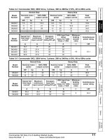
2.1.1 Rated Input and Output : Input voltage of 200V class (0.75~22kW)
Type : SV xxx iS7 – 2x
0008
0015
0022
0037
0055
0075
0110
0150
0185
0220
[HP]
2
3
5
7.5
10
15
20
[kW]
1.5
2.2
3.7
5.5
7.5
11
15
Motor
Applied
[HP]
1
2
3
5
7.5
10
15
CT
[kW]
0.75
1.5
2.2
3.7
5.5
7.5
11
2)
Rated Capacity
1.9
3.0
4.5
6.1
9.1
12.2
17.5
[kVA]
3)
VT
8
12
16
24
32
46
60
Rated
Current[A] CT
5
8
12
16
24
32
46
Output
4)
0 ~ 400 [Hz]
Frequency
Output Voltage 5) 3-phase 200 ~ 230V
[V]
(Sensorless-1:0~300Hz, Sensorless-2,Vector:0.1~120Hz)
Available Voltage
3-phase 200 ~ 230 VAC (-15%,+10%,)
[V]
Input Frequency 50 ~ 60 [Hz] (5%)
VT
6.8
10.6
14.9
21.3
28.6
41.2
54.7
Rated
Current [A] CT
4.3
6.9
11.2
14.9
22.1
28.6
44.3
25
18.5
20
15
30
22
25
18.5
40
30
30
22.9
28.2
33.5
74
60
88
74
124
88
69.7
55.9
82.9
70.8
116.1
85.3
VT
Rated Input
Rated Output
1)
22
* Non DCR products are provided warranty service when used in CT (Heavy duty) load rating only.
2.1.2 Rated Input and Output : Input voltage of 200V class (30~75kW)
Type : SV xxx iS7 – 2x
1)
Motor
Applied
VT
CT
0300
0370
0450
0550
0750
-
-
-
-
-
[HP]
50
60
75
100
120
[kW]
37
45
55
75
90
[HP]
40
50
60
75
100
[kW]
30
37
45
55
75
-
-
-
-
-
46
57
69
84
116
-
-
-
-
-
146
180
220
288
345
-
-
-
-
-
116
146
180
220
288
-
-
-
-
-
2)
Rated Capacity
Rated Output
[kVA]
3)
Rated
VT
Current[A]
CT
Output
4)
Frequency
(Sensorless-1:0~300Hz, Sensorless-2,Vector:0.1~120Hz)
Output Voltage
5)
[V]
Rated Input
Available Voltage
[V]
Input Frequency
0 ~ 400 [Hz]
3-phase 200 ~ 230V
3-phase 200 ~ 230 VAC (-15%~+10%)
50 ~ 60 [Hz] (5%)
Rated
VT
152
190
231
302
362
-
-
-
-
-
Current [A]
CT
121
154
191
233
305
-
-
-
-
-
* Non DCR products are provided warranty service when used in CT (Heavy duty) load rating only.
2-1
Chapter 2 Specifications
2.1.3 Rated Input and Output : Input voltage of 400V class (0.75~22kW)
Type : SV xxx iS7 – 4x
[HP]
[kW]
Motor
Applied
[HP]
CT
[kW]
2)
Rated Capacity
[kVA]
3)
VT
Rated
Current[A]
CT
Rated Input
Rated Output
1)
VT
Output Frequency
0008
0015
0022
0037
0055
0075
0110
0150
0185
0220
2
1.5
1
0.75
3
2.2
2
1.5
5
3.7
3
2.2
7.5
5.5
5
3.7
10
7.5
7.5
5.5
15
11
10
7.5
20
15
15
11
25
18.5
20
15
30
22
25
18.5
40
30
30
22
1.9
3.0
4.5
6.1
9.1
12.2
18.3
22.9
29.7
34.3
39
30
45
39
61
45
35.5
26.6
41.1
35.6
55.7
41.6
4
6
8
12
16
24
30
2.5
4
6
8
12
16
24
4)
0 ~ 400 [Hz]
(Sensorless-1: 0~300Hz, Sensorless-2, Vector: 0.1~120Hz)
5)
3-phase 380 ~ 480V
Output Voltage [V]
Available Voltage
3-phase 380 ~ 480 VAC (-15%~+10%)
[V]
Input Frequency
50 ~ 60 [Hz] (5%)
VT
3.7
5.7
7.7
11.1
14.7
Rated
Current [A]
CT
2.2
3.6
5.5
7.5
11.0
21.9
14.4
26.4
22.0
* Non DCR products are provided warranty service when used in CT (Heavy duty) load rating only.
2.1.4 Rated Input and Output : Input voltage of 400V class (30~160kW)
Type : SV xxx iS7 – 4x
[HP]
[kW]
Motor
Applied
[HP]
CT
[kW]
2)
Rated Capacity
[kVA]
3)
VT
Rated
Current[A]
CT
Rated Input
Rated Output
1)
VT
Output Frequency
0300
0370
0450
0550
0750
0900
1100
1320
1600
-
50
37
40
30
60
45
50
37
75
55
60
45
100
75
75
55
120
90
100
75
150
110
120
90
180
132
150
110
225
160
180
132
250
185
225
160
-
46
57
69
84
116
139
170
201
248
-
75
91
110
152
183
223
264
61
75
91
110
152
183
223
4)
0 ~ 400 [Hz]
(Sensorless-1: 0~300Hz, Sensorless-2, Vector: 0~120Hz)
5)
3-phase 380 ~ 480V
325
264
370
325
-
315.3
255.6
359.3
316.3
Output Voltage [V]
Available Voltage
3-phase 380 ~ 480 VAC (-15%, +10%)
[V]
Input Frequency
50 ~ 60 [Hz] (5%)
VT
67.5
81.7
101.8 143.6 173.4
Rated
Current[A]
CT 55.5
67.9
82.4
102.6 143.4
212.9
174.7
254.2
213.5
* Non DCR products are provided warranty service when used in CT (Heavy duty) load rating only.
2-2
Chapter 2 Specifications
2.1.5 Rated Input and Output : Input voltage of 400V class (185~375kW)
Type : SV xxx iS7 – 4x
1850
2200
2800
3150
3750
-
-
-
-
-
[HP]
300
375
420
500
600
-
-
-
-
-
[kW]
220
280
315
375
450
-
-
-
-
-
[HP]
250
300
375
420
500
-
-
-
-
-
[kW]
185
220
280
315
375
-
-
-
-
-
Rated Capacity [kVA]
286
329
416
467
557
-
-
-
-
-
VT
432
547
613
731
877
-
-
-
-
-
CT
370
432
547
613
731
-
-
-
-
-
VT
1)
Motor Applied
CT
Rated Output
2)
3)
Rated Current[A]
4)
Output Frequency
Rated Input
Output Voltage [V]
Available Voltage [V]
Input Frequency
0 ~ 400 [Hz]
(Sensorless-1:0~300Hz, Sensorless-2,Vector:0~120Hz)
5)
3-phase 380 ~ 480V
3-phase 380 ~ 480 VAC (-15%, +10%)
50 ~ 60 [Hz] (5%)
VT
463
590
673
796
948
-
-
-
-
-
CT
404
466
605
674
798
-
-
-
-
-
Rated Current[A]
1) Motor Applied indicates the maximum capacity applied to use of a standard 4 pole standard motor.
2) Rated capacity : the input capacity of a 200V class is based on 220V and that of a 400V class is based on 440V. The current
rating is based on CT current.
3) The output of rated current is limited according to setting of the carrier frequency (CON-04).
4) In case of Sensorless-1, you can set the frequency at up to 300Hz by selecting 3, 4 as the control mode (DRV-09 Control Mode).
In case of Sensorless-2, you can set the frequency at up to 120Hz by selecting 3, 4 as the control mode (DRV-09 Control Mode).
5) The maximum output voltage does not go up over the supplied power voltage. You can select the output voltage as you want
below the supplied power voltage.
2.1.6 Other commons
1) Control
Control Method
V/F control, V/F PG, slip compensation, sensorless vector-1, sensorless vector-2,
vector control
Frequency Setting
Resolving Power
Digital command : 0.01Hz
Analog command : 0.06Hz (maximum frequency : 60Hz)
Frequency Degree
Digital command operation : 0.01% of the maximum frequency
Analog command operation : 0.1% of the maximum frequency
V/F Pattern
Overload Capacity
Torque Boost
Linear, double reduction, user V/F
CT current rating :150% for 1 minute, VT current rating :110% for 1 minute
Manual torque boost, Automatic torque boost
* Non DCR products are provided warranty service when used in CT (Heavy duty) load rating only.
2-3
Chapter 2 Specifications
2) Operation
Operating Method
Frequency Setting
Operating Function
Selectable among keypad/terminal block/communication operation
Analog: 0 ~ 10[V], -10 ~ 10[V], 0 ~ 20[mA]
Digital: keypad
PID control, up-down operation, 3-wire operation, DC break, Frequency limit,
Frequency jump, Second function, Slip compensation, Reverse rotation prevention,
Auto restarting, Inverter By-pass, Auto tuning Flying Start, Energy buffering, Power
breaking, Flux breaking, Leakage current reduction, MMC, Easy Start.
NPN (Sink) / PNP (Source) selectable
Multi-function
terminal
(8 points)
P1 ~ P81)
Input
Output
Function: forward operation, reverse operation, reset, external trip, emergency stop,
jog operation, sequential frequency-high/medium/low, multi - level acceleration and
deceleration – high/medium/low, D.C. control during stop, selection of a second motor,
frequency increase, frequency decrease, 3-wire operation, change to general operation
during PID operation, Main inverter body operation during option operation, analog
command frequency fixation, acceleration and deceleration stop selectable.
Multi-function
open collector
terminal
Multi-function
relay terminal
Failure output and inverter operation
output
Analog output
0 ~ 10 Vdc, 0 ~ 20[mA] : selectable from frequency, current, voltage, direct current
voltage
Below DC 46V 100mA
Below (N.O., N.C.) AC250V 1A,
Below DC 30V 1A
1) The Functions for Multi-function terminal available according to IN-65~72 parameter setting of IN Group.
3) Protective Function
Trip
Alarm
Instantaneous
Interruption2)
over voltage, low voltage, over current, earth current detection, inverter overheat,
motor overheating, output imaging, overload protection, communication error,
frequency command loss, hardware failure, cooling fan failure, pre-PID failure, no
motor trip, external break trip. etc
Stall prevention, overload, light load, encoder error, fan failure, keypad command
loss, speed command loss.
Below CT class 15 msec (VT class 8 msec) : operation continues
(within rated input voltage, rated output)
Over CT class 15 msec (VT class 8 msec) : automatically restarts
2) Operation at the CT (Heavy Duty) current rating
4) Structure and Use Environment
Cooling Method
Protection Structure
Ambient Temperature
2-4
Forced cooling : 0.75~15kW (200/400V class), 22kW (400V class)
Inhalation cooling : 22~75kW (200V class), 30~375kW (400V class)
- 0.75~22kW(200V), 0.75~75kW(400V): Open type IP 21 (default), UL enclosed type
1 (Option) 3)
- 30~75kW (200V), 90~375kW(400V): Open type IP 00 (default),
UL enclosed type 1 (Option) 3)
- 0.75~22kW-2/4 and etc.: Enclosed IP54 type, UL enclosed type 12
- CT (Heavy Duty) load : - 10 ~ 50℃ (without ice or frost)
- VT (Normal Duty) load : - 10~ 40℃ (without ice or frost)
(It is recommended that you use less than 80% load when you use VT load at 50℃.)
- IP54 product: -10~40 ℃ (without ice or frost)