Ebook TCPIP essentials A LabBased approach Part 2
Bạn đang xem bản rút gọn của tài liệu. Xem và tải ngay bản đầy đủ của tài liệu tại đây (1.14 MB, 152 trang )
6
TCP study
The flow on a TCP connection should obey a ‘conservation of packets’ principle.
· · · A new packet isn’t put into the network until an old packet leaves.
Van Jacobson
6.1 Objectives
r
r
r
r
r
r
r
r
TCP connection establishment and termination.
TCP timers.
TCP timeout and retransmission.
TCP interactive data flow, using telnet as an example.
TCP bulk data flow, using sock as a traffic generator.
Further comparison of TCP and UDP.
Tuning the TCP/IP kernel.
Study TCP flow control, congestion control, and error control using DBS
and NIST Net.
6.2 TCP service
TCP is the transport layer protocol in the TCP/IP protocol family that provides a connection-oriented, reliable service to applications. TCP achieves
this by incorporating the following features.
r Error control: TCP uses cumulative acknowledgements to report lost
segments or out of order reception, and a time out and retransmission
mechanism to guarantee that application data is received reliably.
r Flow control: TCP uses sliding window flow control to prevent the receiver buffer from overflowing.
111
112
TCP study
r Congestion control: TCP uses slow start, congestion avoidance, and fast
retransmit/fast recovery to adapt to congestion in the routers and achieve
high throughput.
The TCP header, shown in Fig. 0.16, consists of fields for the implementation of the above functions. Because of its complexity, TCP only supports
unicast, while UDP, which is much simpler, supports both unicast and multicast. TCP is widely used in internet applications, e.g., the Web (HTTP),
email (SMTP), file transfer (FTP), remote access (telnet), etc.
6.3 Managing the TCP connection
In the TCP header, the source and destination port numbers identify the
sending and receiving application processes, respectively. The combination
of an IP address and a port number is called a socket. A TCP connection is
uniquely identified by the two end sockets.
6.3.1 TCP connection establishment
A TCP connection is set up and maintained during the entire session. When
a TCP connection is established, two end TCP modules allocate required
resouces for the connection, and negotiate the values of the parameters
used, such as the maximum segment size (MSS), the receiving buffer size,
and the initial sequence number (ISN). TCP connection establishment is
performed by a three-way handshake mechanism. The TCP header format
is discussed in Section 0.10.
1. An end host initiates a TCP connection by sending a packet with. ISN,
n, in the sequence number field and with an empty payload field. This
packet also carries the MSS and TCP receiving window size. The SYN
flag bit is set in this packet to indicate a connection request.
2. After receiving the request, the other end host replies with a SYN packet
acknowledging the byte whose sequence number is the ISN plus 1
(AC K = n + 1), and indicates its own ISN m, MSS, and TCP receiving
window size.
3. The initiating host then acknowledges the byte whose sequence number
is the ISN increased by 1 (AC K = m + 1).
113
6.3 Managing the TCP connection
(a)
(b)
client
(1)
server
client
(1)
SYN (seqNo=n, ms
s=z, win=w)
ackNo=x+1
(2)
SYN (seqNo=m
more acks from
(3)
(3)
ackNo=m+1
ents from server
more data segm
ss k, win=h)
,ackNo=n+1, m =
(2)
server
FIN (seqNo x,
= ackNo=y)
to client
client to server
ckNo=x+1)
FIN (seqNo=z,a
(4)
ackNo=z+1
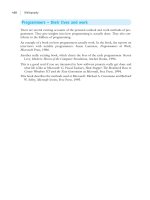
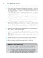
Figure 6.1. The time-line illustration of TCP connection management. (a) Three-way
handshake connection establishment; (b) Four-way handshake connection termination.
After this three-way handshake, a TCP connection is set up and data
transfer in both directions can begin. The TCP connection establishment
process is illustrated in Fig. 6.1(a).
6.3.2 TCP connection termination
A TCP connection is full-duplex, where each end application process can
transmit data to and receive data from the other end. During a TCP session,
it is possible that one end application has no more data to send, while the
other end does. Therefore, TCP adopts a four-way handshake to terminate
the connection, giving each end of the connection a chance to shut down
the one-way data flow. To do so, TCP sends a packet with the FIN flag set,
and the other end acknowledges the FIN segment. This process is called the
TCP Half-Close. After one of the data flows is shut down, the data flow in
the opposite direction still works. The TCP connection is terminated only
when the data flows of both directions are shut down. The TCP connection
termination process is illustrated in Fig. 6.1(b).
After the final ACK [segment (4) in Fig. 6.1(b)] is sent, the connection
must stay in the TIME WAIT state for twice the maximum segment life
(MSL)1 time before termination, just to make sure that all the data on this
connection has gone through. Otherwise, a delayed segment from an earlier
connection may be misinterpreted as part of a new connection that uses the
same local and remote sockets.
1
MSL is the maximum time that any segment can exist in the network before being discarded.
114
TCP study
If an unrecoverable error is detected, either end can close the TCP connection by sending a RST segment, where the Reset flag is set.
6.3.3 TCP timers
TCP uses a number of timers to manage the connection and the data flows.
r TCP Connection Establishment Timer. The maximum period of time
TCP keeps on trying to build a connection before it gives up.
r TCP Retransmission Timer. If no ACK is received for a TCP segment
when this timer expires, the segment will be retransmitted. We will discuss this timer in more detail in the next section.
r Delayed ACK Timer. Used for delayed ACK in TCP interactive data
flow, which we will discuss in Section 6.4.2.
r TCP Persist Timer. Used in TCP flow control in the case of a fast
transmitter and a slow receiver. When the advertised window size from
the receiver is zero, the sender will probe the receiver for its window size
when the TCP Persist Timer times out. This timer uses the normal TCP
Exponential Backoff algorithm, but with values bounded between 5 and
60 seconds.
r TCP Keepalive Timer. When a TCP connection has been idle for a long
time, a Keepalive timer reminds a station to check if the other end is still
alive.
r Two Maximum Segment Life Wait Timer. Used in TCP connection
termination. It is the period of time that a TCP connection keeps alive after
the last ACK packet of the four-way handshake is sent [see Fig.6.1(b)].
This gives TCP a chance to retransmit the final ACK.2 It also prevents the
delayed segments of a previous TCP connection from being interpreted
as segments of a new TCP connection using the same local and remote
sockets.
6.4 Managing the TCP data flow
To the application layer, TCP provides a byte-stream connection. The
sender TCP module receives a byte stream from the application, and puts
the bytes in a sending buffer. Then, TCP extracts the bytes from the sending
buffer and sends them to the lower network layer in blocks (called TCP
2
In Fig. 6.1(b), the server will timeout if the FIN segment is not acknowledged. It then retransmits the
FIN segment.
115
6.4 Managing the TCP data flow
segments). The receiver TCP module uses a receiving buffer to store and reorder received TCP segments. A byte stream is restored from the receiving
buffer and sent to the application process.
6.4.1 TCP error control
Since TCP uses the IP service, which is connectionless and unreliable,
TCP segments may be lost or arrive at the receiver in the wrong order. TCP
provides error control for application data, by retransmitting lost or errored
TCP segments.
Error detection
In order to detect lost TCP segments, each data byte is assigned a unique sequence number. TCP uses positive acknowledgements to inform the sender
of the last correctly received byte. Error detection is performed in each
layer of the TCP/IP stack (by means of header checksums), and errored
packets are dropped. If a TCP segment is dropped because TCP checksum
detects an error, an acknowledgement will be sent to the sender for the first
byte in this segment (also called the sequence number of this segment), thus
effectively only acknowledging the previous bytes with smaller sequence
numbers. Note that TCP does not have a negative acknowledgement feature.
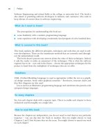
Furthermore, a gap in the received sequence numbers indicates a transmission loss or wrong order, and an acknowledgement for the first byte in the
gap may be sent to the sender. This is illustrated in Fig. 6.2. When segment
7 is received, the receiver returns an acknowledgement for segment 8 to
the sender. When segment 9 is lost, any received segment with a sequence
number larger than 9 (segments 10, 11, and 12 in the example) triggers a
time
segment 10 is received
segment 11 is received
segment 12 is received
Sender
...
segment 9 is lost
segment 8 is received
segment 7 is received
12 11 10
ack 9
ack 9
ack 9
8
7
...
Receiver
ack 8
ack 9
Figure 6.2. A received segment triggers the receiver to send an acknowledgement for the
next segment.
116
TCP study
duplicate acknowledgement for segment 9. When the sender receives such
duplicate acknowledgements, it will retransmit the requested segment (see
Section 6.4.3).
As the network link bandwidth increases, a window of TCP segments
may be sent and received before an acknowledgement is received by the
sender. If multiple segments in this window of segments are lost, the sender
has to retransmit the lost segments at a rate of one retransmission per
round trip time (RTT), resulting in a reduced throughput. To cope with
this problem, TCP allows the use of selective acknowledgement (SACK) to
report multiple lost segments. While a TCP connection is being established,
the two ends can use the TCP Sack-Permitted option to negotiate if SACK
is allowed. If both ends agree to use SACK, the receiver uses the TCP Sack
option to acknowledge all the segments that has been successfully received
in the last window of segments, and the sender can retransmit more than
one lost segment at a time.
RTT measurement and the retransmission timer
On the sender side, a retransmission timer is started for each TCP segment
sent. If no ACK is received when the timer expires (either the TCP packet
is lost, or the ACK is lost), the segment is retransmitted.
The value of the retransmission timer is critical to TCP performance.
An overly small value causes frequent timeouts and hence unnecessary
retransmissions, but a value that is too large causes a large delay when a
segment is lost. For best performance, the value should be larger than but
of the same order of magnitude as the RTT. Considering the fact that TCP
is used to connect different destinations with various RTTs, it is difficult
to set a fixed value for the retransmission timer. To solve this problem,
TCP continuously measures the RTT of the connection, and updates the
retransmission timer value dynamically.
Each TCP connection measures the time difference between sending
a segment and receiving the ACK for this segment. The measured delay
is called one RTT measurement, denoted by M. For a TCP connection,
there is at most one RTT measurement going on at any time instant. Since
the measurements may have wide fluctuations due to transient congestion
along the route, TCP uses a smoothed RTT, RT T s , and the smoothed
RTT mean deviation, RT T d , to compute the retransmission timeout (RTO)
value. RT T0s is set to the first measured RTT, M0 , while RT T0d = M0 /2
and RT O0 = RT T0s + max{G, 4 × RT T0d }. G is the timeout interval of
117
6.4 Managing the TCP data flow
base timer ticks
500ms
0
1
2
3
4
5
6
7
8
9
10
11
12
time
X
the real time out value
The timer starts here
with timeout value=6seconds
timer goes off
at the 12th tick
Figure 6.3. A TCP timer timeout example.
the base timer. For the ith measured RTT value Mi , RTO is updated as
follows (RFC 2988):
s
RT Tis = (1 − α) × RT Ti−1
+ α × Mi ,
RT Ti = (1 − β) ×
d
d
RT Ti−1
+ β × |Mi −
RT Oi = RT Ti + max{G, 4 × RT Ti },
s
d
(6.1)
s
RT Ti−1
|,
(6.2)
(6.3)
where α = 1/8 and β = 1/4. If the computed RTO is less than 1 second,
then it should be rounded up to 1 second, and a maximum value limit may
be placed on RTO provided that the maximum value is at least 60 seconds.
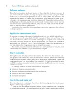
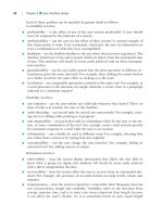
The TCP timers are discrete. In some systems, a base timer that goes off
every, e.g., 500 ms, is used for RTT measurements. If there are t base timer
ticks during a RTT measurement, the measured RTT is M = t × 500 ms.
Furthermore, all RTO timeouts occur at the base timer ticks. Figure 6.3
shows a timeout example when RT O = 6 seconds, and the timer goes off
at the 12th base timer tick after the timer is started. Clearly the actual time
out period is between 5.5 and 6 seconds. Different systems have different
clock granularities. Experience has shown that finer clock granularities
(e.g., G ≤ 100 ms) perform better than more coarse granularities [8].
RTO exponential backoff
RTT measurement is not performed for a retransmitted TCP segment in
order to avoid confusion, since it is not clear that if the received acknowledgement is for the original or the retransmitted segment. Both RT T s and
RT T d are not updated in this case. This is called Karn’s Algorithm.
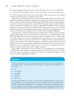
What if the retransmitted packet is also lost? TCP uses the Exponential
Backoff algorithm to update RTO when the retransmission timer expires for
a retransmitted segment. The initial RTO is measured using the algorithm
introduced above. Then, RTO is doubled for each retransmission, but with
a maximum value of 64 seconds (see Fig. 6.4).
118
TCP study
70
RTO (seconds)
60
50
40
30
20
10
0
0
2
4
6
8
Number of retransmissions
10
12
Figure 6.4. Exponential backoff of RTO after several retransmissions.
6.4.2 TCP interactive data flow
TCP supports interactive data flow, which is used by interactive user applications such as telnet and ssh. In these applications, a user keystroke is
first sent from the user to the server. Then, the server echoes the key back to
the user and piggybacks the acknowledgement for the key stroke. Finally,
the client sends an acknowledgement to the server for the received echo
segment, and displays the echoed key on the screen. This kind of design is
effective in reducing the delay experienced by the user, since a user would
prefer to see each keystroke displayed on the screen as quickly as possible,
as if he or she were using a local machine.
However, a better delay performance comes at the cost of bandwidth
efficiency. Consider one keystroke that generates one byte of data. The
total overhead of sending one byte of application data is 64 bytes (recall
that Ethernet has a minimum frame length of 64 bytes, including the TCP
header, the IP header, and the Ethernet header and trailer). Furthermore, for
each keystroke, three small packets are sent, resulting in a total overhead
of 64 × 3 = 192 bytes for only 2 bytes of data (one byte from the client to
the server, and one byte echoed from the server to the client). To be more
efficient, TCP uses two algorithms: Delayed Acknowledgement and the
Nagle algorithm, in order to reduce the number of small segments.
Delayed acknowledgement
TCP uses a delayed acknowledgement timer that goes off every K ms (e.g.,
50 ms). After receiving a data segment, TCP delays sending the ACK until
the next tick of the delayed acknowledgement timer, hoping that new data
to be sent in the reverse direction will arrive from the application during
119
6.4 Managing the TCP data flow
this period. If there is new data to send during this period, the ACK can
be piggybacked with the data segment. Otherwise, an ACK segment (with
no data payload) is sent. Depending on when the data segment is received,
when there is new data arriving from the application layer, and when the
delayed acknowledgement timer goes off, an ACK may be delayed from 0
ms up to K ms.
The Nagle algorithm
The Nagle Algorithm says that each TCP connection can have only one
small segment3 outstanding, i.e., that has not been acknowledged. It can
be used to further limit the number of small segments in the Internet. For
interactive data flows, TCP sends one byte and buffers all subsequent bytes
until an acknowledgement for the first byte is received. Then all buffered
bytes are sent in a single segment. This is more efficient than sending
multiple segments, each with one byte of data. But the higher bandwidth
efficiency comes at the cost of increased delay for the user.
6.4.3 TCP bulk data flow
In addition to interactive flows, TCP also supports bulk data flows, where
a large number of bytes are sent through the TCP connection. Applications
using this type of service include email, FTP, WWW, and many others.
TCP throughput performance is an important issue related to the TCP
bulk data flows. Ideally, a source may wish to always use the maximum
sending rate, in order to deliver the application bulk data as quickly as
possible. However, as discussed in Section 0.8, if there is congestion at
an intermediate router or at the receiving node, the more packets a source
sends, the more packets would be dropped. Furthermore, the congestion
will persist until some or all of the data flows reduce their transmission rates.
Therefore, for a high throughput, the source should always try to increase
its sending rate. On the other hand, for a low packet loss rate, the source
rate should be bounded by the maximum rate that can be allowed without
causing congestion or receiver buffer overflow, and should be adaptive to
network conditions.
TCP sliding window flow control
TCP uses sliding window flow control to avoid receiver buffer overflow,
where the receiver advertises the maximum amount of data it can receive
3
which is less than one MSS.
120
TCP study
advertised window
Wl
1
2
3
4
5
6
sent but
not acked
sent and acked
7
Wm
8
can be
sent
9
Wr
10
11
cannot be sent as yet
(a)
1
2
3
4
5
6
7
8
9
10
11
(b)
Figure 6.5. A TCP sliding window flow control example. (a) The sliding window
maintained by the sender. (b) The updated sliding window when an acknowledgement,
[ackno = 5, awnd = 6] is received.
(called the Advertised Window, or awnd), and the sender is not allowed to
send more data than the advertised window.
Figure 6.5(a) illustrates the sliding window flow control algorithm. The
application data is a stream of bytes, where each byte has a unique sequence
number. In Fig. 6.5, each block represents a TCP segment with MSS bytes,
and the number can be regarded as the sequence number of the TCP segments in units of MSS bytes. In TCP, the receiver notifies the sender (1) the
next segment it expects to receive and (2) the amount of data it can receive
without causing a buffer overflow (denoted as [ackno = x, awnd = y]),
using the Acknowledgement Number and the Window Size fields in the
TCP header. Figure 6.5(a) is the sliding window maintained at the sender.
In this example, segments 1 through 3 have been sent and acknowledged.
Since the advertised window is five segments and the sender already has
three outstanding segments (segments 4, 5, and 6), at most two more segments can be sent before a new acknowledgement is received.
The sliding window, shown as a box in Fig. 6.5, moves to the right as
new segments are sent, or new acknowledgements and window advertisements are received. More specifically, if a new segment is acknowledged,
Wl , the left edge of the window, will move to the right (window closes).
Wm moves to the right when new segments are sent. If a larger window
is advertised by the receiver or when new segments are acknowledged,
the right edge of the sliding window, Wr , will move to the right (window
opens). However, if a smaller window is advertised, Wr will move to the
left (window shrinks). Figure 6.5(b) illustrates the updated sliding window
when an acknowledgement, [ackno = 5, awnd = 6], is received.
With this technique, the sender rate is effectively determined by (1)
the advertised window, and (2) how quickly a segment is acknowledged.
Thus a slow receiver can advertise a small window or delay the sending of
121
6.4 Managing the TCP data flow
acknowledgements to slow down a fast sender, in order to keep the receiver
buffer from overflowing. However, even with effective flow control, a TCP
segment may still be dropped at an intermediate router when the router
buffer is full due to congestion. In addition to sliding window flow control,
TCP uses congestion control to cope with network congestion.
TCP congestion control
TCP uses congestion control to adapt to network congestion and achieve
a high throughput. Usually the buffer in a router is shared by many TCP
connections and other non-TCP data flows, since a shared buffer leads to a
more efficient buffer utilization and is easier to implement than assigning
a separate buffer for each flow. TCP needs to adjust its sending rate in
reaction to the rate fluctuations of other data flows sharing the same router
buffer. In other words, a new TCP connection should increase its rate as
quickly as possible to take all the available bandwidth. When the sending
rate is higher than some threshold, TCP should slow down its rate increase
to avoid congestion.
Considering the huge number of TCP connections going through an Internet core router, routers are designed to be as simple as possible. Usually
a router simply drops incoming packets when its buffer is full, without notifying the sender. However, the sender can infer congestion along the route
when a retransmission timer goes off. In addition, the receiver also reports
congestion to the sender implicitly by sending duplicate acknowledgements
(see Fig. 6.2). When congestion occurs, TCP drastically reduces its sending
rate. The reason is that if the router is congested, the more data sent, the
more data would be dropped. Furthermore, if some of the TCP connections
lose packets and reduce their rates, it is likely that the congestion will abate
and disappear.
More specifically, the sender maintains two variables for congestion
control: a congestion window size (cwnd), which upper bounds the sender
rate, and a slow start threshold (ssthr esh), which determines how the
sender rate is increased. The TCP slow start and congestion avoidance
algorithms are given in Table 6.1. According to these algorithms, cwnd
initially increases exponentially until it reaches ssthr esh. After that, cwnd
increases roughly linearly. When congestion occurs, cwnd is reduced to
1 MSS to avoid segment loss and to alleviate congestion. It has been shown
that when N TCP connections with similar RTTs share a bottleneck router
with an output link bandwidth of C, their long-term average rates quickly
converge to the optimal operating rates, i.e., each TCP connection has an
TCP study
Table 6.1. The slow start and congestion avoidance algorithms
(1)
If cwnd ≤ ssthr esh then
/* Slow Start Phase */
Each time an ACK is received:
cwnd = cwnd + segsi ze
else /* Congestion Avoidance Phase */
Each time an ACK is received:
cwnd = cwnd + segsi ze × segsi ze/cwnd + segsi ze/8
end
(2)
When congestion occurs (indicated by retransmission timeout)
ssthr esh = max(2, min(cwnd, awnd)/2)
cwnd = 1 segsi ze = 1 M SS bytes
(3)
Allowed window = min(cwnd, awnd)
1e+05
cwnd
ssthresh
1e+05
1e+05
Bytes
122
8e+04
6e+04
4e+04
2e+04
0e+00
0
100
200
300
400
500
600
700
800
900 1000
Time (RTT)
Figure 6.6. The evolution of cwnd and ssthr esh for a TCP connection, including slow
start, congestion avoidance, fast retransmit, and fast recovery.
average rate of C/N , when this additive-increase-multiplicative-decrease
(AIMD) algorithm is used [9]. Another advantage of this algorithm is that
it is self-clocking. The higher the rate at which acknowledgements are
received (which implies that the congestion is light), the quicker the sending
rate increases. Figure 6.6 illustrates the evolution of cwnd and ssthr esh
of a TCP connection. It can be seen clearly that the evolution of cwnd has
two phases, i.e., an exponential increase phase and a linear increase phase.
When there is a packet loss, cwnd drops drastically.
TCP allows accelerated retransmissions. Recall that when there is a gap
in the receiving buffer, the receiver will acknowledge the first byte in the
123
6.5 Tuning the TCP/IP kernel
Table 6.2. TCP fast retransmit/fast recovery algorithm
(1)
After the third duplicate ACK is received:
ssthr esh = cwnd/2
retransmit the missing segment
cwnd = ssthr esh + 3segsi ze
(2)
For each additional duplicate acknowledgement received:
cwnd = cwnd + segsi ze
transmit a segment if allowed by cwnd
(3)
When the acknowledgement for the retransmitted segment arrives:
cwnd = ssthr esh + segsi ze
gap. Further arriving segments, other than the segment corresponding to the
gap, trigger duplicate acknowledgements (see Figure 6.2). After receiving
three duplicate acknowledgements, the sender assumes that the segment
is lost and retransmit the segment immediately without waiting for the
retransmission timer to expire. This algorithm is called the fast retransmit
algorithm. After the retransmission, congestion avoidance, rather than slow
start, is performed, with an initial cwnd equal to ssthr esh plus one segment
size.4 This is called the fast recovery algorithm. With these two algorithms,
cwnd and ssthr esh are updated as shown in Table 6.2. In the example
shown in Fig. 6.6, TCP fast retransmit and fast recovery occur at time
instances around 610, 740, and 950.
6.5 Tuning the TCP/IP kernel
TCP/IP uses a number of parameters in its operations (e.g., TCP keepalive
timer). Since the TCP/IP protocols are used in many applications, a set of
default values may not be optimal for different situations. In addition, the
network administrator may wish to turn on (or off) some TCP/IP functions
(e.g., ICMP redirect) for performance or security considerations. Many
Unix and Linux systems provide some flexibity in tuning the TCP/IP kernel.
In Red Hat Linux, /sbin/sysctl is used to configure the Linux
kernel parameters at runtime. The default kernel configuration file is
/sbin/sysctl.conf, consisting of a list of kernel parameters and their
4
The duplicate acknowledgements imply that the subsequent segments have been received. Therefore,
the network is not congested and the sender need not switch to the slow start phase to reduce its rate.
124
TCP study
default values. For the parameters with binary values, a “0” means the function is disabled, while a “1” means the function is enabled. Some frequently
used sysctl options are listed here.
r sysctl -a or sysctl -A: list all current values.
r sysctl -p file name: to load the sysctl setting from a configuration file. If
no file name is given, /etc/sysctl.conf is used.
r sysctl -w variable=value: change the value of the parameter.
The TCP/IP related kernel parameters are stored in the
/proc/sys/net/ipv4/ directory. As an alternative to the sysctl
command, you can modify these files directly to change the TCP/IP kernel
setting. For example, the default value of the TCP keepalive timer is saved
in the /proc/sys/net/ipv4/tcp keepalive time file. As root, you
can run
echo ’3600’ > /proc/sys/net/ipv4/tcp keepalive time
to change the TCP keepalive timer value from its default 7200 seconds to
3600 seconds.
Solaris 8.0 provides a program, ndd, for tuning the TCP/IP kernel, including
the IP, ICMP, ARP, UDP and TCP modules. To display a list of parameters
editable in a module, use the following command:
ndd module \?,
where module could be /dev/ip, /dev/icmp, /dev/arp, /dev/udp, or
/dev/tcp. To display the current value of a parameter, use:
ndd -get module parameter.
To modify the value of a parameter in a module, use:
ndd -set module parameter.
6.6 TCP diagnostic tools
6.6.1 The distributed benchmark system
The distributed benchmark system (DBS) is a benchmark for TCP performance evaluation. It can be used to run tests with multiple TCP connections
or UDP flows and to plot the test results. DBS consists of three tools.
r dbsc: the DBS test controller.
125
6.6 TCP diagnostic tools
(1)
DBS hosts
DBS hosts
(2)
(1)
Controller
(3)
(3)
(3) ...
(3)
(1)
...
(2)
(1)
Figure 6.7. The operation of DBS.
r dbsd: the DBS daemon, running on each participating host.
r dbs view: a Perl script file, used to plot the experiment results.
DBS uses a command file to describe the test setting. In the command
file, a user can specify (1) how many TCP or UDP flows to generate, (2)
the sender and receiver for each flow, (3) the traffic pattern and duration of
each flow, and (4) which statistics to collect. During a test, one host serves
as the controller, running dbsc, and all other participating hosts are DBS
hosts, running dbsd. As illustrated in Fig. 6.7, the controller first reads the
command file and sends instructions to all the DBS hosts. Second, TCP (or
UDP) connections will be set up between the DBS hosts and TCP (or UDP)
traffic is transmitted on these connections as specified in the command file.
Third, when the data transmissions are over, the DBS controller collects
statistics from the DBS hosts which may be plotted using dbs view.
6.6.2 NIST Net
NIST Net is a Linux-based network emulator. It can be used to emulate various network conditions, such as packet loss, duplication, delay and jitter,
bandwidth limitations, and network congestion. As illustrated in Fig. 6.8, a
Linux host running NIST Net serves as a router between two subnets. There
are a number of TCP connections or UDP flows traversing this router host.
NIST Net works like a firewall. A user can specify a connection, by indicating its source IP and destination IP, and enforce a policy, such as a certain
delay distribution, a loss distribution, or introduce packet duplication on
this connection.
126
TCP study
TCP connection 1
Host R
...
...
TCP connection 2
Figure 6.8. The operation of NIST Net.
6.6.3 Tcpdump output of TCP packets
Generally, tcpdump outputs a captured TCP packet in the following
format.
timestamp
src IP.src port > dest IP.dest port: flags seq no ack window urgent options
The following is a sample tcpdump output, which shows a TCP packet
captured at time 54:16.401963 (Minute:Second:MicroSecond). The TCP
connection is between aida.poly.edu and mng.poly.edu, with source
TCP port 1121 and destination TCP port telnet (23). The PUSH flag
bit is set. The sequence number of the first data byte is 1,031,880,194,
and 24 bytes of data is carried in this TCP segment. aida is expecting byte 172,488,587 from mng and advertises a window size of 17,520
bytes.
54:16.401963
aida.poly.edu.1121 > mng.poly.edu.telnet: P 1031880194
:1031880218(24) ack 172488587 win 17520
6.7 Exercises on TCP connection control
Exercise 1
While tcpdump -S host your host and remote host is running, execute: telnet
remote host time.
Save the tcpdump output.
Explain TCP connection establishment and termination using the
tcpdump output.
LAB REPORT
LAB REPORT
What were the announced MSS values for the two hosts?
127
6.8 Exercise on TCP interactive data flow
What happens if there is an intermediate network that has an MTU less
than the MSS of each host?
See if the DF flag was set in our tcpdump output.
Exercise 2 While tcpdump -nx host your host and remote host is running, use sock to send
a UDP datagram to the remote host:
sock -u -i -n1 remote host 8888.
Save the tcpdump output for your lab report.
Restart the above tcpdump command, execute sock in the TCP mode:
sock -i -n1 remote host 8888.
Save the tcpdump output for your lab report.
Explain what happened in both the UDP and TCP cases. When a client
requests a nonexisting server, how do UDP and TCP handle this request,
respectively?
LAB REPORT
6.8 Exercise on TCP interactive data flow
Exercise 3 While tcpdump is capturing the traffic between your machine and a remote machine,
issue the command: telnet remote host.
After logging in to the host, type date and press the Enter key.
Now, in order to generate data faster than the round-trip time of a single byte to be
sent and echoed, type any sequence of keys in the telnet window very rapidly.
Save the tcpdump output for your lab report. To avoid getting unwanted lines from
tcpdump, you and the student who is using the remote machine should do this
experiment in turn.
Answer the following questions, based upon the tcpdump output saved
in the above exercise.
(1) What is a delayed acknowledgement? What is it used for?
(2) Can you see any delayed acknowledgements in your tcpdump output?
LAB REPORT
If yes, explain the reason. Mark some of the lines with delayed acknowledgements, and submit the tcpdump output with your report.
Explain how the delayed ACK timer operates from your tcpdump
output.
If you don’t see any delayed acknowledgements, explain the reason
why none was observed.
128
TCP study
(3) What is the Nagle algorithm used for?
From your tcpdump output, can you tell whether the Nagle algorithm
is enabled or not? Give the reason for your answer.
From your tcpdump output for when you typed very rapidly, can you
see any segment that contains more than one character going from your
workstation to the remote machine?
6.9 Exercise on TCP bulk data flow
Exercise 4 While tcpdump is running and capturing the packets between your machine and
a remote machine, on the remote machine, which acts as the server, execute:
sock -i -s 7777.
Then, on your machine, which acts as the client, execute:
sock -i -n16 remote host 7777.
Do the same experiment three times. Save all the tcpdump outputs for your lab
report.
Using one of three tcpdump outputs, explain the operation of TCP in
terms of data segments and their acknowledgements. Does the number of
data segments differ from that of their acknowledgements?
LAB REPORT
Compare all the tcpdump outputs you saved. Discuss any differences
among them, in terms of data segments and their acknowledgements.
From the tcpdump output, how many different TCP flags can you see?
Enumerate the flags and explain their meanings.
LAB REPORT
How many different TCP options can you see? Explain their meanings.
6.10 Exercises on TCP timers and retransmission
Exercise 5 Execute sysctl -A | grep keepalive to display the default values of the TCP kernel
parameters that are related to the TCP keepalive timer.
What is the default value of the TCP keepalive timer? What is the maximum number
of TCP keepalive probes a host can send?
In Solaris, execute ndd -get /dev/tcp tcp keepalive interval to display the
default value of the TCP keepalive timer.
129
6.11 Other exercises
LAB REPORT
Answer the above questions.
Exercise 6 While tcpdump is running to capture the packets between your host and a remote
host, start a sock server on the remote host, sock -s 8888.
Then, execute the following command on your host,
sock -i -n200 remote host 8888.
While the sender is injecting data segments into the network, disconnect the cable
connecting the sender to the hub for about ten seconds.
After observing several retransmissions, reconnect the cable. When all the data
segments are sent, save the tcpdump output for the lab report.
LAB REPORT
Submit the tcpdump output saved in this exercise.
From the tcpdump output, identify when the cable was disconnected.
Describe how the retransmission timer changes after sending each retransmitted packet, during the period when the cable was disconnected.
Explain how the number of data segments that the sender transmits at once
(before getting an ACK) changes after the connection is reestablished.
6.11 Other exercises
Exercise 7
While tcpdump src host your host is running, execute the following command,
which is similar to the command we used to find out the maximum size of a UDP
datagram in Chapter 5,
sock -i -n1 -wn host echo
Let n be larger than the maximum UDP datagram size we found in Exercise 5 of
Chapter 5. As an example, you may use n = 70,080.
LAB REPORT
Did you observe any IP fragmentation?
If IP fragmentation did not occur this time, how do you explain this compared to what you observed in Exercise 5 of Chapter 5?
Exercise 8 Study the manual page of /sbin/sysctl. Examine the default values of some TCP/IP
configuration parameters that you might be interested in. Examing the configuration
files in the /proc/sys/net/ipv4 directory.
When Solaris is used, use ndd to examine the TCP/IP configuration parameters. See Section 6.5 or the manual page of ndd for the syntax and
parameters.
130
TCP study
Table 6.3. Two groups for exercises in Section 6.12
-
host1
host2
host3
host4
Group A
Group B
shakti
yachi
vayu
fenchi
agni
guchi
apah
kenchi
6.12 Exercises with DBS and NIST Net
In this exercise, students are divided into two groups as shown in Table 6.3.
The four hosts in each group are connected by a hub. All the hosts have the
default IP addresses and subnet masks as shown in Table 1.2.
Before these exercises, the lab instructor should start ntpd to synchronize
the hosts. First, modify the /etc/ntp.conf file in all the hosts as follows:
(1) comment the “restrict default ignore” line, and (2) for host1, host2, and
host3 in Group A, insert a new line “server 128.238.66.103”; for host1,
host2, and host3 in Group B, insert a new line “server 128.238.66.107”. For
example, the /etc/ntp.conf file in host1, host2, and host3 look should
like the following:
···
# restrict default ignore
···
server 128.238.66.103 # for Group A
# server 128.238.66.107 # for Group B
···
Second, start the ntpd daemon by running /etc/init.d/ntpd start. Then all
the hosts in Group A (Group B) will be synchronized with apah (kenchi).
Note that it may take a while (several minutes) for the hosts to be synchronized, since by default an NTP client polls a server every 60 seconds.
Exercise 9
In the following, we will use DBS to study the performance of TCP under different background traffic. The DBS command files used in this exercise are given in
Appendix C.1.
The TCP1.cmd file in Section C.1.1 of Appendix C1 is used to set up a TCP connection
between host1 and host2, where host2 sends a stream of packets to host1. Edit
the TCP1.cmd file, replace the values for the hostname variable to the IP addresses
131
6.12 Exercises with DBS and NIST Net
of the corresponding hosts in your group as shown in Table 6.3. For example, in
group A, host1 is shakti and host2 is vayu. So the TCP1.cmd for Group A should
be changed as shown below:
···
sender {
hostname = 128.238.66.101
···
receiver {
hostname = 128.238.66.100
···
In all the following experiments, we will use host4 as the DBS controller. Start
tcpdump host host1 IP and host2 IP on all the hosts. Then start dbsd on all other
hosts except host4 (apah in Group A and kenchi in Group B). Next, execute dbsc
TCP1.cmd on host4.
Observe the data transmissions between host1 and host2 from the tcpdump
output.
When the data transmission is over, execute the following two commands on host4
to plot the received sequence numbers and throughput of the TCP connection:
dbs view -f TCP1.cmd -sq sr -p -ps -color > ex9sqa.ps,
dbs view -f TCP1.cmd -th r -p -ps -color > ex9tha.ps.
Save these two Postscript files for the lab report. You can use the GIMP graphical
tool in Red Hat Linux to convert the Postscript files to other formats. The second
dbs view command also gives the average throughput of the TCP connection. Save
this number for the lab report.
Next, edit the TCPUDP.cmd file given in Section C.1.2 of Appendix C. Replace
the hostname fields with the corresponding IP addresses for the senders and
the receivers according to Table 6.3. Then, repeat the above exercise, but use the
TCPUDP.cmd file. This file consists of commands to start a TCP connection with
the same parameters as the previous exercise, and a UDP flow emulating an MPEG
video download. Oberve the impact on TCP performance of the UDP flow.
When the data transmission is over, execute the following two commands to plot
the received sequence numbers and throughput of the TCP connection:
dbs view -f TCPUDP.cmd -sq sr -p -ps -color > ex9sqb.ps,
dbs view -f TCPUDP.cmd -th r -p -ps -color > ex9thb.ps.
Save these two Postscript files, as well as the average throughputs of the TCP
connection and the UDP flow.
132
TCP study
Table 6.4. The NIST Net settings for Exercise 10
Source
Dest
Delay (ms)
host1 IP
host3 IP
host2 IP
host2 IP
20 ms
500 ms
Compare the throughput of the TCP connections in the above two experiments. In which case does the TCP connection have higher throughput?
Justify you answer with the throughput plots and the sequence number
plots.
LAB REPORT
Exercise 10 5 In one command window, execute tcpdump ip host host1 IP and host2 IP to
capture the TCP packets between host1 and host2. In another command window,
run tcpdump ip host host3 IP and host2 IP to capture the TCP packets between
host3 and host2.
On host1, execute Load.Nistnet to load the NIST Net emulator module into the Linux
kernel.
Execute xnistnet on host1 (shakti in Group A and yachi in Group B). Enter the
values in the NIST Net GUI as given in Table 6.4. Then click the Update button
to enforce a 20 ms delay on the TCP connection between host1 and host2, and a
500 ms delay on the TCP connection between host2 and host3.
Start the DBS daemon on host1, host2, and host3, by running dbsd -d.
Edit the TCP2.cmd file given in Section C.1.3 of Appendix C on host4. Set the
hostname values in the command file to the corresponding IP addresses according
to Table 6.3. Execute the DBS controller on host4, by dbsc TCP2.cmd.
Observe the data transmissions shown in the tcpdump outputs. When data transmissions are over, save the tcpdump outputs and use the following command to
plot the received sequence numbers and throughputs of the two TCP connections:
dbs view -f TCP2.cmd -sq sr -p -ps -color > ex10sq.ps,
dbs view -f TCP2.cmd -th r -p -ps -color > ex10th.ps,
Save the plots and the mean throughputs of the two TCP connections from the
dbs view outputs.
From the received sequence number plot, can you tell which TCP
connection has higher throughput? Why? Justify your answer using the
tcpdump outputs and the dbs view plots.
LAB REPORT
5
This exercise is for Linux only, since NIST Net does not run on Solaris.
133
6.12 Exercises with DBS and NIST Net
Exercise 11 6 Restart the xnistnet program on host1. Set Source to host2’s IP address
and Dest to host1’s IP address. Set Delay for this connection to be 500 ms, and
Delsigma to 300 ms. This enforces a mean delay of 500 ms and a delay deviation
of 300 ms for the IP datagrams between host1 and host2.
Execute tcpdump ip host host1 IP and host2 IP on all the hosts.
Start a sock server on host1 by running sock -i -s 7777. Start a sock client on
host2 by running sock -i -n50 host1 IP 7777 to pump TCP packets to host1.
When the data transfer is over, examine the tcpdump outputs to see if a retransmission or fast retransmission occured. If you cannot see one, you may try running the
sock program again.
Submit the section of a tcpdump output saved that has out of order TCP
segments arriving at the receiver.
LAB REPORT
Exercise 12 7 This exercise is similar to the previous one, except that Delay is set to 100 ms,
Delsigma is set to 0 ms, and Drop is set to 5%.
Run the sock server and client. When the data transfer is over, examine the tcpdump
output. Can you see any packet loss and retransmission? Justify your answer using
the tcpdump output.
Try different values for the Drop field, or different combinations of Delay,
DelSigma, and Drop.
LAB REPORT
6
7
Answer the above questions.
This exercise is for Linux only, since NIST Net does not support Solaris.
This exercise is for Linux only, since NIST Net does not support Solaris.
7
Multicast and realtime service
We are now in a transition phase, just a few years shy of when IP will be the
H. Schulzrinne
universal platform for multimedia services.
7.1 Objectives
r
r
r
r
r
r
Multicast addressing.
Multicast group management.
Multicast routing: configuring a multicast router.
Realtime video streaming using the Java Media Framework.
Protocols supporting realtime streaming: RTP/RTCP and RTSP.
Analyzing captured RTP/RTCP packets using Ethereal.
7.2 IP multicast
IP provides three types of services, i.e., unicast, multicast, and broadcast.
Unicast is a point-to-point type of service with one sender and one receiver.
Multicast is a one-to-many or many-to-many type of service, which delivers
packets to multiple receivers. Consider a multicast group consisting of a
number of participants, any packet sent to the group will be received by all
of the participants. In broadcasts, IP datagrams are sent to a broadcast IP
address, and are received by all of the hosts.
Figure 7.1 illustrates the differences between multicast and unicast. As
shown in Fig. 7.1(a), if a node A wants to send a packet to nodes B, C,
and D using unicast service, it sends three copies of the same packet,
each with a different destination IP address. Then, each copy of the packet
will follow a possibly different path from the other copies. To provide
a teleconferencing-type service for a group of N nodes, there need to be
134
135
7.2 IP multicast
(b)
(a)
Network
A
Network
B
C
A
D
B
C
D
Figure 7.1. Comparison of IP unicast and multicast. (a) A unicast example, where node A
sends three copies of the same packet to nodes B, C, and D. (b) A multicast example,
where node A sends a packet to the multicast group, which consists of nodes B, C,
and D.
N (N − 1)/2 point-to-point paths to provide a full connection. On the other
hand, if multicast service is used, as illustrated in Fig. 7.1(b), node A only
needs to send one copy of the packet to a common group address.1 This
packet will be forwarded or replicated in a multicast tree where node A is
the root and nodes B, C, D are the leaves. All nodes in this group, including
node B, C, and D, will receive this packet. With multicast, clearly less
network resources are used.
IP multicast is useful in providing many network services, e.g., naming (DNS), routing (RIP-2), and network management (SNMP). In many
cases, it is used when a specific destination IP address is unknown. For
example, in the ICMP router discovery exercise in Chapter 4, a host sends
an ICMP router solicitation message to a multicast group address meaning
all routers in this subnet. All routers connecting to this subnet receive this request, although the host may not know if there are any routers
out there, and if there are, what IP addresses their interfaces have. In addition, IP multicast is widely used in multimedia streaming (e.g., video
conferencing and interactive games) due to its efficiency. As illustrated
in Fig. 7.1, a multicast group (consisting of nodes A, B, C, D) is easier
to manage and uses less network resources than providing an end-to-end
connection between every two participating nodes.
The example in Fig. 7.1(b) illustrates the three key components in providing multicast services.
1
RFC 1112 indicates that the sender, e.g. node A, does not have to be in the multicast group.