Ebook Modern control systems (11th edition) Part 2
Bạn đang xem bản rút gọn của tài liệu. Xem và tải ngay bản đầy đủ của tài liệu tại đây (21.52 MB, 260 trang )
9
Oscillators
This chapter describes circuits that generate sine
wave, square wave, and triangular waveforms.
These oscillator circuits form the basis of clocks
and timing arrangements as well as signal and
function generators.
Vin ' = Vin + 0Vout
Positive feedback
and
In Chapter 7, we showed how negative feedback
can be applied to an amplifier to form the basis of a
stage which has a precisely controlled gain. An
alternative form of feedback, where the output is
fed back in such a way as to reinforce the input
(rather than to subtract from it), is known as
positive feedback.
Figure 9.1 shows the block diagram of an
amplifier stage with positive feedback applied.
Note that the amplifier provides a phase shift of
180° and the feedback network provides a further
180°. Thus the overall phase shift is 0°. The overall
voltage gain, G, is given by:
Overall gain, G =
Vout
V in
Figure 9.1 Amplifier with positive feedback applied
By applying Kirchhoff’s Voltage Law
thus
Vin = Vin ' 0Vout
Vout = Av × Vin
where Av is the internal gain of the amplifier.
Hence:
Overall gain, G =
Thus, G =
Av × Vin '
Av × Vin '
=
Vin ' 0Vout Vin ' 0 ( Av × Vin ')
Av
1 0Av
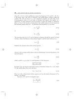
Now consider what will happen when the loop
gain, 0Av, approaches unity (i.e., when the loop
gain is just less than 1). The denominator (1 2 0Av)
will become close to zero. This will have the effect
of increasing the overall gain, i.e. the overall gain
with positive feedback applied will be greater than
the gain without feedback.
172
ELECTRONIC CIRCUITS: FUNDAMENTALS AND APPLICATIONS
It is worth illustrating this difficult concept using
some practical figures. Assume that you have an
amplifier with a gain of 9 and one-tenth of the
output is fed back to the input (i.e. 0 = 0.1). In this
case the loop gain (0 × Av) is 0.9.
With negative feedback applied (see Chapter 7)
the overall voltage gain will be:
Av
9
9
9
=
=
=
= 4.7
1 + 0 Av 1 + ( 0.1 × 9 ) 1 + 0.9 1.9
G=
With positive feedback applied the overall voltage
gain will be:
G=
Av
=
1 0 Av 1
10
10
10
=
=
= 90
0.1
×
9
1
0.9
0.1
(
)
Now assume that you have an amplifier with a gain
of 10 and, once again, one-tenth of the output is fed
back to the input (i.e. 0 = 0.1). In this example the
loop gain (0 × Av) is exactly 1.
With negative feedback applied (see Chapter 7)
the overall voltage gain will be:
G=
Av
10
10 10
=
=
= =5
1 + 0Av 1 + ( 0.1×10) 1 + 1 2
With positive feedback applied the overall voltage
gain will be:
Av
=
G=
1 0Av 1
10
10 10
=
=
=
0.1
10
1
1 0
×
(
)
This simple example shows that a loop gain of
unity (or larger) will result in infinite gain and an
amplifier which is unstable. In fact, the amplifier
will oscillate since any disturbance will be
amplified and result in an output.
Clearly, as far as an amplifier is concerned,
positive feedback may have an undesirable effect—
instead of reducing the overall gain the effect is
that of reinforcing any signal present and the output
can build up into continuous oscillation if the loop
gain is 1 or greater. To put this another way,
oscillator circuits can simply be thought of as
amplifiers that generate an output signal without
the need for an input!
Conditions for oscillation
From the foregoing we can deduce that the
conditions for oscillation are:
(a) the feedback must be positive (i.e. the signal
fed back must arrive back in-phase with the signal
at the input);
(b) the overall loop voltage gain must be greater
than 1 (i.e. the amplifier’s gain must be sufficient
to overcome the losses associated with any
frequency selective feedback network).
Hence, to create an oscillator we simply need an
amplifier with sufficient gain to overcome the
losses of the network that provide positive
feedback. Assuming that the amplifier provides
180° phase shift, the frequency of oscillation will
be that at which there is 180° phase shift in the
feedback network.
A number of circuits can be used to provide 180°
phase shift, one of the simplest being a three-stage
C–R ladder network that we shall meet next.
Alternatively, if the amplifier produces 0° phase
shift, the circuit will oscillate at the frequency at
which the feedback network produces 0° phase
shift. In both cases, the essential point is that the
feedback should be positive so that the output
signal arrives back at the input in such a sense as to
reinforce the original signal.
Ladder network oscillator
A simple phase-shift oscillator based on a threestage C–R ladder network is shown in Fig. 9.2.
TR1 operates as a conventional common-emitter
amplifier stage with R1 and R2 providing base bias
potential and R3 and C1 providing emitter
stabilization.
The total phase shift provided by the C–R ladder
network (connected between collector and base) is
180° at the frequency of oscillation. The transistor
provides the other 180° phase shift in order to
realize an overall phase shift of 360° or 0° (note
that these are the same).
The frequency of oscillation of the circuit shown
in Fig. 9.2 is given by:
f =
1
2K × 6CR
The loss associated with the ladder network is 29,
thus the amplifier must provide a gain of at least 29
in order for the circuit to oscillate. In practice this
is easily achieved with a single transistor.
OSCILLATORS
Figure 9.2 Sine wave oscillator based on a threestage C–R ladder network
Example 9.1
Determine the frequency of oscillation of a threestage ladder network oscillator in which
C = 10 nF and R = 10 kL.
Solution
Using
f =
2K × 6CR
gives
f=
Figure 9.3 A Wien bridge network
signals will be in-phase). If we connect the network
to an amplifier producing 0° phase shift which has
sufficient gain to overcome the losses of the Wien
bridge, oscillation will result.
The minimum amplifier gain required to sustain
oscillation is given by:
Av = 1 +
1
1
6.28× 2.45×10×10 9 ×10 ×103
1
104
=
= 647 Hz
4
6.28 × 2.45 ×10
15.386
f =
An alternative approach to providing the phase
shift required is the use of a Wien bridge network
(Fig. 9.3). Like the C–R ladder, this network
provides a phase shift which varies with frequency.
The input signal is applied to A and B while the
output is taken from C and D. At one particular
frequency, the phase shift produced by the network
will be exactly zero (i.e. the input and output
1
2 K × C1C 2 R1 R 2
When Rl = R2 and Cl = C2 the frequency at which
the phase shift will be zero will be given by:
f =
Wien bridge oscillator
C1 R2
+
C 2 R1
In most cases, C1 = C2 and R1 = R2, hence the
minimum amplifier gain will be 3.
The frequency at which the phase shift will be
zero is given by:
from which
f =
173
1
2K × C R
2
2
=
1
2KCR
where R = Rl = R2 and C = Cl = C2.
Example 9.2
Figure 9.4 shows the circuit of a Wien bridge
oscillator based on an operational amplifier. If Cl =
C2 = 100 nF, determine the output frequencies
produced by this arrangement (a) when Rl = R2 =
1 kL and (b) when Rl = R2 = 6 kL.
174
ELECTRONIC CIRCUITS: FUNDAMENTALS AND APPLICATIONS
Multivibrators
There are many occasions when we require a
square wave output from an oscillator rather than a
sine wave output. Multivibrators are a family of
oscillator circuits that produce output waveforms
consisting of one or more rectangular pulses. The
term ‘multivibrator’ simply originates from the fact
that this type of waveform is rich in harmonics (i.e.
‘multiple vibrations’).
Multivibrators use regenerative (i.e. positive)
feedback; the active devices present within the
oscillator circuit being operated as switches, being
alternately cut off and driven into saturation.
The principal types of multivibrator are:
Figure 9.4 Sine wave oscillator based on a Wien
bridge network (see Example 9.2)
(a) astable multivibrators that provide a
continuous train of pulses (these are sometimes
also referred to as free-running multivibrators)
Solution
(b) monostable multivibrators that produce a
single output pulse (they have one stable state and
are thus sometimes also referred to as ‘one-shot’)
(a)
When R1 = R2 = 1 kL
f =
1
2K CR
(c) bistable multivibrators that have two stable
states and require a trigger pulse or control signal
to change from one state to another.
where R = R1 = R1 and C = C1 = C2.
Thus
(b)
f =
1
6.28 × 100 × 10 9 × 1× 103
f =
104
= 1.59 kHz
6.28
When R1 = R1 = 6 kL
f =
1
2K CR
where R = R1 = R1 and C = C1 = C2.
Thus
f=
1
6.28×100 ×10 9 × 6 ×103
f =
10 4
= 265 Hz
37.68
Figure 9.5 This high-speed bistable multivibrator
uses two general-purpose silicon transistors and
works at frequencies of up to 1 MHz triggered from
an external signal
OSCILLATORS
175
Figure 9.6 Astable multivibrator using BJTs
Figure 9.8 Waveforms for the BJT multivibrator
shown in Fig. 9.6
Figure 9.7 Circuit of Fig. 9.6 redrawn to show
two common-emitter amplifier stages with positive
feedback
The astable multivibrator
Figure 9.6 shows a classic form of astable
multivibrator based on two transistors. Figure 9.7
shows how this circuit can be redrawn in an
arrangement that more closely resembles a twostage common-emitter amplifier with its output
connected back to its input. In Fig. 9.5, the values
of the base resistors, R3 and R4, axe such that the
sufficient base current will be available to
completely saturate the respective transistor. The
values of the collector load resistors, R1 and R2,
are very much smaller than R3 and R4. When
power is first applied to the circuit, assume that
TR2 saturates before TR1 when the power is first
applied (in practice one transistor would always
saturate before the other due to variations in
component tolerances and transistor parameters).
As TR2 saturates, its collector voltage will fall
rapidly from +VCC to 0 V. This drop in voltage will
be transferred to the base of TR1 via C1. This
negative-going voltage will ensure that TR1 is
initially placed in the non-conducting state. As long
as TR1 remains cut off, TR2 will continue to be
saturated. During this time, C1 will charge via R4
and TR1’s base voltage will rise exponentially
from 2VCC towards +VCC. However, TR1’s base
voltage will not rise much above 0 V because, as
soon as it reaches +0.7 V (sufficient to cause base
current to flow), TR1 will begin to conduct. As
TR1 begins to turn on, its collector voltage will
rapidly fall from +VCC 0 V. This fall in voltage is
transferred to the base of TR2 via C1 and, as a
consequence, TR2 will turn off. C1 will then
charge via R3 and TR2’s base voltage will rise
exponentially from 2VCC towards +VCC. As before,
TR2’s base voltage will not rise much above 0 V
because, as soon as it reaches +0.7 V (sufficient to
cause base current to flow), TR2 will start to
conduct. The cycle is then repeated indefinitely.
The time for which the collector voltage of TR2
is low and TRl is high (T1) will be determined by
the time constant, R4 × C1. Similarly, the time for
which the collector voltage of TR1 is low and TR2
is high (T2) will be determined by the time
constant, R3 × C1.
The following approximate relationships apply:
T1 = 0.7 C2 R4 and T2 = 0.7 C1 R3
Since one complete cycle of the output occurs in a
time, T = T1 + T2, the periodic time of the output is
given by:
T = 0.7 (C2 R4 + C1 R3)
176
ELECTRONIC CIRCUITS: FUNDAMENTALS AND APPLICATIONS
Finally, we often require a symmetrical square
wave output where T1 = T2 . To obtain such an
output, we should make R3 = R4 and C1 = C1, in
which case the periodic time of the output will be
given by:
T = 1.4 C R
where C = C1 = C2 and R = R3 = R4. Waveforms
for the astable oscillator are shown in Fig. 9.8.
Example 9.3
The astable multivibrator in Fig. 9.6 is required to
produce a square wave output at 1 kHz. Determine
suitable values for R3 and R4 if C1 and C2 are both
10 nF.
Solution
Since a square wave is required and C1 and C2
have identical values, R3 must be made equal to
R4. Now:
T=
1
1
=
= 1× 10
f 1× 10³
3
s
Re-arranging T = 1.4CR to make R the subject
gives:
R=
T
1×10 3
1×106
=0.071×106
=
=
9
1.4C 1.4 ×10 ×10
14
hence
Figure 9.9 Astable oscillator using operational
amplifiers
Eventually, the output voltage will have fallen to a
value that causes the polarity of the voltage at the
non-inverting input of IC2 to change from positive
to negative. At this point, the output of IC2 will
rapidly fall to 2VCC. Again, this voltage will be
passed, via R, to IC1. Capacitor, C, will then start
to charge in the other direction and the output
voltage of IC1 will begin to rise.
Some time later, the output voltage will have
risen to a value that causes the polarity of the noninverting input of IC2 to revert to its original
(positive) state and the cycle will continue
indefinitely.
The upper threshold voltage (i.e. the maximum
positive value for Vout) will be given by:
VUT = VCC ×
R1
R2
R = 71×103 = 71 k
The lower threshold voltage (i.e. the maximum
negative value for Vout) will be given by:
Other forms of astable oscillator
VLT = VCC ×
Figure 9.9 shows the circuit diagram of an
alternative form of astable oscillator which
produces a triangular output
waveform.
Operational amplifier IC1 forms an integrating
stage while IC2 is connected with positive
feedback to ensure that oscillation takes place.
Assume that the output from IC2 is initially at,
or near, +VCC and capacitor, C, is uncharged. The
voltage at the output of IC2 will be passed, via R,
to IC1. Capacitor, C, will start to charge and the
output voltage of IC1 will begin to fall.
R1
R2
Single-stage astable oscillator
A simple form of astable oscillator that produces a
square wave output can be built using just one
operational amplifier, as shown in Fig. 9.10. The
circuit employs positive feedback with the output
fed back to the non-inverting input via the potential
divider formed by R1 and R2. This circuit can
make a very simple square wave source with a
OSCILLATORS
177
Finally, the time for one complete cycle of the
output waveform produced by the astable
oscillator is given by:
T = 2CR ln 1 + 2
R2
R1
Crystal controlled oscillators
Figure 9.10 Single-stage astable oscillator using an
operational amplifier
frequency that can be made adjustable by replacing
R with a variable or preset resistor.
Assume that C is initially uncharged and the
voltage at the inverting input is slightly less than
the voltage at the non-inverting input. The output
voltage will rise rapidly to +VCC and the voltage at
the inverting input will begin to rise exponentially
as capacitor C charges through R.
Eventually, the voltage at the inverting input will
have reached a value that causes the voltage at the
inverting input to exceed that present at the noninverting input. At this point, the output voltage
will rapidly fall to 2VCC. Capacitor, C, will then
start to charge in the other direction and the voltage
at the inverting input will begin to fall
exponentially.
Eventually, the voltage at the inverting input will
have reached a value that causes the voltage at the
inverting input to be less than that present at the
non-inverting input. At this point, the output
voltage will rise rapidly to +VCC once again and the
cycle will continue indefinitely.
The upper threshold voltage (i.e. the maximum
positive value for the voltage at the inverting input)
will be given by:
VUT = VCC ×
A requirement of some oscillators is that they
accurately maintain an exact frequency of
oscillation. In such cases, a quartz crystal can be
used as the frequency determining element. The
quartz crystal (a thin slice of quartz in a
hermetically sealed enclosure, see Fig. 9.11)
vibrates whenever a potential difference is applied
across its faces (this phenomenon is known as the
piezoelectric effect). The frequency of oscillation
is determined by the crystal’s ‘cut’ and physical
size.
Most quartz crystals can be expected to stabilize
the frequency of oscillation of a circuit to within a
few parts in a million. Crystals can be
manufactured for operation in fundamental mode
over a frequency range extending from 100 kHz to
around 20 MHz and for overtone operation from
20 MHz to well over 100 MHz. Figure 9.12 shows
a simple crystal oscillator circuit in which the
crystal provides feedback from the drain to the
source of a junction gate FET.
R2
R1 + R2
The lower threshold voltage (i.e. the maximum
negative value for the voltage at the inverting
input) will be given by:
R2
VLT = VCC ×
R1+ R2
Figure 9.11 A quartz crystal (this crystal is cut to
be resonant at 4 MHz and is supplied in an HC18
wire-ended package)
178
ELECTRONIC CIRCUITS: FUNDAMENTALS AND APPLICATIONS
Figure 9.12 A simple JFET oscillator
Figure 9.14 Practical sine wave oscillator based on
a Wien bridge
Practical oscillator circuits
An astable multivibrator is shown in Fig. 9.15.
This circuit produces a square wave output of 5 V
pk-pk at approximately 690 Hz.
A triangle wave generator is shown in Fig. 9.16.
This circuit produces a symmetrical triangular
output waveform at approximately 8 Hz. If
desired, a simultaneous square wave output can be
derived from the output of IC2. The circuit
requires symmetrical supply voltage rails (not
shown in Fig. 9.14) of between ±9V and ±15 V.
Figure 9.17 shows a single-stage astable
oscillator. This circuit produces a square wave
output at approximately 13 Hz.
Finally, Fig. 9.18 shows a high-frequency crystal
oscillator that produces an output of approximately
1V pk-pk at 4 MHz. The precise frequency of
operation depends upon the quartz crystal
employed (the circuit will operate with
fundamental mode crystals in the range 2 MHz to
about 12 MHz).
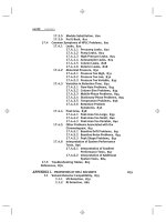
Figure 9.13 shows a practical sine wave oscillator
based on a three-stage C–R ladder network. The
circuit provides an output of approximately 1V pkpk at 1.97 kHz.
Figure 9.13 A practical sine wave oscillator based
on a phase shift ladder network
A practical Wien bridge oscillator is shown in Fig.
9.14. This circuit produces a sine wave output at 16
Hz. The output frequency can easily be varied by
making Rl and R2 a l0 kL dual-gang potentiometer
and connecting a fixed resistor of 680 L in series
with each. In order to adjust the loop gain for an
optimum sine wave output it may be necessary to
make R3/R4 adjustable. One way of doing this is to
replace both components with a 10 kL multi-turn
potentiometer with the sliding contact taken to the
inverting input of IC1.
Figure 9.15 A practical square wave oscillator
based on an astable multivibrator
OSCILLATORS
179
Practical investigation
Objective
To investigate a simple operational amplifier
astable oscillator.
Components and test equipment
Breadboard, oscilloscope, ±9 V d.c. power supply
(or two 9 V batteries), 741CN (or similar
operational amplifier), 10 n, 22 n, 47 n and 100 n
capacitors, resistors of 100 kL, 1 kL and 680 L
5% 0.25 W, test leads, connecting wire.
Figure 9.16 A practical triangle wave generator
Procedure
Connect the circuit shown in Fig. 9.19 with C = 47
nF. Set the oscilloscope timebase to the 2 ms/cm
range and Y-attenuator to 1 V/cm. Adjust the
oscilloscope so that it triggers on a positive edge
and display the output waveform produced by the
oscillator. Make a sketch of the waveform using the
graph layout shown in Fig. 9.20.
Measure and record (using Table 9.1) the time
for one complete cycle of the output. Repeat this
measurement with C = 10 nF, 22 nF and 100 nF.
Calculations
Figure 9.17 A single-stage astable oscillator that
produces a square wave output
For each value of C, calculate the periodic time of
the oscillator’s output and compare this with the
measured values.
Figure 9.18 A practical high-frequency crystal
oscillator
Figure 9.19 Astable oscillator circuit used in the
Practical investigation
180
ELECTRONIC CIRCUITS: FUNDAMENTALS AND APPLICATIONS
Conclusion
Comment on the performance of the astable
oscillator. Is this what you would expect? Do the
measured values agree with those obtained by
calculation? If not, suggest reasons for any
differences. Suggest typical applications for the
circuit.
Table 9.1
C
Table of results and calculated values
Measured
periodic time
Calculated
periodic time
Important formulae introduced in this
chapter
Gain with positive feedback
(page 171):
G =
Av
1 0 Av
Loop gain:
(page 171)
L = 0Av
Output frequency of a three-stage C–R ladder
network oscillator:
(page 172)
10 nF
22 nF
47 nF
f =
100 nF
1
2K × 6CR
Output frequency of a Wien bridge oscillator:
(page 173)
f =
1
2K CR
Time for which a multivibrator output is ‘high’:
(page 175)
T1 = 0.7 C2 R4
Time for which a multivibrator output is ‘low’:
(page 175)
T2 = 0.7 C1 R3
Figure 9.20
Graph layout for sketching the
output waveform produced by the astable oscillator
Periodic time for the output of a square wave
mutivibrator:
(pages 175 and 176)
T = 0.7 (C2 R4 + C1 R3)
when C = C1 = C2 and R = R3 = R4
Symbol introduced in this chapter
T = 1.4 C R
Periodic time for the output of a single-stage
astable oscillator:
(page 177)
T = 2CR ln 1 + 2
Figure 9.21
Symbol introduced in this chapter
R2
R1
OSCILLATORS
Problems
9.1
9.2
9.3
9.4
9.5
9.6
9.7
9.8
9.9
9.10
9.11
9.12
An amplifier with a gain of 8 has 10% of its
output fed back to the input. Determine the
gain of the stage (a) with negative
feedback, (b) with positive feedback.
A phase-shift oscillator is to operate with
an output at 1 kHz. If the oscillator is based
on a three-stage ladder network, determine
the required values of resistance if three
capacitors of 10 nF are to be used.
A Wien bridge oscillator is based on the
circuit shown in Fig. 9.4 but Rl and R2 are
replaced by a dual-gang potentiometer. If
C1 = C2 = 22 nF determine the values of
Rl and R2 required to produce an output at
exactly 400 Hz.
Determine the peak-peak voltage developed
across C1 in the oscillator circuit shown in
Fig. 9.22.
Determine the periodic time and frequency
of the output signal produced by the
oscillator circuit shown in Fig. 9.22.
An astable multivibrator circuit is required
to produce an asymmetrical rectangular
output which has a period of 4 ms and is to
be ‘high’ for 1 ms and ‘low’ for 3 ms. If the
timing capacitors are both to be 100 nF,
determine the values of the two timing
resistors required.
Explain, briefly,
how the
astable
multivibrator shown in Fig. 9.23 operates.
Illustrate your answer using a waveform
sketch.
Determine the output frequency of the
signal produced by the circuit shown in Fig.
9.23.
Explain, briefly, how the Wien bridge
oscillator shown in Fig. 9.24 operates.
What factors affect the choice of values for
R3 and R4?
Determine the output frequency of the
signal produced by the circuit shown in Fig.
9.24.
Sketch the circuit of an oscillator that will
produce a triangular waveform output.
Explain briefly how the circuit operates and
suggest a means of varying the output
frequency over a limited range.
Distinguish between the following types of
mulitivibrator circuit:
Figure 9.22
See Questions 9.4 and 9.5.
Figure 9.23
See Questions 9.7 and 9.8.
Figure 9.24
See Questions 9.9 and 9.10.
181
182
9.13
ELECTRONIC CIRCUITS: FUNDAMENTALS AND APPLICATIONS
(a) astable multivibrators, (b) monostable
multivibrators, (c) bistable multivibrators.
Derive an expression (in terms of R3 and
R4) for the minimum value of voltage gain
required to produce oscillation in the circuit
shown in Fig. 9.25.
Figure 9.25
Figure 9.26
See Question 9.14
Figure 9.27
See Question 9.15
Figure 9.28
See Question 9.16
See Question 9.13
9.14
Design an oscillator circuit that will
generate the output waveform shown in
Fig. 9.26. Sketch a circuit diagram for the
oscillator and specify all component values
(including supply voltage). Give reasons
for your choice of oscillator circuit.
9.15 Design an oscillator circuit that will
generate the output waveform shown in
Fig. 9.27. Sketch a circuit diagram for the
oscillator and specify all component values
(including supply voltage). Give reasons
for your choice of oscillator circuit.
9.16 Design an oscillator circuit that will
generate the output waveform shown in
Fig. 9.28. Sketch a circuit diagram for the
oscillator and specify all component values
(including supply voltage). Give reasons
for your choice of oscillator circuit.
9.17 Briefly explain the term ‘piezoelectric
effect’.
9.18 Sketch the circuit diagram of simple singlestage crystal oscillator and explain the
advantages of using a quartz crystal as the
frequency determining element.
Answers to these problems appear on page 375.
10
Logic circuits
This chapter introduces electronic circuits and
devices that are associated with digital rather than
analogue circuitry. These logic circuits are used
extensively in digital systems and form the basis of
clocks, counters, shift registers and timers.
The chapter starts by introducing the basic logic
functions (AND, OR, NAND, NOR, etc.) together
with the symbols and truth tables that describe the
operation of the most common logic gates. We then
show how these gates can be used in simple
combinational logic circuits before moving on to
introduce bistable devices, counters and shift
registers. The chapter concludes with a brief
introduction to the two principal technologies used
in modern digital logic circuits, TTL and CMOS.
Logic functions
Electronic logic circuits can be used to make
simple decisions like:
If dark then put on the light.
and
If temperature is less then 20°C then connect
the supply to the heater.
They can also be used to make more complex
decisions like:
implemented using straightforward electronic
circuits. Because this circuitry is based on discrete
states and since the behaviour of the circuits can be
described by a set of logical statements, it is
referred to as digital logic.
Switch and lamp logic
In the simple circuit shown in Fig. 10.1 a battery is
connected to a lamp via a switch. There are two
possible states for the switch, open and closed but
the lamp will only operate when the switch is
closed. We can summarize this using Table 10.1.
Since the switch can only be in one of the two
states (i.e. open or closed) at any given time, the
open and closed conditions are mutually exclusive.
Furthermore, since the switch cannot exist in any
other state than completely open or completely
closed (i.e. there is no intermediate or half-open
state) the circuit uses binary or ‘two-state’ logic.
The logical state of the switch can be represented
by the binary digits, 0 and 1. For example, if
logical 0 is synonymous with open (or ‘off’) and
logical 1 is equivalent to closed (or ‘on’), then:
Switch open (off) = 0
Switch closed (on) = 1
If ‘hour’ is greater than 11 and ‘24 hour clock’
is not selected then display message ‘pm’.
All of these logical statements are similar in form.
The first two are essentially:
Figure 10.1 Simple switch and lamp circuit
If {condition} then {action}.
while the third is a compound statement of the
form:
If {condition 1} and not {condition 2} then
{action}.
Both
of
these
statements
can
be
readily
Table 10.1 Simple switching logic
Condition
Switch
Comment
1
Open
No light produced
2
Closed
Light produced
184
ELECTRONIC CIRCUITS: FUNDAMENTALS AND APPLICATIONS
We can now rewrite the truth table in terms of the
binary states as shown in Fig. 10.2 where:
No light (off) = 0
Light (on) = 1
Figure 10.2 Truth table for the switch and lamp
Figure 10.3 AND switch and lamp logic
Table 10.2 Simple AND switching logic
Condition Switch A
Switch B
Comment
1
Open
Open
No light produced
2
Open
Closed
No light produced
3
Closed
Open
No light produced
4
Closed
Closed
Light produced
AND logic
Now consider the circuit with two switches shown
in Fig. 10.3. Here the lamp will only operate when
switch A is closed and switch B is closed.
However, let’s look at the operation of the circuit in
a little more detail.
Since there are two switches (A and B) and there
are two possible states for each switch (open or
closed), there is a total of four possible conditions
for the circuit. We can summarize these conditions
in Table 10.2.
Since each switch can only be in one of the two
states (i.e. open or closed) at any given time, the
open and closed conditions are mutually exclusive.
Furthermore, since the switches cannot exist in any
other state than completely open or completely
closed (i.e. there are no intermediate states) the
circuit uses binary logic. We can thus represent the
logical states of the two switches by the binary
digits, 0 and 1.
Once again, if we adopt the convention that an
open switch can be represented by 0 and a closed
switch by 1, we can rewrite the truth table in terms
of the binary states shown in Fig. 10.4 where:
No light (off) = 0
Light (on) = 1
OR logic
Figure 10.4 Truth table for the switch and lamp
Figure 10.5 OR switch and lamp logic
Figure 10.5 shows another circuit with two
switches. This circuit differs from that shown in
Fig. 10.3 by virtue of the fact that the two switches
are connected in parallel rather than in series. In
this case the lamp will operate when either of the
two switches is closed. As before, there is a total of
four possible conditions for the circuit. We can
summarize these conditions in Table 10.3.
Once again, adopting the convention that an
open switch can be represented by 0 and a closed
switch by 1, we can rewrite the truth table in terms
of the binary states as shown in Fig. 10.6.
LOGIC CIRCUITS
Table 10.3 Simple OR switching logic
185
Example 10.1
Figure 10.7 shows a simple switching circuit.
Describe the logical state of switches A, B, and C
in order to operate the lamp. Illustrate your answer
with a truth table.
Condition Switch A
Switch B
Comment
1
Open
Open
No light produced
2
Open
Closed
Light produced
3
Closed
Open
Light produced
Solution
4
Closed
Closed
Light produced
In order to operate the lamp, switch A and either
switch B or switch C must be operated. The truth
table is shown in Fig. 10.8.
Logic gates
Figure 10.6 Truth table for OR logic
Logic gates are circuits designed to produce the
basic logic functions, AND, OR, etc. These circuits
are designed to be interconnected into larger, more
complex, logic circuit arrangements. Since these
circuits form the basic building blocks of all digital
systems, we have summarized the action of each of
the gates in the next section. For each gate we have
included its British Standard (BS) symbol together
with its American Standard (MIL/ANSI) symbol.
We have also included the truth tables and Boolean
expressions (using ‘+’ to denote OR, ‘·’ to denote
AND, and ‘E’ to denote NOT). Note that, while
inverters and buffers each have only one input,
exclusive-OR gates have two inputs and the other
basic gates (AND, OR, NAND and NOR) are
commonly available with up to eight inputs.
Figure 10.7 See Example 10.1
Buffers (Fig. 10.9)
Buffers do not affect the logical state of a digital
signal (i.e. a logic 1 input results in a logic 1 output
whereas a logic 0 input results in a logic 0 output).
Buffers are normally used to provide extra current
drive at the output but can also be used to
regularize the logic levels present at an interface.
The Boolean expression for the output, Y, of a
buffer with an input, X, is:
Y=X
Inverters (Fig. 10.10)
Figure 10.8 See Example 10.1
Inverters are used to complement the logical state
(i.e. a logic 1 input results in a logic 0 output and
186
ELECTRONIC CIRCUITS: FUNDAMENTALS AND APPLICATIONS
vice versa). Inverters also provide extra current
drive and, like buffers, are used in interfacing
applications where they provide a means of
regularizing logic levels present at the input or
output of a digital system. The Boolean expression
for the output, Y, of a buffer with an input, X, is:
Y = X
Figure 10.9 Symbols and truth table for a buffer
AND gates (Fig. 10.11)
AND gates will only produce a logic 1 output when
all inputs are simultaneously at logic 1. Any other
input combination results in a logic 0 output. The
Boolean expression for the output, Y, of an AND
gate with inputs, A and B, is:
Y =A B
Figure 10.10
inverter
Symbols and truth table for an
OR gates (Fig. 10.12)
OR gates will produce a logic 1 output whenever
any one, or more, inputs are at logic 1. Putting this
another way, an OR gate will only produce a logic
0 output whenever all of its inputs are
simultaneously at logic 0. The Boolean expression
for the output, Y, of an OR gate with inputs, A and
B, is:
Figure 10.11 Symbols and truth table for an AND
gate
Y = A+B
NAND gates (Fig. 10.13)
NAND (i.e. NOT-AND) gates will only produce a
logic 0 output when all inputs are simultaneously at
logic 1. Any other input combination will produce a
logic 1 output. A NAND gate, therefore, is nothing
more than an AND gate with its output inverted!
The circle shown at the output denotes this
inversion. The Boolean expression for the output,
Y, of a NAND gate with inputs, A and B, is:
Figure 10.12 Symbols and truth table for an OR
gate
Y=A B
NOR gates (Fig. 10.14)
NOR (i.e. NOT-OR) gates will only produce a
logic 1 output when all inputs are simultaneously at
logic 0. Any other input combination will produce a
Figure 10.13 Symbols and truth table for a NAND
gate
LOGIC CIRCUITS
187
logic 0 output. A NOR gate, therefore, is simply an
OR gate with its output inverted. A circle is again
used to indicate inversion. The Boolean expression
for the output, Y, of a NOR gate with inputs, A and
B, is:
Y = A+B
Exclusive-OR gates (Fig. 10.15)
Figure 10.14 Symbols and truth table for a NOR
gate
Exclusive-OR gates will produce a logic 1 output
whenever either one of the inputs is at logic 1 and
the other is at logic 0. Exclusive-OR gates produce
a logic 0 output whenever both inputs have the
same logical state (i.e. when both are at logic 0 or
both are at logic 1). The Boolean expression for the
output, Y, of an exclusive-OR gate with inputs, A
and B, is:
Y = A B +B A
Figure 10.15 Symbols and truth table for an
exclusive-OR gate
Combinational logic
By using a standard range of logic levels (i.e.
voltage levels used to represent the logic 1 and
logic 0 states) logic circuits can be combined
together in order to solve complex logic functions.
Example 10.2
A logic circuit is to be constructed that will produce
a logic 1 output whenever two, or more, of its three
inputs are at logic 1.
Figure 10.16 See Example 10.2
Solution
This circuit could be more aptly referred to as a
majority vote circuit. Its truth table is shown in
Fig. 10.16. Figure 10.17 shows the logic circuitry
required.
Example 10.3
Show how an arrangement of basic logic gates
(AND, OR and NOT) can be used to produce the
exclusive-OR function.
Figure 10.17 See Example 10.2
188
ELECTRONIC CIRCUITS: FUNDAMENTALS AND APPLICATIONS
Solution
In order to solve this problem, consider the Boolean
expression for the exclusive-OR function:
Y = A B + B. A
This expression takes the form:
Y = P + Q where P = A B and Q = B A
Figure 10.18 See Example 10.3
A B and Q = B A can be obtained using two
two-input AND gates and the result (i.e. P and Q)
can then be applied to an OR gate with two inputs.
A and B can be produced using inverters. The
complete solution is shown in Fig. 10.18.
Bistables
The output of a bistable has two stables states
(logic 0 or logic 1) and, once set in one or other of
these states, the device will remain at a particular
logic level for an indefinite period until reset. A
bistable thus constitutes a simple form of ‘memory
cell’ because it will remain in its latched state
(whether set or reset) until a signal is applied to it
in order to change its state (or until the supply is
disconnected).
R-S bistables
The simplest form of bistable is the R-S bistable.
This device has two inputs, SET and RESET, and
complementary outputs, Q and Q . A logic 1 applied
to the SET input will cause the Q output to become
(or remain at) logic 1 while a logic 1 applied to the
RESET input will cause the Q output to become (or
remain at) logic 0. In either case, the bistable will
remain in its SET or RESET state until an input is
applied in such a sense as to change the state.
Two simple forms of R-S bistable based on
cross-coupled logic gates are shown in Fig. 10.19.
Figure 10.19(a) is based on NAND gates while Fig.
10.19(b) is based on NOR gates.
The simple cross-coupled logic gate bistable has
a number of serious shortcomings (consider what
Figure 10.19 R-S bistables using cross-coupled
NAND and NOR gates
would happen if a logic 1 was simultaneously
present on both the SET and RESET inputs!) and
practical forms of bistable make use of much
improved purpose-designed logic circuits such as
D-type and J-K bistables.
D-type bistables
The D-type bistable has two inputs: D (standing
variously for ‘data’ or ‘delay’) and CLOCK (CLK).
The data input (logic 0 or logic 1) is clocked into
the bistable such that the output state only changes
LOGIC CIRCUITS
when the clock changes state. Operation is thus said
to be synchronous. Additional subsidiary inputs
(which are invariably active low) are provided
which can be used to directly set or reset the
bistable. These are usually called PRESET (PR)
and CLEAR (CLR). D-type bistables are used both
as latches (a simple form of memory) and as binary
dividers. The simple circuit arrangement in Fig.
10.20 together with the timing diagram shown in
Fig. 10.21 illustrate the operation of D-type
bistables.
Figure 10.20 D-type bistable operation
189
0 on the PRESET input will set the Q output to 1
whereas a 0 on the CLEAR input will set the Q
output to 0). Tables 10.4 and 10.5 summarize the
operation of a J-K bistable respectively for the
PRESET and CLEAR inputs and for clocked
operation.
Table 10.4 Input and output states for a J-K
bistable (PRESET and CLEAR inputs)
Inputs
Output
PRESET CLEAR
QN+1
Comments
0
0
?
Indeterminate
0
1
0
Q output changes to 0
(i.e. Q is reset) regardless
of the clock state
1
0
1
Q output changes to 1
(i.e. Q is set) regardless
of the clock state
1
1
Enables clocked
See below operation (refer to Table
10.5)
Note: The preset and clear inputs operate regardless of
the clock.
Table 10.5 Input and output states for a J-K
bistable (clocked operation)
Inputs
Figure 10.21 Timing diagram for the D-type
bistable
Output
K
QN+1
0
0
QN
0
1
0
Q output changes to 0
(i.e. Q is reset) on the
next clock transition
1
0
1
Q output changes to 1
(i.e. Q is set) on the next
clock transition
1
1
QN
Q output changes to the
opposite state on the next
clock transition
J-K bistables
J-K bistables have two clocked inputs (J and K),
two direct inputs (PRESET and CLEAR), a
CLOCK (CK) input, and outputs (Q and Q). As
with R-S bistables, the two outputs are
complementary (i.e. when one is 0 the other is 1,
and vice versa). Similarly, the PRESET and
CLEAR inputs are invariably both active low (i.e. a
Comments
J
No change in state of the
Q output on the next
clock transition
Note: QN+1 means ‘Q after the next clock transition’
while QN means ‘Q in whatever state it was before’.
190
ELECTRONIC CIRCUITS: FUNDAMENTALS AND APPLICATIONS
J-K bistables are the most sophisticated and
flexible of the bistable types and they can be
configured in various ways including binary
dividers, shift registers, and latches.
Figure 10.22 shows the arrangement of a fourstage binary counter based on J-K bistables. The
timing diagram for this circuit is shown in Fig.
10.23. Each stage successively divides the clock
input signal by a factor of two. Note that a logic 1
input is transferred to the respective Q-output on
the falling edge of the clock pulse and all J and K
inputs must be taken to logic 1 to enable binary
counting.
Figure 10.24 shows the arrangement of a fourstage shift register based on J-K bistables. The
timing diagram for this circuit is shown in Fig.
10.25. Note that each stage successively feeds data
to the next stage. Note that all data transfer occurs
on the falling edge of the clock pulse.
Example 10.4
A logic arrangement has to be designed so that it
produces the pulse train shown in Fig. 10.27.
Devise a logic circuit arrangement that will
Figure 10.22 Four-stage binary counter using J-K bistables
Figure 10.23 Timing diagram for the four-stage binary counter shown in Fig. 10.22
LOGIC CIRCUITS
191
Figure 10.24 Four-stage shift register using J-K bistables
Figure 10.27 See Example 10.4
generate this pulse train from a regular square wave
input.
Solution
Figure 10.25 Timing diagram for the four-stage
shift register shown in Fig. 10.24
Figure 10.26 See Example 10.4
A two-stage binary divider (based on J-K bistables)
can be used together with a two-input AND gate as
shown in Fig. 10.26. The waveforms for this logic
arrangement are shown in Fig. 10.28.
192
ELECTRONIC CIRCUITS: FUNDAMENTALS AND APPLICATIONS
Figure 10.28
Waveforms
arrangement shown in Fig. 10.26
for
the
logic
The two basic logic families are CMOS
(complementary metal oxide semiconductor) and
TTL (transistor transistor logic). Each of these
families is then further sub-divided. Representative
circuits for a two-input AND gate in both
technologies are shown in Figs 10.29 and 10.30.
The most common family of TTL logic devices
is known as the 74-series. Devices from this family
are coded with the prefix number 74. Variants
within the family are identified by letters which
follow the initial 74 prefix, as shown in Table 10.6.
The most common family of CMOS devices is
known as the 4000-series. Variants within the
family are identified by the suffix letters given in
Table 10.7.
Table 10.6 TTL device coding—infix letters
Integrated circuit logic devices
The task of realizing a complex logic circuit is
made simple with the aid of digital integrated
circuits. Such devices are classified according to
the semiconductor technology used in their
fabrication (the logic family to which a device
belongs is largely instrumental in determining its
operational characteristics, such as power
consumption, speed, and immunity to noise).
The relative size of a digital integrated circuit (in
terms of the number of active devices that it
contains) is often referred to as its scale of
integration and the terminology in Table 10.5 is
commonly used.
Infix
Meaning
None
Standard TTL device
ALS
Advanced low-power Schottky
C
CMOS version of a TTL device
F
‘Fast’ (a high-speed version)
H
High-speed version
S
Schottky input configuration (improved
speed and noise immunity)
HC
High-speed CMOS version (CMOS compatible inputs)
HCT
High-speed CMOS version (TTL compatible inputs)
LS
Low-power Schottky
Table 10.5 Scale of integration
Scale of
integration
Abbreviation
Number of logic
gates*
Small
SSI
1 to 10
Medium
MSI
10 to 100
Large
LSI
100 to 1,000
Very large
VLSI
1,000 to 10,000
Super large
SLSI
10,000 to 100,000
* or active circuitry of equivalent complexity
Table 10.7
CMOS device coding—the most
common variants of the 4000 family are identified
using these suffix letters
Infix
Meaning
None
Standard CMOS device
A
Standard (unbuffered) CMOS device
B, BE
Improved (buffered) CMOS device
UB, UBE
Improved (unbuffered) CMOS device
LOGIC CIRCUITS
193
Example 10.5
Identify each of the following integrated circuits:
(i) 4001UBE;
(ii) 74LS14.
Solution
Integrated circuit (i) is an improved (unbuffered)
version of the CMOS 4001 device. Integrated
circuit (ii) is a low-power Schottky version of the
TTL 7414 device.
Date codes
It is also worth noting that the vast majority of
logic devices and other digital integrated circuits
are marked with a four digit date code. The code
often appears alongside or below the device code.
The first two digits of this code give the year of
manufacture while the last two digits specify the
week of manufacture.
Figure 10.29 Two-input TTL NAND gate
Example 10.6
An integrated circuit marked ‘4050B 9832’. What
type of device is it and when was it manufactured?
Solution
The device is a buffered CMOS 4050 manufactured
in the 32nd week of 1998.
Figure 10.30 Two-input CMOS NAND gate
Logic levels
Logic levels are simply the range of voltages used
to represent the logic states 0 and 1. The logic
levels for CMOS differ markedly from those
associated with TTL. In particular, CMOS logic
levels are relative to the supply voltage used while
the logic levels associated with TTL devices tend to
be absolute (see Table 10.8).
Table 10.8 Logic levels for CMOS and TTL logic
devices
Condition
CMOS
TTL
Logic 0
Less than 1/3VDD
More than 2 V
Logic 1
More than 2/3VDD
Less than 0.8 V
Between 0.8 V
and 2 V
Noise margin
Indeterminate Between 1/3VDD
and 2/3VDD
The noise margin of a logic device is a measure of
its ability to reject noise and spurious signals; the
Note: VDD is the positive supply associated with CMOS
devices
194
ELECTRONIC CIRCUITS: FUNDAMENTALS AND APPLICATIONS
The noise margin for standard 7400 series TTL is
typically 400 mV while that for CMOS is 1/3VDD,
as shown in Fig. 10.31.
Table 10.9 compares the more important
characteristics of common members of the TTL
family with their buffered CMOS logic
counterparts. Finally, Fig. 10.32 shows the
packages and pin connections for two common
logic devices, the 74LS00 (quad two-input NAND
gate) and the 4001UBE (quad two-input NOR
gate).
Figure 10.31 Logic levels and noise margins for
TTL and CMOS devices
larger the noise margin the better is its ability to
perform in an environment in which noise is
present. Noise margin is defined as the difference
between the minimum values of high state output
and high state input voltage and the maximum
values of low state output and low state input
voltage. Hence:
Noise margin = VOH(MIN) R VIH(MIN)
or
Noise margin = VOL(MAX) R VOH(MAX)
where VOH(MIN) is the minimum value of high state
(logic 1) output voltage, VIH(MIN) is the minimum
value of high state (logic 1) input voltage, VOL(MAX)
is the maximum value of low state (logic 0) output
voltage, and VOH(MAX) is the maximum value of low
state (logic 0) input voltage.
Figure 10.32 Packages and pin connections for
two common logic devices
Example 10.7
Show how a 4001UBE device (see Fig. 10.32) can
be connected to form a simple cross-coupled
bistable. Sketch a circuit diagram showing pin
connections and include LEDs that will indicate the
output state of the bistable.
Solution
See Practical investigation on Page 195. Note that
only two of the four logic gates have been used.
LOGIC CIRCUITS
195
Table 10.9 Characteristics of common logic families
Characteristic
Logic family
74
74LS
74HC
40BE
Maximum supply voltage (V)
5.25
5.25
5.5
18
Minimum supply voltage (V)
4.75
4.75
4.5
3
Static power dissipation (mW per gate at 100 kHz)
10
2
negligible
negligible
Dynamic power dissipation (mW per gate at 100 kHz)
10
2
0.2
0.1
Typical propagation delay (ns)
10
10
10
105
Maximum clock frequency (MHz)
35
40
40
12
Speed-power product (pJ at 100 kHz)
100
20
1.2
11
Minimum output current (mA at VO = 0.4 V)
16
8
4
1.6
Fan-out (number of standard loads that can be driven)
40
20
10
4
Maximum input current (mA at VI = 0.4 V)
R1.6
R0.4
0.001
R0.001
Practical investigation
Objective
To investigate the operation of a simple bistable
based on cross-coupled NOR gates.
Components and test equipment
Breadboard, 9 V d.c. power supply (or a 9 V
battery), 4001BE quad two-input buffered CMOS
NOR gate, red and green LEDs, operational
amplifier), two 1 kT and two 47 kT 5% 0.25 W
resistors, test leads, connecting wire.
Procedure
Figure 10.33 Bistable circuit used in the Practical
investigation. The LEDs are used to indicate the
state of the outputs
Connect the circuit shown in Fig. 10.33 (see also
Fig. 10.34 for the corresponding breadboard
layout). Note that the green LED should become
illuminated when the bistable is in the SET
condition (i.e. when Q is at logic 1) and the red
LED should become illuminated when the bistable
is in the RESET condition. Note also that the 47 k
resistors act as pull-up resistors. They are used to
ensure that the respective input goes to logic 1
when the corresponding link is removed.
With both links in place (i.e. SET = 0 and
RESET = 0) observe and record (using a truth
table) the state of the outputs.
Remove the RESET link (to make RESET = 1)
whilst leaving the SET link in place (to keep SET =
0). Once again, observe and record the state of the
outputs. Replace the RESET link (to make RESET
= 0) and check that the bistable does not change