Research on dynamical buckling of imperfect stiffened three layered toroidal shell segments containing fluid under mechanical loads
Bạn đang xem bản rút gọn của tài liệu. Xem và tải ngay bản đầy đủ của tài liệu tại đây (2.75 MB, 20 trang )
Acta Mech
DOI 10.1007/s00707-016-1724-0
O R I G I NA L PA P E R
Dao Huy Bich · Dinh Gia Ninh
Research on dynamical buckling of imperfect stiffened
three-layered toroidal shell segments containing fluid under
mechanical loads
Received: 17 June 2016
© Springer-Verlag Wien 2016
Abstract An analytical approach to the nonlinear dynamical buckling of imperfect stiffened three-layered
toroidal shell segments containing fluid is performed in this paper. The toroidal shell segments are reinforced by
ring and stringer stiffeners system in which the material properties of the shell are assumed to be continuously
graded in the thickness direction. Based on the classical thin shell theory with geometrical nonlinearity in
von Karman–Donnell sense, Stein and McElman assumption, theoretical formulations are derived with the
smeared stiffeners technique. Furthermore, the dynamical pressure of the fluid is taken into account. The fluid
is assumed to be non-viscous and ideally incompressible. The dynamical critical buckling loads are evaluated
by the Budiansky–Roth criterion in three cases: axial compression and lateral pressure with movable and
immovable boundary conditions are obtained using the Galerkin method. Moreover, effects of geometrical and
material parameters, imperfection and fluid on the nonlinear dynamical buckling behavior of shells are shown
in the obtained results.
1 Introduction
The problems of structures containing fluid have been attracting vast attention of researchers around the
world. Chen et al. [1] investigated the vibration of fluid-filled orthotropic FGM cylindrical shells based on the
three-dimensional fundamental equations of anisotropic elasticity. The frequency equation was deduced for
an FGM cylindrical shell filled with a compressible, non-viscous fluid medium. The vibration analysis of a
functionally graded (FG) rectangular plate partially in contact with a bounded fluid was given by Khorshidi and
Bakhsheshy [2]. The fluid velocity potential satisfying fluid boundary conditions was derived, and wet dynamic
modal functions of the plate were expanded in terms of finite Fourier series for compatibility requirements along
the contacting surface between the plate and the fluid. Sheng and Wang [3] proposed an investigation into the
vibration of FGM cylindrical shells with flowing fluid in an elastic medium under mechanical and thermal loads.
Based on the first-order shear deformation theory (FSDT) and the fluid velocity potential, the dynamic equation
of functionally graded cylindrical shells with flowing fluid was derived. The equations of the eigenvalue problem
were obtained by using a modal expansion method. A numerical analysis of stability of a stationary or rotating
circular cylindrical shell containing axially flowing and rotating fluid was investigated by Bochkarev and
Matveenko [4]. The form of stability loss in stationary and rotating shells under the action of the fluid flow,
having both axial and circumferential components, depended on the type of the boundary conditions specified
D. H. Bich
Department of Mathematics, Mechanics and Informatics, Vietnam National University, No. 144 Xuan Thuy Street,
Cau Giay District, Hanoi, Vietnam
D. G. Ninh (B)
School of Mechanical Engineering, Hanoi University of Science and Technology, Hanoi, Vietnam
E-mail: ;
Tel.: 84 988 287 789
D. H. Bich, D. G. Ninh
at their ends. A theoretical and an experimental investigation carried out on a thin-walled hemi-ellipsoidal
prolate dome in air and also under external water pressure were given by Ross et al. [5]. The theoretical
investigation was carried out using the finite element analysis to model both the structure and the fluid. The
ANSYS program used 2 different doubly curved thin-walled shell elements, while the in-house program used
a simpler axisymmetric thin-walled shell element. This axisymmetric element allowed a sinusoidal variation
of the displacements in the circumferential direction, thus decreasing preparation and computational time.
Prado et al. [6] studied the dynamic instability of perfect simply supported orthotropic cylindrical shells
with internal flowing fluid and subjected to either a compressive axial static preload plus a harmonic axial
load or a harmonic lateral pressure. The fluid was assumed to be non-viscous and incompressible and the
flow, isentropic and irrotational. An expansion with eight degrees of freedom, containing the fundamental,
companion, gyroscopic, and four axisymmetric modes was used to describe the lateral displacement of the
shell. An analytical method to predict nondestructively the elastic critical pressure of a submerged cylindrical
shell which is subjected to external hydrostatic pressure was presented in Zhu et al. [7]. The structural–fluid
coupling dispersion equation of the system was established considering axial and lateral hydrostatic pressure
based on the wave propagation approach.
Furthermore, the sandwich structures have become of great interest in structural applications. The smooth
and continuous change in material properties enables sandwiched FGMs to avoid interface problems and
unexpected thermal stress concentrations. On the other hand, sandwich structures also have other mentionable
properties, especially thermal and sound insulation. Sburlati [8] proposed an analytical solution in the framework of elasticity theory to indicate the elastic bending response of axisymmetric circular sandwich panels with
functionally graded material cores and homogeneous face sheets. The elastic solution was obtained using a
Plevako representation, which reduced the problem to the search of potential functions satisfying linear fourthorder partial differential equations. Sofiyev et al. [9,10] studied the parametric instability of a simply supported
sandwich cylindrical shell with an FGM core under static and time-dependent periodic axial compressive loads
and the influences of shear stresses and rotary inertia on the vibration of FG-coated sandwich cylindrical shells
resting on a Pasternak elastic foundation. The static and free vibration behaviors of two types of sandwich
plates based on the three-dimensional theory of elasticity were carried out by Alibeigloo and Alizadeh [11].
By using differential equilibrium equations and/or equations of motion as well as constitutive relations, the
state-space differential equation was derived. Taibi et al. [12] investigated the deformation behavior of shear
deformable FG sandwich plates resting on a Pasternak foundation under thermo-mechanical loads. Xia and
Shen [13] investigated the small- and large-amplitude vibration of compressively and thermally post-buckled
sandwich plates with FGM face sheets in thermal environment using a higher-order shear deformation plate
theory. The formulations were based on a general von Karman-type equation that included a thermal effect, and
the equations of motion were solved by an improved perturbation technique. The free vibration of sandwich
plates with FGM face sheets in various thermal environments to improve high-order sandwich plate theory
was studied by Khalili and Mohammadi [14]. The governing equations of motion in free natural vibration
were derived using Hamilton’s principle. A new approach was used to reduce the equations of motion and
then solved them for both unsymmetric and symmetric sandwich plates. Wang and Shen [15] investigated the
nonlinear dynamic response of sandwich plates with FGM face sheets resting on elastic foundations in thermal
environments. The material properties of the FGM layers were assumed to be graded in the thickness direction
according to the Mori–Tanaka scheme.
The dynamic buckling problems for shell structures are investigated widely. Shariyat [16,17] presented
dynamic buckling of a prestressed, suddenly heated imperfect FGM cylindrical shell and dynamic buckling of
a mechanically loaded imperfect FGM cylindrical shell in thermal environment, with temperature-dependent
properties; dynamic buckling of imperfect FGM cylindrical shells with integrated surface-bonded sensor and
actuator layers subjected to some complex combinations of thermo-electromechanical loads. The general form
of Green’s strain tensor in curvilinear coordinates and a high-order shell theory were proposed. Furthermore,
the nonlinear dynamic buckling of FGM cylindrical shells under time-dependent axial load and radial load
using an energy method and the Budiansky–Roth criterion were presented by Huang and Han [18,19]. Bich et
al. [20,21] studied the nonlinear dynamic buckling of FGM cylindrical shells and shallow spherical shells in
thermal environment using the Galerkin procedure and Budiansky–Roth criterion. The dynamic instability of
simply supported, functionally graded (FG) truncated conical shells under static and time-dependent periodic
axial loads using the Galerkin method was analyzed by Sofiyev and Kuruoglu [22]. The domains of principal
instability were determined using Bolotin’s method. With the same above structures, Sofiyev [23] investigated
the dynamic buckling of truncated conical shells with FGM coatings subjected to a time-dependent axial load
in large deformation. The method of solution utilizes the superposition principle and the Galerkin procedure.
Research on dynamical buckling of imperfect stiffened three-layered toroidal shell
Donnell–Karman-type nonlinear differential equations for the truncated conical shell with FGCs are derived
and reduced to ordinary differential equations with time-dependent coefficient. The nonlinear dynamic of
imperfect FGM thick double shallow shells with piezoelectric actuators on elastic foundations under the
combination of electrical, thermal, mechanical and damping loading was given by Duc et al. [24]. Zhang and
Li [25] discussed dynamic buckling of FGM truncated conical shells subjected to normal impact loads using
the Galerkin procedure and Runge–Kutta integration to solve the nonlinear governing equations numerically.
The toroidal shell segment structures have been applied in mechanical engineering, aerospace engineering,
biomechanical engineering, and so forth. In the past, there were some studies about these structures. McElman
[26] investigated the eccentrically stiffened shallow shells of double curvature with the static and dynamic
behaviors in a NASA technical note. The initial post-buckling behavior of toroidal shell segments under several
loading conditions using Koiter’s general theory was studied by Hutchinson [27]. Stein and McElman [28]
pointed out the buckling of homogenous and isotropic toroidal shell segments. Recently, Bich et al. [29–33] has
investigated the stability buckling of functionally graded toroidal shell segment under mechanical load based
on the classical thin shell theory and the smeared stiffeners technique. Ninh and Bich [34] have just studied
the nonlinear thermal vibration of eccentrically stiffened ceramic–FGM–metal layer toroidal shell segments
surrounded by an elastic foundation.
To the best of the authors’ knowledge, this is the first time that the nonlinear dynamical buckling of
imperfect eccentrically stiffened three-layered toroidal shell segments fully filled with fluid is investigated.
The dynamical critical buckling loads are evaluated by the Budiansky–Roth criterion in three cases: axial
compression and lateral pressure with movable and immovable boundary conditions. Based on the classical
shell theory with the nonlinear strain-displacement relation of large deflection, the Galerkin method, Volmir’s
assumption and a numerical method using fourth-order Runge–Kutta are implemented for dynamic analysis of
shells. The fluid is assumed to be non-viscous and ideally incompressible. Effects of geometrical and material
parameters, imperfection and fluid on the nonlinear dynamical buckling behavior of shells are illustrated in
the obtained results.
2 Formulation of the problem
2.1 Three-layered composite (FGM core)
The sandwich toroidal shell segment of thickness h, length L, which is formed by rotation of a plane circular
arc of radius R about an axis in the plane of the curve as is shown in Fig. 1. The coordinate system (x, y, z)
is located on the middle surface of the shell, x and y are the axial and circumferential directions, respectively,
and z is the normal to the shell surface. The thickness of the shell is defined in a coordinate system (y, z) in
Fig. 2. The inner layer (z = h/2) and the outer layer (z = −h/2) are isotropic and homogenous with ceramic
and metal, respectively. Suppose that the material composition of the shell varies smoothly along the thickness
in such a way that the inner surface is ceramic, the outer surface is metal, and the core is FGM.
The thickness of the shell, ceramic rich and metal rich is h, h c , h m , respectively. Thus, the thickness of the
FGM core is h − h c − h m . The subscripts m and c refer to the metal and ceramic constituents, respectively.
Denote Vm and Vc as volume—fractions of metal and ceramic phases, respectively, where Vm + Vc = 1.
According to the mentioned law, the volume fraction is expressed as
⎧
h
h
⎪
⎨ Vc (z) = 0, − 2 ≤ z k≤ − 2 − h m ,
m
Vc (z) = z+h/2−h
, − h2 − h m ≤ z ≤
h−h c −h m
⎪
⎩
Vc (z) = 1, h2 − h c ≤ z ≤ h2 .
h
2
− h c , k ≥ 0,
According to the mentioned law, the Young modulus of the FGM core shell is expressed in the form
E(z) = E m Vm (z) + E c Vc (z) = E m + (E c − E m )Vc (z),
ρ(z) = ρm Vm (z) + ρc Vc (z) = ρm + (ρc − ρm )Vc (z),
and the Poisson ratio ν is assumed to be constant.
(1)
D. H. Bich, D. G. Ninh
Fig. 1 Coordinate system of the ES-FGM core toroidal shell segment containing fluid
Fig. 2 Material characteristic of the FGM core
2.2 Constitutive relations and governing equations
Consider a sufficiently shallow toroidal shell segment in the region of the equator of the torus as described in
Fig. 1. By the Stein and Mc Elman assumption [28], the angle ϕ between the axis of revolution and the normal
to the shell surface is approximately equal to π/2, thus
sin ϕ ≈ 1; cos ϕ ≈ 0; r = a − R(1 − sin ϕ) ≈ a,
and d x = Rdϕ, dy = adθ,
where a is the equator radius and θ is the circumferential angle.
Research on dynamical buckling of imperfect stiffened three-layered toroidal shell
Fig. 3 Geometry and coordinate system of a stiffened FGM core toroidal shell segment containing fluid a stringer stiffeners; b
ring stiffeners
The radius of arc R is positive with the convex toroidal shell segment and negative with the concave toroidal
shell segment.
Suppose the eccentrically stiffened FGM core toroidal shell segment is reinforced by string and ring
stiffeners. In order to provide continuity within the shell and stiffeners and easier manufacture, the homogeneous
stiffeners can be used. Because pure ceramic ones are brittle, we used metal stiffeners and put them on the
metal side of the shell. With the law indicated in (1), the outer surface is metal, so the external metal stiffeners
are put on the outer side of the shell. Figure 3 depicts the geometry and coordinate system of the stiffened
FGM core shell.
The von Karman-type nonlinear kinematic relation for the strain component across the shell thickness at
a distance z from the middle surface is of the form [35]
⎛
⎞ ⎛ 0⎞
⎞
⎛
εx
εx
χx
⎝ ε y ⎠ = ⎝ ε0y ⎠ − z ⎝ χ y ⎠ ,
(2)
γx y
2χx y
γz0
where εx0 and ε0y are normal strains,γx0y is the shear strain at the middle surface of the shell, χx and χ y are the
curvatures and χx y is the twist.
According to the classical shell theory, the strains at the middle surface and curvatures are related to the
displacement components u, v, w in the x, y, z coordinate directions as [35]
⎫
⎧
⎛ 2 ⎞
⎛ 0 ⎞ ⎪ ∂u − w + 1 ∂w 2 + ∂w ∂wo
⎛
⎞
∂ w
⎪
⎪
⎪
εx
R
2 ∂x
∂x ∂x
⎬
⎨ ∂x
χx
∂x2 ⎟
⎜
2
2
⎝ ε0y ⎠ = ∂v − w + 1 ∂w + ∂w ∂wo
⎝ χ y ⎠ = ⎜ ∂ w2 ⎟ ,
;
(3)
⎝
∂
y ⎠
∂
y
a
2
∂
y
∂
y
∂
y
⎪
⎪
⎪
χx y
γx0y
∂2w
⎭
⎩ ∂u + ∂v + ∂w ∂w + ∂w ∂wo + ∂w ∂wo ⎪
∂ x∂ y
∂y
∂x
∂x ∂y
∂x ∂y
∂y ∂x
where wo (x, y) is a known function representing initial imperfection of the shell.
From Eq. (3), the strains must be satisfied in the deformation compatibility equation
∂ 2 ε0y
∂ 2 γx0y
∂ 2w
∂ 2w
∂ 2 εx0
+
−
−
+
=−
2
2
2
∂y
∂x
∂ x∂ y
R∂ y
a∂ x 2
∂ 2w
∂ 2 wo
+
∂ x∂ y
∂ x∂ y
2
−
∂ 2 w ∂ 2 wo
+
∂x2
∂x2
∂ 2 w ∂ 2 wo
+
∂ y2
∂ y2
.
(4)
Hooke’s law for the toroidal shell segment is defined as
σxsh =
σ ysh =
σxshy =
E(z)
(ε + νε y ),
1−ν 2 x
E(z)
(ε + νεx ),
1−ν 2 y
E(z)
2(1+ν) γx y ,
(5)
and for the metal stiffeners
σxst = E m εx ; σ yst = E m ε y .
By integrating the stress–strain equations and their moments through the thickness of the shell and using the
smeared stiffeners technique, the expressions for force and moment resultants of a FGM core toroidal shell
segment can be obtained as [33,35]:
D. H. Bich, D. G. Ninh
Nx =
A11 +
E m A1
s1
N y = A12 εx0 + A22 +
εx0 + A12 ε0y − (B11 + C1 )χx − B12 χ y ,
E m A2
s2
ε0y − B12 χx − (B22 + C2 )χ y ,
N x y = A66 γx0y − 2B66 χx y ,
(6)
Mx = (B11 + C1 )εx0 + B12 ε0y − D11 +
E m I1
s1
χx − D12 χ y ,
M y = B12 εx0 + (B22 + C2 )ε0y − D12 χx − D22 +
E m I2
s2
χy ,
Mx y = B66 γx0y − 2D66 χx y ,
(7)
where Ai j , Bi j , Di j (i, j = 1, 2, 6) are extensional, coupling and bending stiffnesses of the shell without
stiffeners:
E1
E1ν
E1
, A12 =
, A66 =
,
2
2
1−ν
1−ν
2(1 + ν)
E2
E2 ν
E2
= B22 =
, B12 =
, B66 =
,
1 − ν2
1 − ν2
2(1 + ν)
E3
E3ν
E3
= D22 =
, D12 =
, D66 =
,
2
2
1−ν
1−ν
2(1 + ν)
A11 = A22 =
B11
D11
(8)
where
h/2
E1 =
E(z)dz = E 1 = E m h + E cm h c +
−h/2
h/2
E2 =
E cm h c h
E cm h 2c
E cm
−
+
2
2
k+1
E(z)zdz = E 2 =
−h/2
−
E cm (h − h c − h m )
,
k+1
h
− h c (h − h c − h m )
2
E cm
(h − h c − h m )2 ,
(k + 1)(k + 2)
h/2
E3 =
E(z)z 2 dz = E 3 =
−h/2
E cm
k+1
h
− hc
2
2
(h − h c − h m ) −
2E cm
E c h 3c
(h − h c − h m )3 +
(k + 1)(k + 2)(k + 3)
3
E c hh c h
3hh m h
Em 3
+
− hc +
− hm
hm +
2
2
3
2
2
h
− h c (h − h c − h m ) ,
×
2
2E cm
(k +1)(k +2)
h
− h c (h −h c − h m )2
2
+
+
h
Em
− hm
(h − h c − h m )3 − 3
3
2
in which E cm = E c − E m , and
E m A1 z 1
E m A2 z 2
, C2 = −
,
s1
s2
A 1 = h 1 d1 , A 2 = h 2 d2 ,
d1 h 31
d2 h 32
I1 =
+ A1 z 12 , I2 =
+ A2 z 22 .
12
12
C1 = −
Research on dynamical buckling of imperfect stiffened three-layered toroidal shell
The spacings of the stringer and ring stiffeners are denoted by s1 and s2 , respectively. The quantities A1 , A2
are the cross-sectional areas of the stiffeners, and I1 , I2 , z 1 , z 2 are the second moments of cross-sectional areas
and eccentricities of the stiffeners with respect to the middle surface of the shell, respectively.
The reverse relations are obtained from Eq. (6) as
∗
∗
εx0 = A∗22 N x − A∗12 N y + B11
χx + B12
χy ,
∗
∗
ε0y = A∗11 N y − A∗12 N x + B21
χx + B22
χy ,
∗
χx y .
γx0y = A∗66 N x y + 2B66
(9)
Substituting Eq. (9) into Eq. (7) yields
∗
∗
∗
∗
N x + B21
N y − D11
χx − D12
χy ,
Mx = B11
∗
∗
∗
∗
M y = B12 N x + B22 N y − D21 χx − D22 χ y ,
∗
∗
N x y − 2D66
χx y ,
Mx y = B66
(10)
where
E m A1
1
E m A2
A12 ∗
1
, A66 =
A22 +
,
, A∗22 =
, A∗12 =
s1
s2
A66
E m A1
E m A2
= A11 +
. A22 +
− A212 ,
s1
s2
∗
= A∗22 (B11 + C1 ) − A∗12 B12 , B22
= A∗11 (B22 + C2 ) − A∗12 B12 ,
B66
∗
∗
= A∗22 B12 − A∗12 (B22 + C2 ), B21
= A∗11 .B12 − A∗12 (B11 + C1 ), B66
=
,
A66
E m I1
∗
∗
= D11 +
− (B11 + C1 )B11
− B12 B21
,
s1
E m I2
∗
∗
= D22 +
− B12 B21
− (B22 + C2 )B22
,
s2
∗
∗
= D12 − (B11 + C1 )B12
− B12 B22
,
∗
∗
= D12 − B12 B11 − (B22 + C2 )B21 ,
∗
= D66 − B66 B66
.
A∗11 =
∗
B11
∗
B12
∗
D11
∗
D22
∗
D12
∗
D21
∗
D66
1
A11 +
The nonlinear equilibrium equations of a toroidal shell segment filled inside by an incompressible fluid
under a lateral pressure q and an axial compression p based on the classical shell theory are given by [35]:
∂ Nx y
∂ Nx
∂ 2u
+
= ρ1 2 ,
∂x
∂y
∂t
∂ Nx y
∂ Ny
∂ 2v
+
= ρ1 2 ,
∂x
∂y
∂t
∂ 2 Mx y
∂ 2 My
∂ 2 wo
∂ 2 Mx
∂ 2 w ∂ 2 wo
∂ 2w
+
2
+
N
+
+
+
+
2N
x
x
y
∂x2
∂ x∂ y
∂ y2
∂x2
∂x2
∂ x∂ y
∂ x∂ y
2
2
2
Ny
∂w
∂ w ∂ wo
Nx
∂ w
+
+
+ q = ρ1 2 + 2 ρ1 ε
− pL ,
+N y
+
∂ y2
∂ y2
R
a
∂t
∂t
(11)
where ε is the damping coefficient, pL is the dynamic fluid pressure acting on the shell and
ρ1 = ρm h + ρcm h c +
ρcm (h − h c − h m )
+ ρm
k+1
A1
A2
+
s1
s2
.
(12)
D. H. Bich, D. G. Ninh
2.3 The dynamic pressure of fluid acting on the shell
The dynamic pressure of fluid acting on shell is expressed as follows:
p L = −ρ L
∂ϕ L
,
∂t
(13)
where ρ L is the mass density of the fluid.
According to the Stein and McElman assumption [28], for a shallow toroidal shell segment the equation
of the fluid velocity potential can be written approximately in the cylindrical coordinate system (x, θ, r ) as
1 ∂ϕ L
∂ 2ϕL
1 ∂ϕ L
∂ 2ϕL
+
+
=0
+
+
∂r 2
r ∂r
r 2 ∂θ 2
∂x2
(14)
with the boundary condition
∂w
∂ϕ L
=−
∂r
∂t
at r = a.
(15)
ϕ L has to be finite when r = 0 and at x = 0; L it depends on the boundary condition of the shell. Supposing
the shell is simply supported at x = 0 and x = L, the vibration shape function of shell can be chosen as
w=
f mn (t) sin
mπ x
sinnθ.
L
(16)
Then, the solution of Eq. (14) can be expressed as
ϕL =
Amn (t)In
mπr
mπ x
sinnθ,
sin
L
L
(17)
in which In is the Bessel function of the first kind of order n.
Certainly substitution of Eq. (17) into the left side of Eq. (14) leads to the identity. Satisfying the boundary
condition (15) with the use of Eqs. (16), (17), we obtain
Amn (t) =
−L
d f mn
.
dt
mπ In mπa
L
Putting the just obtained result into Eq. (17) and comparing with Eq. (16) yields
ϕL = −
a In (λm ) ∂w
mπa
, (λm =
).
λm In (λm ) ∂t
L
(18)
Substituting Eq. (18) into the left side of Eq. (13), the expression of the dynamic fluid pressure acting on
the shell is obtained:
p L = −ρ L
in which m L =
ρ L a In (λm )
λm In (λm ) (m L
∂ϕ L
a In (λm ) ∂ 2 w
∂ 2w
=
m
,
= ρL
L
∂t
λm In (λm ) ∂t 2
∂t 2
is the mass of fluid corresponding to the vibration of the shell)
(19)
Research on dynamical buckling of imperfect stiffened three-layered toroidal shell
3 Nonlinear dynamic buckling analysis of fully fluid-filled imperfect FGM core toroidal shell segment
Putting the expression of dynamic fluid pressure (19) into Eq. (11) and using Volmir’s assumption [36]
ρ1 (∂ 2 u/∂t 2 ) → 0, ρ1 (∂ 2 v/∂t 2 ) → 0 because of u << w, v << w, we can rewrite the system of the
equations of motion (11) as follows:
∂ Nx y
∂ Nx
+
= 0,
∂x
∂y
∂ Nx y
∂ Ny
+
= 0,
∂x
∂y
∂ 2 My
∂ 2 Mx y
∂ 2 wo
∂ 2 Mx
∂ 2 w ∂ 2 wo
∂ 2w
+
+
+
2
+
N
+
+
2N
x
x
y
∂x2
∂ x∂ y
∂ y2
∂x2
∂x2
∂ x∂ y
∂ x∂ y
2
2
2
Ny
∂ w ∂ wo
∂ w
∂w
Nx
+
+ q = (ρ1 + m L ) 2 + 2 ρ1 ε
.
+ Ny
+
+
∂ y2
∂ y2
R
a
∂t
∂t
(20)
Two first equations of Eq. (20) are satisfied identically by introducing the stress function as:
Nx =
∂2 F
,
∂ y2
Ny =
∂2 F
,
∂x2
Nx y = −
∂2 F
.
∂ x∂ y
(21)
Substituting Eq. (9) into deformation compatibility Eq. (4) and substituting Eq. (10) into the third equation of
motion (20), taking into account expressions (3) and (21), yields a system of equations:
A∗11
4
4
∂4 F
∂ 4w
∂4 F
∗
∗
∗ ∂ F
∗ ∂ w
∗
∗
∗
+
(A
−
2
A
)
+
A
+
B
+
(B
+
B
−
2B
)
66
12
22
21
11
22
66
∂x4
∂ x 2∂ y2
∂ y4
∂x4
∂ x 2∂ y2
2
∂ 2w
1 ∂ 2w
1 ∂ 2w
∂ 2w ∂ 2w
∂ 4w
+
+
+
+
∂ y4
R ∂ y2
a ∂x2
∂ x∂ y
∂ x 2 ∂ y2
2
2
2
2
2
2
∂ w ∂ wo
∂ w ∂ wo
∂ w ∂ wo
−2
+
= 0,
+
2
2
∂ x∂ y ∂ x∂ y
∂x ∂y
∂ y2 ∂ x 2
4
∂ 2w
∂w
∂ 4w
∗ ∂ w
∗
∗
∗
+
(D
+
D
+
4D
)
+ D11
(ρ1 + m L ) 2 + 2ρ1 ε
12
21
66
∂t
∂t
∂x4
∂ x 2∂ y2
4
4
∂4 F
∗ ∂ w
∗ ∂ F
∗
∗
∗
+ D22
−
B
−
(B
+
B
−
2B
)
21
11
22
66
∂ y4
∂x4
∂ x 2∂ y2
4
2
2
2
2
∂ 2w
1∂ F
1∂ F
∂ F ∂ w ∂ 2 wo
∂ 2 wo
∂2 F
∗ ∂ F
− B12
−
−
−
+
+
+
2
∂ y4
R ∂ y2
a ∂x2
∂ y2 ∂ x 2
∂x2
∂ x∂ y ∂ x∂ y
∂ x∂ y
2
2
2
∂ F ∂ w ∂ wo
+
− 2
= q.
∂x
∂ y2
∂ y2
∗
+ B12
(22)
(23)
Equations (22) and (23) are the nonlinear governing equations used to investigate the nonlinear dynamic
buckling of fully fluid-filled imperfect eccentrically stiffened FGM core toroidal shell segments.
Depending on the type of loading and the in-plane behavior at the edge, three cases of boundary condition
can be considered.
Case 1: The shell is simply supported and subjected to axial compressive load N01 = − po h, where po is the
average axial stress on the shell edges. Then, the associated boundary conditions are
w = 0, Mx = 0, N x = N01 = − po h, N x y = 0 at x = 0; L .
(24)
Case 2: The shell is simply supported and freely movable in the axial direction. The shell is acted on by
lateral pressure uniformly distributed on the outer surface of shell. The boundary condition in this case is the
following:
w = 0, Mx = 0, N x = 0, N x y = 0 at x = 0; L .
(25)
D. H. Bich, D. G. Ninh
Case 3: The shell is simply supported with immovable edges and subjected to lateral pressure on the outer
surface of the shell. The boundary conditions for this case can be expressed as
u = 0, w = 0, Mx = 0, N x = N01 , N x y = 0 at x = 0; L ,
(26)
where N01 is the fictitious compressive edge load rendering the edge immovable.
With the consideration of compatibility of shell and fluid on the interacted shell surface, the deflection and
the imperfection of the shell can be expressed by:
w = f (t) sin γm x sin βn y,
wo = f o sin γm x sin βn y,
(27)
n
where γm = mπ
L ; βn = 2a and m, n are the half wave numbers along the x-axis and wave numbers along the
y-axis, respectively. f o is constant, f o can be put as: f o = μh(0 ≤ μ < 1), h is the thickness of shell.
Substituting Eq. (27) into the left side of Eq. (22), the solution for the stress function F of this equation
can be expressed as:
F = F1 cos 2γm x + F2 cos 2βn y − F3 sin γm x sin βn y + N01
y2
,
2
(28)
in which
F1 = F1∗ f ( f + 2 f o ),
F2 = F2∗ f ( f + 2 f o ),
F3 = F3∗ f,
F1∗ =
βn2
,
8γm2 A∗11
F2∗ =
γm2
,
8βn2 A∗22
F3∗ =
∗ γ 4 + 2(B ∗ + B ∗ − 2B ∗ )γ 2 β 2 + 16B ∗ β 4 − 4β 2 /R − γ 2 /a
B21
m
n
m
11
22
66 m n
12 n
.
A∗11 γm4 + 2(A∗66 − 2 A∗12 )γm2 βn2 + 16A∗22 βn4
Substituting Eq. (27) and (28) into the equations of motion (23) and then applying Galerkin’s procedure in the
range 0 ≤ x ≤ L; 0 ≤ y ≤ 2πa, we obtain the following equation:
(ρ1 + m L )
∂f
∂2 f
+ 2ρ1 ε
+ H1 f 3
2
∂t
∂t
+H2 f 2 + H3 f + No1 γm2 f + No1 γm2 f o − No1
δ1 δ2
2
δ1 δ2 2
−q
= 0,
Rγm βn Lπa
γm βn Lπa
(29)
in which
H1 = 2γm2 βn2 (F1∗ + F2∗ ),
H2 = 6γm2 βn2 f o (F1∗ + F2∗ ) +
2δ1 δ2
3γm βn Lπa
∗
∗
+ 16F2∗ βm4 B12
−
16F1∗ γm4 B21
4γm2 F1∗
4β 2 F ∗
− m 2
a
R
20 γm βn δ1 δ2 F3∗
,
9
Lπa
∗ 4
∗
∗
∗
∗ 4
γm + (D12
+ D21
+ 4D66
)γm2 βn2 + D22
βn
H3 = D11
+
βn2 ∗ γm2 ∗
F −
F + 4γm2 βn2 f o2 (F1∗ + F2∗ )
R 3
a 3
4γ 2 F ∗
4β 2 F ∗
20 γm βn δ1 δ2 f o F3∗
∗
∗
+ 16F2∗ βm4 B12
− m 1 − m 2 +
,
16F1∗ γm4 B21
a
R
9
Lπa
∗ 4 ∗
∗
∗
∗
∗ 4 ∗
+B21
γm F3 + (B11
+ B22
− 2B66
)γm2 βn2 F3∗ + B12
βn F3 −
+
4δ1 δ2 f o
3γm βn Lπa
δ1 = (−1)m − 1 and δ2 = (−1)n − 1.
Research on dynamical buckling of imperfect stiffened three-layered toroidal shell
Equation (29) is the equation of motion to investigate the nonlinear dynamical buckling of fully fluid-filled
imperfect three-layered toroidal shell segment.
Using the fourth-order Runge–Kutta method into Eq. (29) combined with the initial conditions, the nonlinear responses of fluid full-filled imperfect three-layered toroidal shell segments can be investigated.
The nonlinear dynamic buckling of the mentioned shells can be performed in three cases:
Case 1: the shell under compression varying as linear function of time, i.e., q = 0, N01 = − po h with
po = c1 t (c1 is a loading speed).
Case 2: the shell with movable edge under lateral pressure varying as linear function of time, i.e., N01 = 0,
q = c2 t (c2 is a loading speed).
Case 3: the shell with immovable edge under lateral pressure varying as linear function of time. In this
case, q = c2 t, N01 = 0, where N01 now plays a role as the fictitious compressive edge load rending the
edge immovable.
The condition expressing the immovability on the boundary edges, i.e., u = 0 at x = 0; L is fulfilled in the
average sense as
L 2πa
0
0
∂u
d xd y =
∂x
L 2πa
w 1
−
R
2
εx0 +
0
0
∂w
∂x
2
−
Using Eqs. (9), (21), (27) and (28), the integral becomes:
A∗22 βn F3∗ δ1 δ2
f + 2No1 A∗22 Lπa
γm
γm2 Lπa
f o f = 0 from here to give
2
−
A∗12 γm F3∗ δ1 δ2
βn
f −
No1 = −
∗ γ δ δ
B11
m 1 2
βn
γm2 2
f −
8A∗22
f −
∂w ∂wo
d xd y = 0.
∂x ∂x
∗ β δ δ
B12
n 1 2
γm
f +
δ 1 δ2
Rγm βn
(30)
f −
γm2 Lπa
4
f,
f2 −
(31)
where
=− −
A∗22 βn F3∗ δ1 δ2
A∗ γm F3∗ δ1 δ2
B ∗ γm δ 1 δ 2
B ∗ βn δ 1 δ 2
δ1 δ2
γ 2 Lπa
1
fo
.
+ 12
+ 11
+ 12
−
+ m
∗
γm
βn
βn
γm
Rγm βn
2
2 A22 Lπa
Substituting Eq. (31) into the equation of motion (29) yields
(ρ1 + m L )
∂f
δ1 δ2 2
∂2 f
+ 2ρ1 ε
+ H1∗ f 3 + H2∗ f 2 + H3∗ f − q
= 0,
2
∂t
∂t
γm βn Lπa
in which
H1∗ = 2γm2 βn2 (F1∗ + F2∗ ) + γm4 /(8A∗22 ),
H2∗ = 6γm2 βn2 f o (F1∗ + F2∗ ) +
−
2δ1 δ2
3γm βn Lπa
20 γm βn δ1 δ2 F3∗
−
9
Lπa
∗
∗
+ 16F2∗ βm4 B12
−
16F1∗ γm4 B21
γm2 − γm4 f o /(8A∗22 ) +
4γm2 F1∗
4β 2 F ∗
− m 2
a
R
δ 1 δ 2 γm
,
4Rβn Lπa A∗22
∗ 4
∗
∗
∗
∗ 4
γm + (D12
+ D21
+ 4D66
)γm2 βn2 + D22
βn
H3∗ = D11
βn2 ∗ γm2 ∗
F −
F
R 3
a 3
4γ 2 F ∗
4β 2 F ∗
∗
∗
+ 16F2∗ βm4 B12
− m 1 − m 2
16F1∗ γm4 B21
a
R
∗ 4 ∗
∗
∗
∗
∗ 4 ∗
+ B21
γm F3 + (B11
+ B22
− 2B66
)γm2 βn2 F3∗ + B12
βn F3 −
+ 4γm2 βn2 f o2 (F1∗ + F2∗ ) +
−
20 γm βn δ1 δ2 f o F3∗
−
9
Lπa
4δ1 δ2 f o
3γm βn Lπa
γm2 f o +
2δ1 δ2
.
Rγm βn Lπa
(32)
D. H. Bich, D. G. Ninh
Table 1 Comparisons of dynamic critical stress (MPa) of perfect un-stiffened FGM cylindrical shells under linear-time compression
Parameters
a/ h = 500, L/a = 2, k = 0.5
c = 100 MPa/s
c = 50 MPa/s
c = 10 MPa/s
a/ h = 500, L/a = 2, c = 100 MPa/s
k = 0.2
k = 1.0
k = 5.0
L/a = 2, k = 0.2, c = 100 MPa/s
a/ h = 800
a/ h = 600
a/ h = 400
Present
Huang and Han [18]
181.76 (2, 11)
180.45 (2, 11)
178.02 (1, 8)
181.67 (2, 11)
179.37 (2, 11)
177.97 (1, 8)
195.19 (2, 11)
170.25 (2, 11)
150.46 (2, 11)
194.94 (2, 11)
169.94 (2, 11)
150.25 (2, 11)
125.37 (2, 11)
162.43 (3, 14)
239.77 (5, 15)
124.91 (2, 12)
162.25 (3, 14)
239.18 (5, 15)
By solving Eq. (29) for each case 1 and case 2, respectively, and Eq. (32) for case 3, the dynamical critical
time tcr can be obtained according to Budiansky–Roth criterion [37].
The criterion is based on that, for large value of loading speed, the amplitude–time curve of obtained
displacement response increases sharply depending on time, and this curve obtains a maximum by passing
from the slope point and at the corresponding time t = tcr the stability loss occurs. Here t = tcr is called
critical time and the load corresponding to this critical time is called dynamic critical buckling load pcr = c1 tcr
(in case 1) or qcr = c2 tcr (in case 2 or 3), respectively.
4 Results and discussion
4.1 Validations
To the best of the authors’ knowledge, there are no any publications about dynamic buckling imperfect threelayered toroidal shell segments containing full-filled fluid. Thus, the results in this paper are compared with
an FGM cylindrical shell (i.e., a toroidal shell segment with R → ∞).
The results of dynamic buckling of perfect un-stiffened FGM cylindrical shells subjected to linear-time
compression without containing fluid are illustrated in Table 1. The results were also compared with these of
Huang and Han [18] using the energy method and classical shell theory. It is observed in Table 1 that good
agreement is obtained in this comparison.
4.2 The results of toroidal shell segments
In the next sections, the paper will take into account dynamical buckling load of imperfect three-layered toroidal
shell segments containing fluid under mechanical loads, and effects of geometrical parameters, imperfections,
and fluid are considered. The materials consist of aluminum and alumina with E m = 70 × 109 N /m 2 ;ρm =
2702kg/m3 ;E c = 380 × 109 N /m 2 ;ρc = 3800kg/m3 , and Poisson’s ratio is chosen to be 0.3. The density of
the fluid is chosen as ρ L = 1000kg/m3 . The parameters n 1 = 50 and n 2 = 50 are the number of stringer and
ring stiffeners, respectively.
4.2.1 Case 1: Movable case with axial compression load
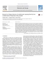
4.2.1.1 Effects of R/h ratio Figures 4 and 5 describe the effects of the ratio R/ h on dynamical buckling loads
of imperfect stiffened three-layered convex and concave shell, respectively, subjected axial compression load
without fluid and fully-filled with fluid. As can be seen, for convex shells the dynamical critical buckling load
of fully fluid-filled shell is greater about three times than that of the shell without fluid, while for concave shells
this is about four times greater. This means that when the shells contains fluid, the dynamic critical buckling
will increase due to the “added mass effect.” Furthermore, the amplitudes of deflection of fully-filled shells
are higher than these of shells without fluid about 2.3 times and 2.7 times for convex shell and concave shell,
respectively.
Research on dynamical buckling of imperfect stiffened three-layered toroidal shell
Fig. 4 Effect of R/ h ratio on dynamical buckling load of imperfect stiffened three-layered convex shells containing full-filled
fluid and no fluid under axial compression load
Fig. 5 Effect of R/h ratio on dynamical buckling load of imperfect stiffened three-layered concave shells containing full-filled
fluid and no fluid under axial compression load
Moreover, when the R/ h ratios increase from 400 to 600, the dynamic critical buckling loads of both shells
decrease. The dynamic critical buckling loads of convex shells are higher than those of concave shells with
the same parameters and environment. Particularly, with R/ h = 400, the dynamic critical buckling load of
the fully-filled convex shell is about pcr = 1012 tcr = 1012 0.045 = 45 GPa, while the one of the fully-filled
concave shell is about pcr = 1012 tcr = 1012 0.04 = 40 GPa.
4.2.1.2. Effects of L/a ratio Effects of the ratio L/a on the dynamic buckling load of three-layered convex and
concave shells are illustrated in Figs. 6 and 7, respectively. It is observed that when L/a ratios increase that
means the length of shells is increased; the dynamic critical buckling loads of both of shells also rise under
axial compression load. The dynamic the critical buckling loads of concave shells, however, always are lower
than those of convex shells for both cases: no fluid and fully fluid-filled. For instance, for L/a = 4 with fully
filled shells, the dynamical critical buckling load of the convex shell is around pcr = 1012 tcr = 1012 0.08 = 80
GPa, while the one of the concave shell is around pcr = 1012 tcr = 1012 0.07 = 70 GPa. Furthermore, the
amplitudes as well as the dynamic critical buckling loads of fully fluid-filled shells are always higher than
those of shells without fluid.
4.2.1.3. Effects of L/R ratio Based on Figs. 8 and 9, it can be seen that effects of the ratio L/R on the dynamic
buckling of FGM core toroidal shell segments are similar to those of L/a ratios. Outstandingly, the longer
the shells are, the higher the dynamic critical buckling loads of the shells are. There is a special thing that
D. H. Bich, D. G. Ninh
Fig. 6 Effect of L/a ratio on dynamical buckling load of imperfect stiffened three-layered convex shells containing full-filled
fluid and no fluid under axial compression load
Fig. 7 Effect of L/a ratio on dynamical buckling load of imperfect stiffened three-layered concave shells containing full-filled
fluid and no fluid under axial compression load
the amplitudes of convex shells always are lower than those of concave shells with the same parameters. This
means that the structure of convex shells works better than one of concave shells.
4.2.1.4. Effects of volume fraction k The effect of the volume fraction k on the dynamical the buckling of the
stiffened FGM core convex shell is shown in Fig. 10. The dynamical critical buckling loads of stiffened FGM
core toroidal shell segment decrease when the value of the volume fraction index increases. This property
apparently appropriates to the real characteristic of the material, since the higher value of k corresponds to a
metal-richer shell which has less stiffness than a ceramic-richer one.
4.2.1.5. Effects of imperfection Figures 11 and 12 show effects of imperfection on dynamical buckling loads
of stiffened convex and concave shells in full-filled fluid environment, respectively. As can be seen, the
imperfection has remarkable influence dynamical buckling loads of structures. For instance, the dynamical
critical buckling load of a perfect convex shell is about pcr = 1012 tcr = 1012 0.075 = 75 GPa, while the one
of an imperfect convex shell with f o = 0.1h is about pcr = 1012 tcr = 1012 0.047 = 47 GPa. This means that
one of perfect convex shell is 1.5 times higher than the one of the imperfect convex shell with f o = 0.1h. This
is similar to the structure of the concave shell.
4.2.1.6. Effects of ceramic layer The effect of the ceramic layer on the dynamic buckling of fully fluid-filled
convex shells is illustrated in Fig. 13. The dynamic critical buckling load of FGM core shells increases when the
Research on dynamical buckling of imperfect stiffened three-layered toroidal shell
Fig. 8 Effect of L/R ratio on dynamical buckling load of imperfect stiffened three-layered convex shells containing full-filled
fluid and no fluid under axial compression load
Fig. 9 Effect of L/R ratio on dynamical buckling load of imperfect stiffened three-layered concave shells containing full-filled
fluid and no fluid under axial compression load
Fig. 10 Effect of volume fraction k on dynamical buckling load of perfect and imperfect stiffened three-layered convex shells
containing full-filled fluid under axial compression load
D. H. Bich, D. G. Ninh
Fig. 11 Effect of imperfection on dynamical buckling load of imperfect stiffened three-layered convex shells containing full-filled
fluid under axial compression load
Fig. 12 Effect of imperfection on dynamical buckling load of imperfect stiffened three-layered concave shells containing full-filled
fluid under axial compression load
Fig. 13 Effect of ceramic layer on dynamical buckling load of imperfect three-layered convex shells containing full-filled fluid
under axial compression load
Research on dynamical buckling of imperfect stiffened three-layered toroidal shell
Table 2 Effects of L/R ratio and R/ h ratio on dynamical critical buckling load (GPa) of imperfect three-layered FGM convex
and concave shells under lateral pressure (movable case)
Shell
Convex shell
L/R ratio
1
2
3
Concave shell
1
2
3
Environment
R/ h ratio
No fluid
Full-filled fluid
No fluid
Full-filled fluid
No fluid
Full-filled fluid
No fluid
Full-filled fluid
No fluid
Full-filled fluid
No fluid
Full-filled fluid
200
0.3984
1.8555
0.6721
2.3487
0.7921
3.1864
0.3670
1.8400
0.5280
2.2912
0.6575
3.0568
300
0.5152
2.0337
0.7698
3.1698
0.8066
3.8011
0.4918
2.0018
0.6603
3.0441
0.7354
3.7818
400
0.6223
2.4433
0.7861
3.6658
0.8097
4.4064
0.5875
2.4198
0.7345
3.6489
0.7859
4.2854
Fig. 14 Effect of L/R on dynamical buckling load of imperfect three-layered convex shells containing fluid and no fluid under
lateral pressure (movable case)
thickness of ceramic layer increases. It means that the sandwich structures will be stiffer than FGM structures
with the same geometry parameters. Moreover, the amplitudes of sandwich structure will be lower than these
of FGM structure.
4.2.2 Case 2: Movable case with lateral pressure
4.2.2.1. Effects of R/h and L/R ratio In this section, the paper researches dynamic buckling of three-layered
toroidal shell segment under lateral pressure.
Table 2 indicates the effects of R/ h ratio and L/R ratio on the dynamic buckling of convex shell and
concave shell. Figures 14 and 15 express the effect of L/R ratio on dynamic buckling of convex and concave
shell, respectively, in two cases: fully fluid-filled and no fluid. The parameters of the shell are follows:
h = 0.01m; h c = 0.3h; h m = 0.1h; h 1 = h 2 = d1 = d2 = h/2; n 1 = n 2 = 50; a = 100h; f o = 0.1h; (m, n)
= (1, 1); ε = 0.1; q = 1012 t.
It is observed that the dynamic critical buckling loads of convex and concave shell under lateral pressure
will increase if R/ h ratios increase. Furthermore, this also happens to the regulations of L/R ratios. It means
that the longer the shells are, the higher the dynamic critical buckling loads are. On the other hand, the dynamic
critical buckling loads of convex shells are always higher than those of concave shells with the same parameters.
The dynamic critical buckling loads of full-filled shells are higher about 2.5 to 5 times than those of shells
without fluid.
4.2.2.2. Effects of fluid and volume fraction k Effect of fluid and volume fraction k on the dynamic critical
buckling load of FGM sandwich convex and concave shell subjected to lateral pressure is given in Table 3.
D. H. Bich, D. G. Ninh
Fig. 15 Effect of L/R on dynamical buckling load of imperfect three-layered concave shells containing fluid and no fluid under
lateral pressure (movable case)
Table 3 Effect of volume fraction k on dynamical critical buckling load (GPa) of imperfect three-layered FGM convex and
concave shells under lateral pressure (movable case)
Shell
Environment
k
Convex shell
No fluid
Full-filled fluid
No fluid
Full-filled fluid
0
0.3763
1.8151
0.3754
1.7654
Concave shell
0.5
0.3631
1.8140
0.3617
1.7450
1
0.3626
1.8102
0.3591
1.7357
10
0.3611
1.8099
0.3576
1.8027
∞
0.3599
1.8026
0.3571
1.7963
h = 0.01m; h c = 0.3h; h m = 0.1h; h 1 = h 2 = d1 = d2 = h/2; n 1 = n 2 = 50; a = 100h; R/ h = 300 and
− 300; L/a = 2; f o = 0.1h; (m, n) = (1, 1); ε = 0.1; q = 1012 t
Table 4 Comparison of dynamical critical buckling load (GPa) of imperfect three-layered FGM convex and concave shells under
lateral pressure in two cases without fluid
R/h
300
Loading speed
Immovable case
Movable case
Immovable case
Movable case
Immovable case
Movable case
c2 =
c2 = 1011 GPa/s
c2 = 1012 GPa/s
0.0132
0.0787
0.4173
0.0130
0.0777
0.4153
0.0129
0.0782
0.4161
0.0127
0.0763
0.4141
0.0127
0.0771
0.4153
0.0125
0.0758
0.4133
R/h
−300
c2 = 1010 GPa/s
c2 = 1011 GPa/s
c2 = 1012 GPa/s
0.0131
0.0762
0.4138
1010 GPa/s
400
500
−400
0.0129
0.0756
0.4123
0.0127
0.0758
0.4113
−500
0.0125
0.0753
0.4097
0.0125
0.0757
0.4111
0.0124
0.0752
0.4094
It is apparent that when the volume fraction index increases, this means that metal-richer volume increases,
the dynamic critical buckling loads also decrease because of the reduced stiffness of structure. Furthermore,
dynamic critical buckling loads of full-filled fluid structures are more around 5.0 times than those of structures
without fluid.
4.2.3 Case 3: Immovable case with lateral pressure
In this section, dynamic buckling loads of shells with immovable case under lateral pressure are studied.
Tables 4 and 5 describe comparison of dynamical critical buckling loads of imperfect three-layered FGM
convex and concave shells in immovable and movable case without fluid and fully-filled with fluid, respectively.
The parameters of the problem are as follows:
Research on dynamical buckling of imperfect stiffened three-layered toroidal shell
Table 5 Comparison of dynamical critical buckling load (GPa) of imperfect three-layered FGM convex and concave shells under
lateral pressure in two cases with full-filled fluid
R/ h
300
Loading speed
Immovable case
Movable case
Immovable case
Movable case
Immovable case
Movable case
c2 =
c2 = 1011 GPa/s
c2 = 1012 GPa/s
0.0635
0.3630
2.0462
0.0629
0.3614
2.0205
0.0631
0.3613
1.9901
0.0625
0.3597
1.9852
0.0627
0.3605
1.9887
0.0625
0.3589
1.9801
R/ h
−300
c2 = 1010 GPa/s
c2 = 1011 GPa/s
c2 = 1012 GPa/s
0.0628
0.3591
2.0383
1010 GPa/s
400
500
−400
0.0625
0.3578
2.0147
0.0626
0.3553
1.9871
−500
0.0624
0.3539
1.9832
0.0625
0.3551
1.9862
0.0621
0.3537
1.9772
h = 0.01m; h c = 0.3h; h m = 0.1h; h 1 = h 2 = d1 = d2 = h/2; k = 1; n 1 = n 2 = 50; a = 200h; L = 2a; f o =
0.1h; (m, n) = (1, 7); ε = 0.1; q = c2 t
There are three pivotal comments in the two Tables. Firstly, the dynamic critical buckling loads of both
convex and concave shell in the immovable case are higher than those of shells in the movable case. This is
explained due to more stiffness of immovable condition. Secondly, the dynamic critical buckling load increases
approximately 6.0 times when the loading speed rises 10.0 times. Finally, the regulations of characteristics
about the geometry and the environment such as R/ h ratios, convex and concave shell and no fluid and fully
fluid-filled are similar to the above-analyzed studies.
5 Conclusions
The nonlinear dynamical buckling of imperfect eccentrically stiffened three-layered toroidal shell segments
fully-filled with fluid is investigated using the classical shell theory. The Galerkin method, Volmir’s assumption
and a numerical method using fourth-order Runge–Kutta are computerized for dynamic analysis of shells.
Effects of geometrical and material parameters, imperfection and fluid on the nonlinear dynamical buckling
behavior of shells are illustrated in the obtained results. Some significant conclusions are obtained as follows:
– The results obtained in this paper are compared with the results of other authors to validate.
– The fluid remarkably influences the dynamic buckling loads of the FGM sandwich toroidal shell segment.
Particularly, it makes the dynamical critical buckling loads increase many times more than without fluid.
– Geometrical ratios, imperfection, ceramic and metal layer considerably affect the dynamical buckling
behavior of shells. Furthermore, the dynamic critical buckling loads of a concave shell are always lower
than those of a convex shell with the same parameters. It means that the carrying capacity of a convex shell
is better than that of a concave shell.
– The dynamical critical buckling pressure loads of shells in the immovable case are always greater than
those of shells in the movable case.
Acknowledgments This work was supported by The scientific research Project of Hanoi University of Science and Technology
under Grant number T2016-PC-056. The authors are grateful for this support.
References
1. Chen, W.Q., Bian, Z.G., Ding, H.J.: Three-dimensional vibration analysis of fluid-filled orthotropic FGM cylindrical shells.
Int. J. Mech. Sci. 46, 159–171 (2004)
2. Khorshidi, K., Bakhsheshy, A.: Free vibration analysis of a functionally graded rectangular plate in contact with a bounded
fluid. Acta Mech. 226, 3401–3423 (2015)
3. Sheng, G.G., Wang, X.: Thermomechanical vibration analysis of a functionally graded shell with flowing fluid. Eur. J. Mech.
A Solids 27, 1075–1087 (2008)
4. Bochkarev, S.A., Matveenko, V.P.: Numerical analysis of stability of a stationary or rotating circular cylindrical shell containing axially flowing and rotating fluid. Int. J. Mech. Sci. 68, 258–269 (2013)
5. Ross, C.T.F., Koster, P., Little, A.P.F., Tewkesbury, G.: Vibration of a thin-walled prolate dome under external water pressure.
Ocean Eng. 34, 560–575 (2007)
D. H. Bich, D. G. Ninh
6. Prado, Z., Goncalves, P.B., Paidoussis, M.P.: Non-linear vibrations and instabilities of orthotropic cylindrical shells with
internal flowing fluid. Int. J. Mech. Sci. 52, 1437–1457 (2010)
7. Zhu, X., Ye, W.B., Li, T.Y., Chen, C.: The elastic critical pressure prediction of submerged cylindrical shell using wave
propagation method. Ocean Eng. 58, 22–26 (2013)
8. Sburlati, R.: An axisymmetric elastic analysis for circular sandwich panels with functionally graded cores. Compos. Part B
Eng. 43, 1039–1044 (2012)
9. Sofiyev, A.H., Kuruoglu, N.: Dynamic instability of three-layered cylindrical shells containing an FGM interlayer. Thin
Walled Struct. 93, 10–21 (2015)
10. Sofiyev, A.H., Hui, D., Najafov, A.M., Turkaslan, S., Dorofeyskaya, N., Yuan, G.Q.: Influences of shear stresses and rotary
inertia on the vibration of functionally graded coated sandwich cylindrical shells resting on the Pasternak elastic foundation.
J. Sandw. Struct. Mater. (2015). doi:10.1177/1099636215594560
11. Alibeigloo, A., Alizadeh, M.: Static and free vibration analyses of functionally graded sandwich plates using state space
differential quadrature method. Eur. J. Mech. A Solids 54, 252–266 (2015)
12. Taibi, F.Z., Benyoucef, S., Tounsi, A., Bouiadjra, R.B., Bedia, E.A.A., Mahmoud, S.R.: A simple shear deformation theory
for thermo-mechanical behavior of functionally graded sandwich plates on elastic foundation. J. Sandw. Struct. Mater. 17,
99–129 (2015)
13. Xia, X., Shen, H.S.: Vibration of post-buckled sandwich plates with FGM face sheets in a thermal environment. J. Sound
Vib. 314, 254–274 (2008)
14. Khalili, S.M.R., Mohammadi, Y.: Free vibration analysis of sandwich plates with functionally graded face sheets and
temperature-dependent material properties: A new approach. Eur. J. Mech. A Solids 35, 61–74 (2012)
15. Wang, Z., Shen, H.S.: Nonlinear dynamic response of sandwich plates with FGM face sheets resting on elastic foundations
in thermal environments. Ocean Eng. 57, 99–110 (2013)
16. Shariyat, M.: Dynamic thermal buckling of suddenly heated temperature-dependent FGM cylindrical shells, under combined
axial compression and external pressure. Int. J. Solids Struct. 45, 2598–2612 (2008)
17. Shariyat, M.: Dynamic buckling of suddenly loaded imperfect hybrid FGM cylindrical shells with temperature-dependent
material properties under thermo-electro-mechanical loads. Int. J. Mech. Sci. 50, 1561–1571 (2008)
18. Huang, H., Han, Q.: Nonlinear dynamic buckling of functionally graded cylindrical shells subjected to time-dependent axial
load. Compos. Struct. 92, 593–598 (2010)
19. Huang, H., Han, Q.: Research on nonlinear postbuckling of functionally graded cylindrical shells under radial loads. Compos.
Struct. 92, 1352–1357 (2010)
20. Bich, D.H., Dung, D.V., Nam, V.H., Phuong, N.T.: Nonlinear static and dynamic buckling analysis of imperfect eccentrically
stiffened functionally graded circular cylindrical thin shells under axial compression. Int. J. Mech. Sci. 74, 190–200 (2013)
21. Bich, D.H., Dung, D.V., Hoa, L.K.: Nonlinear static and dynamic buckling analysis of functionally graded shallow spherical
shells including temperature effects. Compos. Struct. 94, 2952–2960 (2012)
22. Sofiyev, A.H., Kuruoglu, N.: Domains of dynamic instability of FGM conical shells under time dependent periodic loads.
Compos. Struct. 136, 139–148 (2016)
23. Sofiyev, A.H.: On the dynamic buckling of truncated conical shells with functionally graded coatings subject to a time
dependent axial load in the large deformation. Compos. Part B Eng. 58, 524–533 (2014)
24. Duc, N.D., Quan, T.Q., Luat, V.D.: Nonlinear dynamic analysis and vibration of shear deformable piezoelectric FGM double
curved shallow shells under damping-thermo-electro-mechanical loads. Compos. Struct. 125, 29–40 (2015)
25. Zhang, J., Li, S.: Dynamic buckling of FGM truncated conical shells subjected to non-uniform normal impact load. Compos.
Struct. 92, 2979–2983 (2010)
26. McElman, J.A.: Eccentrically stiffened shallow shells of double curvature. NASA Technical note; D-3826 (1967)
27. Hutchinson, J.W.: Initial post-buckling behavior of toroidal shell segments. J. Solid Struct. 3, 97–115 (1967)
28. Stein, M., McElman, J.A.: Buckling of segments of toroidal shells. AIAA J. 3, 1704–1709 (1965)
29. Bich, D.H., Ninh, D.G., Thinh, T.I.: Buckling analysis of eccentrically stiffened functionally graded toroidal shell segments
under mechanical load. J. Eng. Mech. ASCE 142, 0405054-1–0405054-10 (2015)
30. Bich, D.H., Ninh, D.G.: Post-buckling of sigmoid-functionally graded material toroidal shell segment surrounded by an
elastic foundation under thermomechanical loads. Compos. Struct. 138, 253–263 (2016)
31. Bich, D.H., Ninh, D.G., Thinh, T.I.: Nonlinear buckling analysis of FGM toroidal shell segments filled inside by an elastic
medium under external pressure loads including temperature effects. Composite: Part B. Engineering 87, 75–91 (2016)
32. Ninh, D.G., Bich, D.H., Kien, B.H.: Torsional buckling and post-buckling behaviors of eccentrically stiffened functionally
graded toroidal shell segments surrounded by an elastic medium. Acta Mech. 226, 3501–3519 (2015)
33. Ninh, D.G., Bich, D.H.: Nonlinear buckling of eccentrically stiffened functionally graded toroidal shell segments under
torsional load surrounded by elastic foundation in thermal environment. Mech. Res. Commun. 72, 1–15 (2016)
34. Ninh, D.G., Bich, D.H.: Nonlinear thermal vibration of eccentrically stiffened ceramic-FGM-metal layer toroidal shell
segments surrounded by elastic foundation. Thin Walled Struct. 104, 198–210 (2016)
35. Brush, D.O., Almorth, B.O.: Buckling of Bars, Plates and Shells. Mc. Graw-Hill, New York (1975)
36. Volmir, A.S.: Nonlinear Dynamic of Plates and Shells, science edition (1972) (in Russian)
37. Budiansky, B., Roth, R.S.: Axisymmetric dynamic buckling of clamped shallow spherical shells. NASA Technical Note
D-510, pp. 597–609 (1962)