Charging System Diagnosis, Testing, and Repair
Bạn đang xem bản rút gọn của tài liệu. Xem và tải ngay bản đầy đủ của tài liệu tại đây (2.86 MB, 64 trang )
by
Russell Krick
Publisher
The Goodheart-Willcox Co., Inc.
Tinley Park, Illinois
© Goodheart-Willcox Co., Inc.
Permission granted to reproduce for educational use only
© Goodheart-Willcox Co., Inc.
Permission granted to reproduce for educational use only
Charging system diagnosis
Charging system precautions
Charging system tests
Alternator service
Regulator service
© Goodheart-Willcox Co., Inc.
Permission granted to reproduce for educational use only
© Goodheart-Willcox Co., Inc.
Permission granted to reproduce for educational use only
Common Symptoms
Dead battery
causes slow or no cranking
Overcharged battery
signaled by low battery electrolyte
Abnormal noise
grinding, squealing, and buzzing
Indicator light illuminated
© Goodheart-Willcox Co., Inc.
Permission granted to reproduce for educational use only
Visual Inspection
Inspect for:
loose battery cables
discharged battery
corroded terminals
low electrolyte
damaged battery case
belt tension and condition
wiring condition
© Goodheart-Willcox Co., Inc.
Permission granted to reproduce for educational use only
Common
Problems
© Goodheart-Willcox Co., Inc.
Permission granted to reproduce for educational use only
Belt Tension
1/2" deflection
© Goodheart-Willcox Co., Inc.
Belt tension gauge
Permission granted to reproduce for educational use only
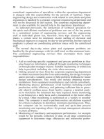
Belt
Problems
Inspect belts for these
kinds of problems
© Goodheart-Willcox Co., Inc.
Permission granted to reproduce for educational use only
Belt Adjustment
Loosen the bolts and
pry on a thick area of
the end frame
© Goodheart-Willcox Co., Inc.
Permission granted to reproduce for educational use only
Scanning
Vehicles with self-diagnostic systems
allow you to connect a scan tool for
diagnostics
Scan for diagnostic trouble codes
Display charging data:
voltage
battery temperature
© Goodheart-Willcox Co., Inc.
Permission granted to reproduce for educational use only
Disconnect the battery before servicing
Never reverse the polarity
Do not operate the alternator with the
output wire disconnected
Never short or ground the terminals
unless instructed to do so by the shop
manual
Never polarize an alternator
© Goodheart-Willcox Co., Inc.
Permission granted to reproduce for educational use only
Output test
Regulator voltage test
Regulator bypass test
Scope testing
Circuit resistance tests
Voltmeter testing
© Goodheart-Willcox Co., Inc.
Permission granted to reproduce for educational use only
Output Test
Measures system current and voltage
under maximum load
Use a load tester with a voltmeter and
an ammeter
© Goodheart-Willcox Co., Inc.
Permission granted to reproduce for educational use only
Equipment Connection
Connect the
voltmeter leads
across battery and
the inductive pickup
on the battery’s
ground cable
© Goodheart-Willcox Co., Inc.
Permission granted to reproduce for educational use only
Output Test Procedure
Ignition on, record ammeter reading
Start engine, operate at 2000 rpm
Load battery until ammeter reads
specified output current
Do not let voltage fall below 12 volts
© Goodheart-Willcox Co., Inc.
Permission granted to reproduce for educational use only
Output Test Results
Add the two amperage readings
together
key on, engine off + engine running
The result is the alternator output in
amperes
Compare to specifications
© Goodheart-Willcox Co., Inc.
Permission granted to reproduce for educational use only
Regulator Voltage Test
Checks the regulator calibration
Connect the load tester
With the load control off, run the engine
at 2000 rpm
Compare the battery voltage to
specifications
Most are in a range of 13.5–14.5 volts
Some regulators are adjustable
© Goodheart-Willcox Co., Inc.
Permission granted to reproduce for educational use only
Regulator Bypass Test
Performed if the output test has failed
The regulator is removed from the field
circuit, applying full voltage to the field
Follow the shop manual procedures
the insulated screw head or test tab may
be grounded
a jumper wire may be installed between
the alternator’s battery and field terminals
© Goodheart-Willcox Co., Inc.
Permission granted to reproduce for educational use only
Regulator Bypass Test
Shorting the tab
should make this
alternator produce the
maximum output
© Goodheart-Willcox Co., Inc.
Permission granted to reproduce for educational use only
Regulator Bypass Test
Two methods of bypassing the regulator
© Goodheart-Willcox Co., Inc.
Permission granted to reproduce for educational use only
Regulator Bypass Test
Results
If the charging voltage and current
increase to normal when the regulator
is bypassed, the regulator is bad
If the output remains the same, the
alternator is bad or there is a wiring
problem
© Goodheart-Willcox Co., Inc.
Permission granted to reproduce for educational use only
Charging System
Scope Testing
An oscilloscope may be used to
diagnose problems with the alternator
or field control
A scope may be connected between
the alternator output terminal or field
terminal and ground
© Goodheart-Willcox Co., Inc.
Permission granted to reproduce for educational use only
Hand-Held
Oscilloscope
Note the
connections and
the output trace
© Goodheart-Willcox Co., Inc.
Permission granted to reproduce for educational use only
Normal Output
Small, regularly spaced, even ripples
© Goodheart-Willcox Co., Inc.
Permission granted to reproduce for educational use only