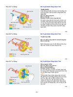
HỘP SỐ TỰ ĐỘNG (Automatic transmission)
Bạn đang xem bản rút gọn của tài liệu. Xem và tải ngay bản đầy đủ của tài liệu tại đây (1.02 MB, 16 trang )
AUTOMATIC GEAR
TRANSMISSION
By :
Rohit.S.Kumar (14MD16)
CONTENTS
•
•
•
•
•
•
Introduction
Classification
Automatic transmission using planetary gea
Continuously variable transmission
Conclusion
References
INTRODUCTION
• Device which changes gear ratios automatically
• Deliver maximum efficiency
• Easier to drive because they do not have a clutch pedal or
gearshift lever
• Automatic transmissions contain mechanical systems, hydraulic
systems, electrical systems and computer controls, all working
together in perfect harmony.
CLASSIFICATION
Automatic transmissions
using planetary gears
Continuously
variable transmission(cvt)
AUTOMATIC TRANSMISSIONS USING
PLANETARY GEARS
Components :
• Planetary Gear System
• Torque Converter
• Hydraulic System
• Governor
• Computer Controls
HOW PLANETARY GEARS WORK
• A gear set in which all of the gears are grouped around each other like
the planets around the sun.
• The central gear is called sun gear. In mesh with it is a circular
grouping of gears, called planet gears, mounted on a rotating carrier.
• By holding any one of the three gear elements motionless, different
ratios can be produced between the other two. Planetary gear sets are
common in automatic transmissions.
Input
Output
Stationary
Calculation
Gear Ratio
A
Sun (S)
Planet Carrier (C)
Ring (R)
1 + R/S
3.4:1
B
Planet Carrier (C)
Ring (R)
Sun (S)
1 / (1 + S/R)
0.71:1
C
Sun (S)
Ring (R)
Planet Carrier (C)
-R/S
-2.4:1
TORQUE CONVERTOR
•
•
•
a.
b.
c.
Takes the place of the clutch found on standard shift
vehicles
It uses oil or transmission fluid to transmit power
Torque converter can be divided into 3
main members:
Pump/impeller: It is the driving member and rotates
with the engine.
Turbine: The impeller vanes pick up fluid in the
converter housing and direct it toward the turbine.
Stator: Fluid flow drives the turbine, and the turbine
rotates and turns the transmission input shaft.
TORQUE CONVERTOR
THE HYDRAULIC SYSTEM
• Complex maze of passages and tubes that sends transmission
fluid under pressure to all parts of the transmission
and torque converter.
• It works with some components:
•
Oil pump
•
Valve body
•
Shift valves
Oil pump: The oil is then sent, under pressure to the pressure
regulator, the valve body and the rest of the components, as
required.
VALVE BODY
• The brain of the automatic
transmission
• Contains a maze of channels and
passages that direct hydraulic
fluid to the numerous valves
• These valves activate the
appropriate clutch pack or band
servo to smoothly shift to the
appropriate gear for each driving
situation.
Shift Valves
• Supply hydraulic pressure to
the clutches and bands to
engage each gear
• Determines when to shift from
one gear to the next
• The 1 to 2 shift valves determines
when to shift from first to second
gear.
Continuously variable transmission
• A continuosly variable transmission is a transmission
which can change steplessly through an infinite number
of effective gear ratios between maximum and minimum
values.
• CVTs operate smoothly since there are no gear changes
which cause sudden jerks .
• There are 25% fewer moving parts to a CVT
transmission
COMPUTER CONTROLLS
•
•
•
•
Detect such things as throttle position, vehicle speed,
engine speed, engine load etc. To control exact shift
points .
Downshift automatically when going downhill, to
control speed and reduce wear on the brakes.
Up shift when braking on a slippery surface to reduce
the braking torque applied by the engine.
Inhibit the up shift when going into a turn on a winding
road.
CONCLUSION
Automatic transmissions contain mechanical systems, hydraulic
systems, electrical systems and computer controls, all working
together in perfect harmony
REFERENCES
www.drivetrain.com
www.sciencedirect.com
www.scribd.co
www.youtube.com
/>automatic transmission.html
Google , Wikipedia.