The analysis of the influence of TiO2 content in the structure of the PILCs.
Bạn đang xem bản rút gọn của tài liệu. Xem và tải ngay bản đầy đủ của tài liệu tại đây (964.78 KB, 48 trang )
1
ACKNOWLEDGEMENT
In order to complete this thesis, I have been trying a lot and the thesis would
not have been possible without the time, support and dedication of many people.
At first, I would like to send my sincere thanks to Associated. Professor
Pham Xuan Nui PhD who is dedicated to guide me during the time, gave me a lot of
knowledge about a new scope when I started to conduct this thesis. During the
implementation, my teacher always directed, instructed and made suggestion so that
I can complete this thesis.
I sincerely thank Advanced Program, Departure of Oil Refining and
Petrochemistry, Hanoi University of Mining and Geology for providing facilities to
study, optimal laboratory conditions, which help me complete this thesis.
Finally, I would like to say thanks to my dear parents for supporting me spiritually
throughout writing this thesis and my life in general.
Ha Noi, June 5th, 2017
Student
Nguyen Huy Thanh
2
Table of Contents
3
List of Tables
Table 1.1. European emission standards of sulfur contents ......................................9
Table 1.2. Results of desulfurizaion in diesel fuel....................................................11
Table 4.1. The content of components in TiO2/Mont and CuO-TiO2/Mont............38
Table 4.2. Band gap energy of catalyst material TiO 2/Mont and CuOTiO2/Mont.................................................................................................................39
Table 4.3. Thiophene conversion with 2 different kinds of catalyst samples:
TiO2/Mont and CuO-TiO2/Mont...............................................................................43
List of Figures
Figure 1.1. General mechanism of hecterogeneous photocatalysis.........................14
Figure 1.2. Operation of semiconducted particle being excited by light................16
Figure 1.3. Crystal structure of Titanium Dioxide....................................................17
Figure 1.4. Energy diagram of Anatase and Rutile...................................................20
Figure 1.5. Decomposition process of organic compound using TiO2
photocatalyst.............................................................................................................22
Figure 1.6. Diagram for synthesis Ti(x)C16(y)-Mont...............................................24
Figure 2.1. XRD diagram of Bentonite and Momorillonite (after purifying)........27
Figure 2.2. Preparation of Na-Montmorillonite.......................................................28
Figure 2.3. Experimental process for modifying montmorillonite..........................29
Figure 2.4. The Sol-gel was added to the mixture drop by drop..............................30
Figure 2.5. Inspecting photoreactivity of TiO2 and CuO-TiO2 Mont samples.......30
Figure 4.1. XRD diagram of TiO2/Mont (a) and CuO-TiO2/Mont (b).....................36
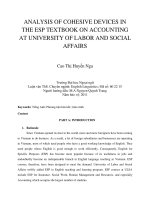
Figure 2.3: Modification process of Titanium dioxide on Monmorillonite
4
Figure 4.2. The EDX spectroscopy of (a) TiO2/Mont and (b) CuO-TiO2/Mont
sample.......................................................................................................................37
Figure 4.3. UV-Vis result of (a) TiO2-Mont, (b) CuO-TiO2/Mont...........................38
Figure 4.4. Standard curve result of Thiophene sample model with standard curve
equation Spic = 66037,48 + 53521,98 x CThiophene......................................................41
Figure 4.5. The conversion result of thiophene with TiO2/Mont catalyst sample after
180 minutes...............................................................................................................41
Figure 4.6. The conversion result of thiophene with CuO-TiO 2/Mont catalyst sample
after 180 minutes..........................................................................................42
Figure 4.7. Thiophene conversion with 2 different kinds of catalyst samples:
TiO2/Mont and CuO-TiO2/Mont...............................................................................42
5
Abbreviations
ULDS : Ulltra-low-sulfur-diesel
VB
: Valance Band
CB
: Conduction Band
BG
: Band Gap
SC
: Semiconductor Surface
Mont
: Montmorillonite
CTABr : Cetyltrimethylammonium bromides
6
INTRODUCTION
Nowadays, environmental pollution is becoming an urgent issue. European
Standards for fuels now are more and more restrictive. Sulfur-containing organic
compounds are potential pollutants present mainly in fuel oils which are difficult to
be removed. Traditional methods used for desulfurization such as
hydrodesulfurization (HDS) shows out ineffectively in deep desulfurization (for
sulfur-containing heterocyclic compounds) and costly. One of the new materials that
is catching the attention of scientists is TiO 2 photocatalyst. With the presence of
TiO2 and ultraviolet irradiation, researchers found that organic compounds,
pollutants are easily disintegrated [1]. This special ability of TiO2 has been applied
in water purification, air and disinfection technologies. Many toxic and hazardous
compounds are efficiently degraded by heterogeneous photocatalyst. The use of
titanium dioxide as photocatalyst for air and water treatment is well documented as
well as the fundamental mechanisms of the process [2]. The main primary step is
the adsorption of the substrate on the support. Thus, efforts have been carried out
on the synthesis of new materials having high specific surface area, low particles
size with the highest expected photoreactivity. Supported TiO2 on different minerals
or TiO2 thin films appeared as solutions to overcome the recovery problem and also
to enlarge the application fields [3]. Mesoporous materials which can be easily
separated from the treated effluent, have been synthesized, and demonstrated their
feasibility for photocatalytic treatment of fuel. They are mainly based on clay
minerals, zeolites, silica or activated carbons. Among them, pillared clays (PILCs),
constitute a group of mesoporous materials. Pillared interlayered clays (PILCs)
form a well-known family of microporous and mesoporous materials [4]. They are
prepared by multi-step molecular engineering processes. The insertion of pillaring
agents (organic, organometallic, or inorganic complexes) expands the interlayer
spacing leading to a two-dimensional channel system with porous structures
comparable to those of zeolites [5]. After the calcination process, the inserted
cationic polymers yield rigid and are thermally stable leading to oxide species in
form of pillars, which hold (separated) the clay layers separated and prevent their
collapse at high temperatures. Thus, PILCs may be viewed as clay layers separated
by metallic oxide based pillars (alumina, titania, zirconia, iron oxide, etc.), or
alternatively, as dispersed nanometric oxide particles which aggregation is hindered
7
by the presence of the clay layers [4]. The main objective in the formation of PILCs
is to achieve as basal spacing as large as possible contributing to the development of
higher surface area and porous volume. The addition of TiO 2 to the PILCs has been
previously studied.
For this reason, the main objectives of this thesis are the analysis of the
influence of TiO2 content in the structure of the PILCs. This thesis describes
synthesis and characterization of montmorillonite based porous clay heterostructure
with modified titanium dioxide in their pillars. Likewise this thesis discusses the
role of CuO located in the pillars and its effect in oxidative desulfurizaion leading to
an advantageous way to design functional materials with photocatalytic and
adsorbent applications for deep desulfurizaion in fuel.
Thesis objects:
• Modification of bentonite by titanium dioxide
• Doping copper oxide on titanium dioxide
• Investigating photocatalytic activity of synthesised samples
8
PART 1. OVERVIEW
1.1. Euro standards for sulfur content
Emissions of SOx, NOx, ... from the combustion of organic compounds which
contain heteroatoms as sulfur, nitrogen in fuel has become an environmental issue
over the world. Because these emission gases are one of the main reason of acid
rain, Global warming-up and atmospheric pollution [1]. To minimize the amount of
SOx emissions, many countries in the world have put strict requirements on the
sulfur content in fuel.The amount of sulfur contained in the material. Example,
sulfur content in diesel must be reduced from 500ppmw to less than 15ppmw for
diesel and from 300ppmw to less than 30 ppmw for gasoline. Therefore, Deepdesulfurizaion method are increasingly interested in, recently.
Table1.1. European emission standards of sulfur contents [6]
Name
n/a
EU
Directive
-
CEN Standard
Implementation
Date
Sulfur Limit (ppm)
EN
(d)
EN
(g)
October, 1994
2000
Euro 2 93/12/EEC
Euro 3 93/12/EEC
Euro 4 98/70/EC
Euro 5
2003/17/E
C
EN
(d)
EN
(g)
EN
(d)
EN
(g)
590:1993
228:1993
October, 1996
590:1999
228:1999
500 (diesel)
January, 2000
350
(diesel)
150 (gasoline)
January, 2005
50*
January, 2009
10, 10**
590:2004
228:2004
EN 590:2009
Note:
* 10ppm fuel must be available
** nonroad fuels limit
1.2. Hydrodesulfurization
Currently, in our Country, the method is mainly used to remove sulfur out of
liquid fuel is hydrodesulphurization process (HDS) using metal - sulfide catalyst
carried on Al2O3-support.
9
Chemical theory [3] of Sulfur elimination reactions: Mercaptan, sulfur and
di-sulfur compounds gently react to form aromatic and saturated compound
corresponding. Sulfur element which is linked in aromatic ring, such as thiophene is
so much harder to eliminate. All of these reactions are exothermic reactions, they
create hydro sulfur and consume hydrogen.
Example:
-
Mercaptan compound
R - SH + H2 → R - H + H2S
-
Sulfur-containing heterocyclic compounds
R – S – R’ + 2 H2 → R – H +R’ – H + H2S
+ 2 H2 → C4H10 + H2S
S
Thiolane
+ 4 H2 → C4 H10 + H2S
S
Thiophene
+ 5 H2S →
S
+
H2S
Benzylcyclohexane
Dibenzothiophene
After HDS process, sulfur is separated from sulfur-containing compounds,
reducing the amount of sulfur in diesel fuel down to allowed level about 500 ppm.
Therefore, HDS process is applied to desulfurization of compounds such as
mercaptan, thiophene, disulfur, benzothiophene... which are contained in crude oil
and its product. Catalysts which are used for this process are normally metals such
as Co, Mo, Ni-Mo supported on solid acid. Nowadays, for deep desulfurization in
compounds which have high molecular weight and aromatic compounds, high
active catalysts are used such as: CoMo/Al 2O3, CoMoP/Al2O3, GaCr/HZSM-5 or a
mixture of CoMoP/Al2O3 + GaCr/HZSM-5.
10
Diesel fuel contains a lot of hardly reduced sulfur-containing compounds
because they are in heavy fractions and have high boiling temperature. Normally,
the amount of sulfur-containing compounds in fuel is from 9,000 to 2,000 ppm
including compounds contain sulfur which are easy and difficult to eliminate. The
productivity of desulfurization in diesel fuel using CoMoP/Al 2O3 catalyst is given
in Table 1.2.
Table 1.2. Results of desulfurizaion in diesel fuel
Temperature (K)
Sulfur content in products Desulphurization
(ppm)
(%)
590
610
630
640
1190
680
170
50
efficiency
87
92
98
99
* Disadvantages:
HDS must be implemented at high temperature and pressure condition
requiring long catalyst ‘s life cycle and high activity for deep sulfurizaiotn.
Especially, this process consume a lot of energy considerably but still not desulfur
deeply for some common compounds such as dibenzothiophene (DBT), especially
for dimetyldibenzothiophen (4.6-DMDBT) so that the sulfur content in fuel
remains high at about 500 ppm. The above conditions are also leading to high cost
of the products. Therefore, deep desulfurization without using hydrogen and harsh
conditions have been developed to overcome the disadvantages of HDS process.
Due to that, sulfur content in fuel can reduced below 10 ppm.
1.3 Oxidative desulfurization
Oxidative desulfurization is not a new concept and has been discussed for
several years in previous publications.The advantage that oxidative desulfurization
has over conventional to HDS is that the difficult-to-desulfurize, sufur-containing
heterocyclic compounds such as dibenzothiophenes (DBT) are easily oxidized at
low temperature and pressure conditions to form the corresponding sulfones. This
overall process is demonstrated as below. The oxidant can be supplied by either
hydrogen peroxide/peracid sor organic peroxide [4]. Note that there is no hydrogen
consumed in this reaction. The sulfones are highly polar compounds and are easily
11
separated from the diesel product by either extraction or adsorption.For example,
dibenzothiophene oxidation process:
This oxidation chemistry is complementary to hydrotreating, as other sulfur
compounds such as disulfides are easy to hydrodesulfurize, but oxidize slowly. For
this reason, oxidative desulfurization is best utilized as a second stage after an
existing HDS unit, taking a low sulfur diesel (~500 ppm) down to ULSD (<10 ppm)
levels. In this situation, the diesel product has been depleted of difficult-to-oxidize
sulfur species and has a high concentration of the more refractory DBT constituents.
In oxidative desulfurization (ODS) process the sulfur species like dibenzotiophene
are usually transformed into the corresponding sulfoxide and sulfone species. In
order to finally obtain a deeply desulfurized product, the sulfone species should
then be removed in a second step by extraction or adsorption.
Process of oxidative desulfurization has several advantages over HDS. ODS
can be performed under mild conditions, atmospheric pressure and temperatures till
100°C higher reactivity of aromatic compounds and no use of hydrogen. Also, some
disadvantages of ODS processes can be listed; waste management of sulfone
compounds, rise in operation cost with the increase in the feed sulfur content, some
decrease of oil yield in case that extraction is applied to the sulfone separation.
1.4. Comparations of oxidative desulfuriation to hydrodesulfurization
The HDS method is very effective at removing compounds that contains
sulfur, including saturated organic compounds and aromatics. Nevertheless, with
hectero-aromatic compounds which contain sulfur such as Dibenzothiophene
(DBT), Benzothiophene (BT),... and their derivatives, this method is not efficient.
Otherwise, this method has also got restricts because it is always carried out at high
pressure and temperature conditions, at about 300-340 oC and 20-100 atm, consume
a lot of energy, and large amounts of hydrogen.With the above disadvantages of the
HDS method, the development of a new method to eliminate sulfur significantly is
very necessary. There are some alternatives in using conventional hydrotreating
technology. Recently, some methods for deep desulfurations, those are being
catched attention recently are: Oxidative desulfuration (ODS), biodesulfurization,
12
extraction using ionic liquid,... Among them, the ODS method which uses suitable
catalysts along with oxidative agent as hydroperoxide is very promising one with
several advantages comparing to HDS such as: processes can be conducted at low
presure and temperature conditions, no need for using hydrogen, capability in
eliminating hetero-aromatic compounds more easilier.
1.5. Photocatalytic oxidation desulfurization
1.5.1. General
Traditionally, ODS operates at temperatures between 60 and 80 oC [5,7]. At
these temperatures, the oxidation of desired fuel constituents, such as alkenes
and aromatics, can occur, which consumes part of the oxidant and decreases
the overall octane rating of the fuel [8]. Unlike ODS, photocatalytic oxidative
desulfurization (PODS) can be conducted at ambient temperature and
atmospheric pressure with high product selectivity. PODS is essentially an
advanced version of ODS with a photocatalyst and UV light irradiation that
are used to increase the oxidation rate. It is a desirable process because of
its low operating costs and the potential for a free source of radiation
(natural sunlight) [8]. PODS is characterized by three phases: oil, solvent and
catalyst (solid). Thiophene molecules in the oil phase are oxidized at the
catalyst surface increasing the molecular polarity, thus causing extraction into
the solvent phase (polar) [8]. To increase the oxidation of thiophenes,
oxidants are generally added to increase the concentration of hydroxyl
radicals, subsequently increasing the sulfone production rate. Pure oxygen and
air have also been reported as successful oxidants for the oxidation process,
with overall desulfurization levels of 98% being reported for 5 h trials [8].
The investigation into photocatalyst structures and their compositions has
received much interesting in the recent years [8]. Li et al. reported a mixedphase Fe2O3 catalyst prepared by solution combustion method that gave 92.3%
sulfur removal of DBT in n-octane using air flow and simulated sunlight.
Wang et al. prepared TiO2 in ionic liquid via microwave radiation for PODS
and achieved 98.2% of DBT removal from model oil after 10 h UV
irradiation [9]. More complicated photocatalysts structures such as anatase
nanocomposite polyoxometalate (Bu4N)7H3[P2W118Cd 4(Br)2O68]-TiO2 [10] and
titanium silicalite-1 [11] were also reported to be able to increase the overall
sulfur removal efficiency. PODS using advanced catalytic material, such as
13
those mentioned above, appear to be a promising method for deep
desulfurization; nonetheless, the complexity in the synthesis of these
photocatalysts and their costs make commercialization and scaling - up
difficult. Therefore, PODS using simple reagent is still considered the best
approach from industrial perspective. However, systematic evaluation on the
optimum reaction conditions for PODS and the effect of the presence of
multiple thiophenes are still insufficient. In this study, TiO 2 was used as the
photocatalyst, and the effects of catalyst loading, pH, temperature, the oxidant
dose (H2O2) and solvent use were investigated. Thiophen were used as model
aromatic sulfur compounds, as these compounds are not easily treated using
HDS. The reaction rate constants were calculated for the reactions of Thiophene.
The effect of thiophene on the overall sulfur removal was also investigated. To
remove any matrix effects that may be experienced by the application of real
fuel, acetonitrile was used as solvent for model oil.
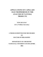
Figure 1.1. General mechanism of hecterogeneous photocatalysis
The photocatalytic process is based on the following basic principle: When
the semiconductor particle is illuminated by light sources having a greater energy
than the Band Gap, electrons in the Valence Band are excited and having enough
energy to occupy up on empty spaces in the Conduction Band, leaving vacancies in
the Valence Band. These charged particles will move to the surface of the
semiconductor particles and participate in reduction/oxidation reactions with
adsorbed matters on the surface of the semiconductor particles. However, due to
lower energy levels in the Valence Band, electrons then tend to jump back into the
Valence Band to recombine with vacancies, along with releasing of energy in form
of photons or heat.
14
1.5.2. Fundamental of photocatalytic process
Photocatalytic processes only occur with light radiation of sufficient light
energy to break chemical bonds in materials. In case of smaller light radiation
energy than chemical bond energies, the photocatalytic processes only occur with
the presence of photocatalyst. Photocatalyst contains photosensitives that has the
effect of accelerating speed of chemical reactions.
In the photocatalytic oxidation reactions with no photocatalyst, most of
hydrocarbons are oxidized slowly. Photocatalyst has got an effect of reducing the
activation energy of reactions. In the processes of light irradiation, the catalyst
often creates particles which is capable of strong oxidation and reduction. A
hecterogeneous catalytic system contains semiconductor particles play the role as
photocatalysis. When these particles are radiated, they will be in excited states.
These states will create next states such as reduction/oxidation reactions and
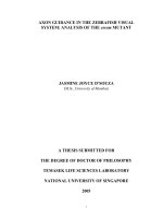
molecular changing. Figure 1.2 is the mechanism diagram of photocatalytic
reactions. The electron structure is determined by Valance Band (VB) and
Conductive Band (CB). Semiconductors (such as ZnO, TiO2, Fe2O3) can be used as
sensitive factor for reduction/oxidation reaction with photocatalytic sources. The
difference in energy level between the lowest enegy level of CB and the highest
energy level of VB is called as band gab energy E g . It corresponds to the minimum
energy of light needed to make materials become conductive.
Subtances contain excited charges can be created by three different
mechanisms: thermal stimulation, photo stimulation and mixing. If the band gap
energy smaller enough (smaller than a half of electron - volt), the themal
stimulation can push electron from the VB to the CB. Similarly to photo
stimulation, suppose that an electron can be pushed from the VB to the CB by the
absorption of a photon of light. The third mechanism created excited - charge
substance is mixing. The transmission of charges creates unequal conditions, lead to
the reduction or oxidation of absorbent on the surface of semiconductor.
15
Figure 1.2. Operation of semi-conducted particle being excited by light
When a photon has energy level is h v which is higher than band gap energy, an
electron (e-) were pushed out of the VB to the CB and leaving a hole (h +). In
conductive materials (metals), these substances which carry electron instantly
recombined again. In semiconductors, some pairs of electron-vacancy which are
being excited by light diffues on the surface of catalyst particles (electron-vacancy
pairs were retained on the surface) and participate in chemical reactions with other
acceptor-molecules (A) or donored-molecules (D) which have been absorbed. The
vacancies can oxidize the donored-molecules (1) and electrons in CB can reduced
molecules which get appropriate electrons (2).
SC + hv → SC (e- + h+)
D + h+ → D• + (1)
A + e- → A•- (2)
Another characteristic of the metal oxides which are used as semiconductor is
vacances h+ have got strong oxidation powers. They can react in an oxidation stage
of an electron with a water molecular (3) to generate strongly activated hydroxyl
(•OH). Both vacancies and the hydroxyl are strongly oxidized agents , they can be
used to oxidize most organic substances.
H2O + h+ → • OH + H+ (3)
In General, the oxygen which is contained in air operate as electron acceptors
(4) by forming • O2- :
O2 + e-→ • O2- (4)
Super oxide ions are also the strongly active particles which are capable of
oxidizing organic substances [3].
16
1.6. Advantage and Disadvantage of using TiO2 as Photocatalytic
1.6.1. Introduction of TiO2
TiO2 is one of the basic materials in life. It is widely used in making white
pigment in paint, cosmetics and food. TiO2 exists under three kinds of crystal:
anatase, brookite and rutile. Usually, the TiO 2 semiconductor materials can be
activated (chemical activation) by sun light. The photoreactivity of TiO 2 has been
known for nearly 60 years and being researched popularly. Under the effect of sun
light, this material can decompose organic materials. This effect is resulting in a
phenomenon that organic components in paint are decomposed due to impact of the
photocatalytic process.
TiO2 is a high density material and a characterized white pigment which is
sold in the market. This compound has a high refractive index, high inert surface are
and nearly colorless, all of the above properties make it nearly identical to pigment.
TiO2 has sold in the market in two kinds of crystal: Anatase and Rutile: Rutile
has a density of 4.2 g/cc, and Anatase is 3.9 g/cc. This difference can be explained
by their different structures. The structure of rutile crystals folded more tightly and
fitter than anatase crystals.
Rutile is the most durable crystal phase of TiO2. Rutile phase has got the width
of band gap energy approximately 3.02 eV. Rutile has got the highest fold level
comparing to the 2 remaining phases, the density equals 4.2 g/cm 3. Rutile has
tetrahedron network (Bravais) with octahedron arranging contacted at peaks
(Figure 1.3a).
Figure 1.3. Crystal structure of Titanium Dioxide
Anatase is the highest photochemical activity phase of TiO 2. Anatase phase
has got the width of band gap energy approximately 3.23 eV and 3.23 g/cm 3 in
density. Anatase also has Bravais network type (tetragonal) as rutile but the
17
octahedrons fold contacting edges together and the c axis of crystals is stretched
(Figure 1.3b).
Brookite has very weak photochemical activity. Brookite has got the width of
band gap energy approximately 3,4 eV and 4,1 g/cm3 in density (Figure 1.3c).
Because, thin membrane material and nano TiO 2 only exist in the form of
anatase and rutile phase and the ability in photochamical activity is totally none, we
will not consider the brookite phase in the rest of the thesis.
1.6.2. Using TiO2 as photocatalyst
TiO2 is a semiconductor that has the width of band gap energy E g = 3.2 eV. If
it was irradiated by photons that has enrgy higher than 3.2 eV (wavelength < 388
nm ), the band gap would be exceeded and an electron would be pushed from VB to
CB. Accordingly, the primary process is to make up an electric charge substance (5).
TiO2 + hv → h + + e-(5)
The ability of the semiconductor that transmiss photosensitive (photoinduced
electrion transfer) to adsorbent are impacted by positions of band gap energy of
semiconductors and subtituted reduction/oxidation of adsorbent. The level of
substituted reduction/oxidation which is respective to acceptor in thermaldynamic
need to be lower than of conductive band.
* Photocatalytic process on TiO2 [10,11,12]
The heterogeneous photocatalysis process can be proceed in either gas phase or
liquid phase. Like other heterogeneous catalysis, the heterogeneous photocatalysis
is divided in 6 phases as follows:
• Phase 1: Diffusing subtances on gas or liquid phase to surface of catalyst.
• Phase 2: Adsorption of substances which is involved in reaction onto surface
of catalyst.
• Phase 3: Adsorption of light photons, molecules move from basic stages to
excited stage of electrons. At this stage, photocatalytic reactions are different from
other chemical catalytic reactions by the activation of catalyst. For other catalytic
reactions, catalysts are activated by heat; and for the photocatalytic process,
catalysts are activated by light adsorption.
• Phase 4: Photocatalytic reactions, are divided into 2 phases:
+ Primary photocatalytic reactions, in which molecules are excited (molecular
semiconductors) join directly reaction with adsorbents.
18
+ Secondary photocatalytic reaction, that is the phase response of the products
in the primary stage.
• Phase 5: Deadsorption of products
• Phage 6: Diffusing products into gas or liquid.
Molecules which participate in adsorption on surface of catalyst includes 2
types:
- Molecules which have got ability as electron donor
- Molecules which have got ability as electron acceptor
Electron transfering process will be more effective if organic and inorganic
compounds are adsorbed initially on semiconductor surface (SC). Then photonelectron in conduction band will transfer to molecular acceptors (A) and reduction
occurs. Vacancies will move to molecular donors (D) to carry out oxidation:
HV + (SC) → e- + h+
A (ads) + e- → A- (ads)
D (ads) + h+ → D+ (ads)
After formation, A- ions (ads) and D+ (ads) will react with each other through a
chain of intermediate steps, then give out the final product. So that, the photon
adsorption process of catalyst is initiation for the whole chain reaction. In
photocatalysis process, quantum efficiency can be reduced by reuniting of the
electrons and vacancies:
e- + h+ → (SC) + E
Where:
(SC) is the center neutral semiconductor
E is energy that is released in the form of electromagnetic radiation (hv ' ≤ hv).
Anatase TiO2 is in form of the highest activation. This can be explained based
on the structure of energy bands. As we know, in structure of solids have 3 band
energies: Valance band, Band gap and Conduction band. All chemical phenomena
occurence are due to shifting of electrons among bands. Anatase has got the band
gap energy of 3.2 eV, which is leading to a 388 nm wavelength photon, rutile has
got band gap energy of 3.0 eV, which is leading to a 413 nm wavelength. The
diagram of energy is shown in Figure 1.4.
19
Figure 1.4. Energy diagram of Anatase and Rutile
The Valance band of anatase and rutile has approximately the same value.This
means that both anatase and rutile forms have the same ability in strong oxidation.
When it is excited by lights which have appropriate wavelengths, valence electrons
are separated from bonds, moving up to conduction band and creating a vacancy in
valance band which is a positive charge. Other electrons can jump up to this
position for saturatng charge and creating a new vacancy at the position that it has
just come out. So, vacancies that own positive charge can freely move in valance
region. These vacancies have oxidative characteristic and capable of oxidizing
water.
*Mechanism of TiO2 catalysis
When anatase TiO2 crystals are activated by light (wavelength λ) , electrons
transfer from Vanlance band to Conduction Band. In valance band, it will happen
the formation of OH• and RX+:
TiO2(h+) + H2O → OH• + H+ + TiO2
TiO2 (h+) + OH- → OH• + TiO2
TiO2 (h+) + RX → RX+ + TiO2
In Conduction band, it has the formation of O2- , HO2•:
TiO2 (e-) + O2 → O2- + TiO2
O2- + H+ →HO2•
2HO2• → H2O2 + O2
TiO2 (e-) + H2O2 → HO• + HO-+ TiO2
H2O2 + O2 → O2 + HO• + HO
The anatase form can reduce O2 to O2- and rutile can not, thus anatase can
simultaneously take oxygen and vapor of water from air along with ultraviolet light
to decompose organic compounds. Anatase crystals with the effect of ultraviolet
20
light play a roll as a bridge which transfers electrons from H 2O to O2, move the two
moleculars into O2- and •OH which are high oxidative activity forms and have
capable of decomposing organic compound into H2O and CO2.
The rate and efficiency of photocatalysis in decomposition of organic
substances are enhanced by the participance of oxygen. The dependence of reaction
rate on oxygen concentration are explained by the adsorption of oxygen in both
illuminated irradiation and non-irradiation on surface of catalyst. Oxygen molecules
acts as the center of electronic traps, which is catching electron in Conduction band,
have completely or partially block combination of e -/h+ pairs along with creating an
effective oxidation agent as superoxide anion.
As the catalytic processes occurring on metal oxide, photocatalytic process on
TiO2 is also affected by hydrogen power (pH). pH of aqueous reaction significantly
influent to combination of size , electric charge on surface and oxidation-reduction
potential of boundary energy region of catalyst. However, the change in rate of the
photocatalytic process in different pH is usually no more than a degree of
magnitude. It is also an advantage of photcatalytic process on TiO 2 comparing to
other processes.
Kinetic in photocatalytic decompositions are based on Hinshel-Wood
equation: the change in rate of reaction r is proportional to the part of surfaces
which are covered by the reactants. With diluted solution, reactions takes the form
of the first order dynamic, with high concentration, rate is maximum and dynamic
form of zero order.
Because, the nature of photocatalytic processes are electrical particles which
born e-/h+ and join in mechanism of reaction, so that the rate of photocatalysis is
proportional to the intensity of radiation in UV-A region: Rate of photocatalysis
process increase linearly along with intensity of radiation in the range of 0-20
mW/cm2. If intensity of radiation surpasses a certain value (about 25 mW/cm 2), rate
of photocatalytic process is proportional ½ to the rate of irradiation ’s intensity.
1.6.3. Application of TiO2/Mont in environmental treatment
Dye was widely used in textile industry, paper and other industrial processes,
they produce a large amount of organic compounds and are taken into normal
wastewater treatment process and cause water pollution seriously even at low
concentrations [14, 15, 16]. These dyes are generally not disintegrated and can not
remove effectively out of water through processes of traditional wastewater
21
treatment. The adsorption and photocatalytic decomposition has been reported to be
effective in handling dye [17, 18].
Photocatalyst TiO2 is a typical photocatalyst with many special advantages,
such as high chemical stability in large pH range, there is no or low restraint of ions
in water currently,and easy conditions for decomposition of pollution those are
hardly decomposed toxic [19]. Nevertheless, it’s productivity depends practically on
crystallization and crystal size/its particle size. The study is mostly focusing on
anatase nano-TiO2 photocatalysis. Zhu and Orthman (2002) reported that
photocatalyst TiO2 which are sized smaller than 3 nm are often formless and have
weak catalytic activity. The optimal size is expected to be in the limit range of 6-8
nm (< 10 nm) [20]. However, nano-TiO 2 particles are very difficult to separate and
recycle from water [21]. In addition, the combination of nano particles in water
contains quantum excited effects, surface effects, and reduce catalytic activity [22].
Thus, fixing nano-TiO2 up on support is very important and necessary to enhance
the catalytic activity and convenient to catalyst recycle.
As we know, Mont is a kind of clay with natural layer form, is being used as a
support in composite material productions such as photocatalyst or absorbed
magnetic substances by ion exchange [23]. The precursors of nano-TiO 2 are
positive sol particles of titanium hydrate, [TiO (OH) x]mn + which is 1-2 nm in size,
and can replace sodium ions in inner layers of clay through ion exchange reaction to
form an intermediate layer in spacing structure of Mont. This pillaring method is
not only to prepare nano-TiO2 but also used to fix nano-TiO2 on Mont, this is useful
to keep nano-TiO2 split and increase surface activity center [24].
The decomposition process of organic compounds, dyes by TiO2 photocatalyst
occur in sequence as Figure 1.5.
Figure 1.5. Decomposition process of organic compound using TiO2 photocatalyst
22
-TiO2 molecules adsorb light irradiation energy as the mechanism was
presented above.
-Oxidation of organic compounds:
R + • Oh → R••+ H2O
R • → H2O + CO2 + mineral
In case of environments that contain organic acid, vacancies react directly
with acid and forming CO2:
RCO2- + h+ → R• + CO2
2R• → R2
R• + H• → RH
R + • OH → CO2 + inorganic substances (decomposing)
In case of dye products that contain nitrogen, azo, oxidation mechanisms are:
R • N = N-R ' + • OH → R-N = N• + R '-OH
R-N = N-R ' + H• → R-N = N• + R '-H
R-N = N• → R• + N2
R• → decompose
If dyes do not contain Sulfur in form of -SH, -SO3H, mechanisms are:
R-SO3- + •OH → R-OH + + SO3•SO3•- + OH- → SO42- + H•
R-OH + • OH → CO2 + mineral
Therefore, the results of decomposition by TiO 2 photocatalyst are
decomposotion of discharged components from textile industry into CO2, water and
minerals. This technology has been developing for environmental treatment
applications in textile industries and showed out high effective in protecting
environment and economy [3].
1.6.4. Some photocatalytic synthesis process for TiO2/Mont
Synthesising of nano TiO2 by hydrothermal method in presence of organic
surfactants has been shown to be improving the distribution and degree of
crystallization of nano particles [25]. The organic surfactants can increase the
uniformity of distribution of TiO2 pillars in Mont, due to the interaction among
functional groups of surfactants [26]. Based on the common processes, putting
surfactants and inorganic compounds occurred in the inner space of Mont, forming
porous clay structure and a large amount of pillars with extended sizes by using
appropriate surfactant which can increase the number of active center of catalyst
23
[27, 28]. In addition, organic surfactants has enhanced affinity for TiO 2/Mont
composite with organic waste by increasing the hydrophobicity [29].
Yuan (2011) has studied a new method of fixing nano-particles TiO 2 on
surface of Montmorillonite with the presence of cetyltrimethylammonium bromides
(CTABr) as surfactants. The synthesis catalyst has been proven to have higher
catalytic activity than normal due to their optimized structures by interacting of
Diethanolamine (DEA) with CTABr [30].
Nano - TiO2 particles are synthesized by hydrothermal method with dispersing
of DEA. Titannium tetrachloride (TiCl 4) is added into the mixture of HCl and
(NH4)2SO4 and stirring strongly in N2 gas. Then the temperature of reaction is
increased to 95oC in 1 h. Then, DEA dispersal is added into the solution with the
molar proportion (DEA: Ti4+) = 1:2 and stirring in same condition in 1 h more to
form DEA-TiO2 . Then, CTABr is added into sol DEA-TiO 2 at room temperature
and stir in 4 hours, forming the dispersaal DEA-TiO 2 -CTABR (TC). Fixing TiO2
onto Mont process was implement by dropping TC on Mont dispersant in the
proportion Ti4+/CEC (Mont) equal 15:1 (cation exchange capacity: CEC) of Mont is
58.3 meq/g) and stirring lightly at 70oC in 5 h. After the cleaning process, we
obtained TCM and calcining at 500oC to obtain TCM-500 with surface area of about
62.6 m2/g, capillary volume is 10.41 volume cm 3/g which are much larger than
Mont clay (28.09 m2/g in surface area and capillary is 0.09 cm3/g [31].
A new method to fix nano-TiO2 particles onto the Mont surface, which is
being developed, is using surfacatants supporting for the process of synthesising
TiO2 -Mont, as shown in the Figure 1.6:
Figure 1.6. Diagram for synthesis Ti(x)C16(y)-Mont
24
According to the above diagram, the synthesis proess of TiO 2-Mont can be
devided into 2 steps: the first step is modification of Mont by surfactant and the
second step is formation of TiO2 particles. Mont has two tetrahedral siloxan layers
knit with an octahedral aluminum layer. The isomorphic replacement of Al 3+ to Si4+
in tetrahedral-layers and Mg2 + or Zn2 + to Al3 + in octahedral layer forming negative
network cover on clay surface. Therefore, at the first step, surfactant are inserted
into the inside space of Mont by processes of ion exchange and physical adsorption
processes, increasing-zeta potential surface of clay. In the second step, the precursor
of titanium dioxide with negative charge, Titanium (IV) bis (ammonium lactato
dihydroxide) (Ti-BALDH), are allowed to hydrolysis and condensate around
surfactanrs, inside space or on surface of Mont. TiO 2 are formed on both surface
and inside Mont.
In this process, the key steps are the ion exchange of surfactant into layers in
clay and the adsorption of Ti-BALDH. Because layers carry negative charge, it is
difficult for Ti-BALDH to insert into layers of Mt. Using surfactants into the layers
of Mont is leading to increase zeta-potential surface of clay, and promote the
absorption of Ti-BALDH, then increase amount of TiO2 in Ti-Mont.
In this method, cation surfactants are considered physically as oriented factors,
are not only suitable with the formation of TiO 2 but also control amount of TiO2 in
mixture. The nano TiO2 capillaries were evenly distributed uniformly on surface of
TiO2-Mont. Resulting in high capillary comparing to raw clay and the surface area
of TiO2/Mont which are synthesized by the method is up to 209.5 m 2/g expressing
full advanced properties such as photocatalyst and chemical adsorptions , useful for
environment application[32].
25
PART 2. EXPERIMENTAL
2.1. Chemicals
Di Linh Bentonite
Titanium isopropoxide Ti(OC3H7)4;
Cetyltrimethyl ammonium bromides (CH3(CH2)15N (Br) (CH3)3-CTABr);
Diethanolamine (C4H11NO2-DEA 98%);
Ethanol (99.7%);
Acetic acid (99.8%).
All of the chemicals were bought from Sigma-Aldrich Chemical, Xilong and
Merck; with the purity levels of analysis and are used directly without going
through any purification process.
2.2. Experimental
2.2.1 Synthesis of TiO2 sol-gel
Nano-TiO2 particles was synthesized by sol-gel method with hydrolysis
reaction in the presence of acetic acid. In this method, the hydrolysis reaction
occured in sol-gel ’s formation will be catalyzed by HO-acid, including CH 3COOH
and C2H5OH. In the research of Jing Cao [34], they did conduct a study of Titanium
sol-gel formation with various ratios of amount acids. The result showed out that
the formation of titanium sol-gel by CH3COOH acid leads to the most long-lasting
sol-gel. Nervertheless, adding of CH3COOH also ’s got some weakness in forming
long - chain, bulky compounds, leading to difficulty in inserting Titanium into
montmorillonite layers.
On the another hand, copper as a dopant has been increasingly investigated,
copper oxide has a high absorption coefficient due to its narrow band gap and
copper oxide doped with titania demonstrated to be stable with improved
photocatalytic degradation properties [36]. Guo and Du reported that TiO 2 doped
with copper could induce some doping states near the top valence band, hence
enhancing visible range absorption (400-1000nm) by Cu -Ti optical transition and