Duct system inspection
Bạn đang xem bản rút gọn của tài liệu. Xem và tải ngay bản đầy đủ của tài liệu tại đây (1.85 MB, 150 trang )
HVAC DUCT SYSTEMS
INSPECTION GUIDE
SHEET METAL AND AIR CONDITIONING CONTRACTORS’
NATIONAL ASSOCIATION, INC.
HVAC DUCT SYSTEMS
INSPECTION GUIDE
SECOND EDITION — JUNE 2000
SHEET METAL AND AIR CONDITIONING CONTRACTORS’
NATIONAL ASSOCIATION, INC.
4201 Lafayette Center Drive
Chantilly, VA 20151-- 1209
HVAC DUCT SYSTEMS
INSPECTION GUIDE
COPYRIGHTE 2000
All Rights Reserved
by
SHEET METAL AND AIR CONDITIONING CONTRACTORS’
NATIONAL ASSOCIATION, INC.
4201 Lafayette Center Drive
Chantilly, VA 20151--1209
Printed in the U.S.A.
FIRST EDITION -- 1989
SECOND EDITION -- JUNE 2000
Except as allowed in the Notice to Users and in certain licensing contracts, no part of this book may be
reproduced, stored in a retrievable system, or transmitted, in any form or by any means, electronic,
mechanical, photocopying, recording, or otherwise, without the prior written permission of the publisher.
FOREWORD
One definition of inspect is “to view closely and critically.” In building construction the term “inspection” brings to
mind many other terms: completeness, compliance, conformance, quality assurance, design deficiency, oversight, neglect, unauthorized substitution, defects and omissions, punch list, responsible party, call back, and payment retention.
In any case the mechanical systems inspector plays an important role in contract compliance or code compliance verification. Knowledge and reasonableness are prerequisites for employment in this capacity. This guide is based on the
assumption that SMACNA duct construction standards and installation recommendations are linked to contract or
code compliance. It is an administrative guide to the inspection of duct systems. It can serve as a study guide for those
needing an introduction to the functions of duct systems, to the nature of ductwork, and to the SMACNA documents
it previews. Study of the complete texts of the excerpted editions is necessary and encouraged. Familiarity with all
of the documents that regulate duct system installation will enable inspectors to develop their own checklists and to
establish scales of importance that are consistent with their duties.
NOTE: The provisions herein are not intended to constitute contract requirements in and of themselves. The SMACNA
manuals to which this guide refer contain many alternative constructions. They also contain many details that are
obligatory. Other details are left to the prudent judgement of the contractor. Thus, this document is no substitute for
familiarity with all of the provisions in the other manuals.
The following SMACNA manuals are excerpted within this guide:
S HVAC Duct Construction Standards, Second Edition, 1995
S Fibrous Glass Duct Construction Standards, Sixth Edition, 1992
S Fire, Smoke, and Radiation Damper Installation Guide for HVAC Systems, Fourth Edition, 1992
SHEET METAL AND AIR CONDITIONING CONTRACTORS’
NATIONAL ASSOCIATION, INC.
HVAC Duct Systems Inspection Guide Second Edition
iii
FORMER TASK FORCE MEMBERS
AND OTHER CONTRIBUTORS
Donald Cunningham, Chairman
Tamarac, FL
Stephen P. Aronoff
Dallas, TX
Robert DelVecchio
Randolph, MA
William F. Pfeil
Seattle, WA
iv
Kurt Siebert
Mishawaka, IN
John H. Stratton
Chantilly, VA
Eli Howard
Chantilly, VA
HVAC Duct Systems Inspection Guide Second Edition
NOTICE TO USERS
OF THIS PUBLICATION
1.
DISCLAIMER OF WARRANTIES
a) The Sheet Metal and Air Conditioning Contractor’s National Association (“SMACNA”) provides its product for informational
purposes.
b) The product contains “Data” which is believed by SMACNA to be accurate and correct but the data, including all information, ideas
and expressions therein, is provided strictly “AS IS”, with all faults. SMACNA makes no warranty either express or implied regarding
the Data and SMACNA EXPRESSLY DISCLAIMS ANY IMPLIED WARRANTIES OF MERCHANTABILITY OR FITNESS
FOR PARTICULAR PURPOSE.
c) By using the data contained in the product user accepts the Data “AS IS” and assumes all risk of loss, harm or injury that may result
from its use. User acknowledges that the Data is complex, subject to faults and requires verification by competent professionals, and
that modification of parts of the Data by user may impact the results or other parts of the Data.
d) IN NO EVENT SHALL SMACNA BE LIABLE TO USER, OR ANY OTHER PERSON, FOR ANY INDIRECT, SPECIAL OR
CONSEQUENTIAL DAMAGES ARISING, DIRECTLY OR INDIRECTLY, OUT OF OR RELATED TO USER’S USE OF
SMACNA’S PRODUCT OR MODIFICATION OF DATA THEREIN. This limitation of liability applies even if SMACNA has been
advised of the possibility of such damages. IN NO EVENT SHALL SMACNA’S LIABILITY EXCEED THE AMOUNT PAID BY
USER FOR ACCESS TO SMACNA’S PRODUCT OR $1,000.00, WHICHEVER IS GREATER, REGARDLESS OF LEGAL
THEORY.
e) User by its use of SMACNA’s product acknowledges and accepts the foregoing limitation of liability and disclaimer of warranty and
agrees to indemnify and hold harmless SMACNA from and against all injuries, claims, loss or damage arising, directly or indirectly,
out of user’s access to or use of SMACNA’s product or the Data contained therein.
2.
ACCEPTANCE
This document or publication is prepared for voluntary acceptance and use within the limitations of application defined herein, and
otherwise as those adopting it or applying it deem appropriate. It is not a safety standard. Its application for a specific project is contingent
on a designer or other authority defining a specific use. SMACNA has no power or authority to police or enforce compliance with the
contents of this document or publication and it has no role in any representations by other parties that specific components are, in fact,
in compliance with it.
3.
AMENDMENTS
The Association may, from time to time, issue formal interpretations or interim amendments, which can be of significance between
successive editions.
4.
PROPRIETARY PRODUCTS
SMACNA encourages technological development in the interest of improving the industry for the public benefit. SMACNA does not,
however, endorse individual manufacturers or products.
5.
FORMAL INTERPRETATION
a) A formal interpretation of the literal text herein or the intent of the technical committee or task force associated with the document
or publication is obtainable only on the basis of written petition, addressed to the Technical Resources Department and sent to the
Association’s national office in Chantilly, Virginia. In the event that the petitioner has a substantive disagreement with the interpretation,
an appeal may be filed with the Technical Resources Committee, which has technical oversight responsibility. The request must pertain
to a specifically identified portion of the document that does not involve published text which provides the requested information. In
considering such requests, the Association will not review or judge products or components as being in compliance with the document
or publication. Oral and written interpretations otherwise obtained from anyone affiliated with the Association are unofficial. This
procedure does not prevent any committee or task force chairman, member of the committee or task force, or staff liaison from expressing
an opinion on a provision within the document, provided that such person clearly states that the opinion is personal and does not
represent an official act of the Association in any way, and it should not be relied on as such. The Board of Directors of SMACNA shall
have final authority for interpretation of this standard with such rules or procedures as they may adopt for processing same.
b) SMACNA disclaims any liability for any personal injury, property damage, or other damage of any nature whatsoever, whether
special, indirect, consequential or compensatory, direct or indirectly resulting from the publication, use of, or reliance upon this
document. SMACNA makes no guaranty or warranty as to the accuracy or completeness of any information published herein.
6.
APPLICATION
a) Any standards contained in this publication were developed using reliable engineering principles and research plus consultation with,
and information obtained from, manufacturers, users, testing laboratories, and others having specialized experience. They are subject
to revision as further experience and investigation may show is necessary or desirable. Construction and products which comply with
these Standards will not necessarily be acceptable if, when examined and tested, they are found to have other features which impair the
result contemplated by these requirements. The Sheet Metal and Air Conditioning Contractors’ National Association and other
contributors assume no responsibility and accept no liability for the application of the principles or techniques contained in this
publication. Authorities considering adoption of any standards contained herein should review all federal, state, local, and contract
regulations applicable to specific installations.
EFFECTIVE JULY 5, 2001
b) In issuing and making this document available, SMACNA is not undertaking to render professional or other services for or on behalf
of any person or entity. SMACNA is not undertaking to perform any duty owed to any person or entity to someone else. Any person
or organization using this document should rely on his, her or its own judgement or, as appropriate, seek the advice of a competent
professional in determining the exercise of reasonable care in any given circumstance.
7.
REPRINT PERMISSION
Non-exclusive, royalty-free permission is granted to government and private sector specifying authorities to reproduce only any
construction details found herein in their specifications and contract drawings prepared for receipt of bids on new construction and
renovation work within the United States and its territories, provided that the material copied is unaltered in substance and that the
reproducer assumes all liability for the specific application, including errors in reproduction.
8.
THE SMACNA LOGO
The SMACNA logo is registered as a membership identification mark. The Association prescribes acceptable use of the logo and
expressly forbids the use of it to represent anything other than possession of membership. Possession of membership and use of the logo
in no way constitutes or reflects SMACNA approval of any product, method, or component. Furthermore, compliance of any such item
with standards published or recognized by SMACNA is not indicated by presence of the logo.
EFFECTIVE JULY 5, 2001
TABLE OF CONTENTS
TABLE OF CONTENTS
FOREWORD . . . . . . . . . . . . . . . . . . . . . . . . . . . . . . . . . . . . . . . . . . . . . . . . . . . . . . . . . . . . . . . . . . . . . . . . . . . . . . iii
FORMER TASK FORCE MEMBERS AND OTHER CONTRIBUTORS . . . . . . . . . . . . . . . . . . . . . . . . . . . . iv
NOTICE TO USERS OF THIS PUBLICATION . . . . . . . . . . . . . . . . . . . . . . . . . . . . . . . . . . . . . . . . . . . . . . . . . v
TABLE OF CONTENTS . . . . . . . . . . . . . . . . . . . . . . . . . . . . . . . . . . . . . . . . . . . . . . . . . . . . . . . . . . . . . . . . . . . . vii
CHAPTER 1
SCOPE . . . . . . . . . . . . . . . . . . . . . . . . . . . . . . . . . . . . . . . . . . . . . . . . . . . . . . . . . . . . . . . . . . . . 1.1
1.1
1.2
1.3
1.4
1.5
1.6
SCOPE . . . . . . . . . . . . . . . . . . . . . . . . . . . . . . . . . . . . . . . . . . . . . . . . . . . . . . . . . . . . . . . . . . . . 1.1
WHAT IS THE PURPOSE OF INSPECTION? . . . . . . . . . . . . . . . . . . . . . . . . . . . . . . . . . . 1.1
WHAT IS THE VALUE OF INSPECTION? . . . . . . . . . . . . . . . . . . . . . . . . . . . . . . . . . . . . . . 1.1
WHAT IS THE COST OF INSPECTION? . . . . . . . . . . . . . . . . . . . . . . . . . . . . . . . . . . . . . . 1.1
DOES THE TIMING OF INSPECTIONS AFFECT CONSTRUCTION COSTS? . . . . . . 1.1
WHAT RISKS ARE INVOLVED WHEN INSPECTIONS ARE NOT DONE OR ARE
NOT DONE PROPERLY? . . . . . . . . . . . . . . . . . . . . . . . . . . . . . . . . . . . . . . . . . . . . . . . . . . . . 1.1
WHAT QUALIFICATIONS ARE NEEDED BY INSPECTORS? . . . . . . . . . . . . . . . . . . . . 1.2
HOW DO I USE THIS GUIDE? . . . . . . . . . . . . . . . . . . . . . . . . . . . . . . . . . . . . . . . . . . . . . . . 1.2
DUCT INSPECTIONS OVERVIEW . . . . . . . . . . . . . . . . . . . . . . . . . . . . . . . . . . . . . . . . . . . . 1.2
1.7
1.8
1.9
CHAPTER 2
COMPLIANCE AND QUALITY CONTROL . . . . . . . . . . . . . . . . . . . . . . . . . . . . . . . . . . . . . 2.1
2.1
2.2
COMPLIANCE AND QUALITY CONTROL . . . . . . . . . . . . . . . . . . . . . . . . . . . . . . . . . . . . . 2.1
CHECKLISTS . . . . . . . . . . . . . . . . . . . . . . . . . . . . . . . . . . . . . . . . . . . . . . . . . . . . . . . . . . . . . . 2.1
APPENDIX A
A.1
A.2
A.3
A.4
A.5
A.6
A.7
A.8
A.9
VENTILATION AND AIR CONDITIONING . . . . . . . . . . . . . . . . . . . . . . . . . . . . . . . . . . . . .
CENTRAL AIR HANDLING SYSTEM . . . . . . . . . . . . . . . . . . . . . . . . . . . . . . . . . . . . . . . . .
DEDICATED EXHAUST SYSTEMS . . . . . . . . . . . . . . . . . . . . . . . . . . . . . . . . . . . . . . . . . .
ROOM AIR DISTRIBUTION . . . . . . . . . . . . . . . . . . . . . . . . . . . . . . . . . . . . . . . . . . . . . . . . .
ROOM PRESSURE CONTROL . . . . . . . . . . . . . . . . . . . . . . . . . . . . . . . . . . . . . . . . . . . . . .
INFILTRATION AND EXFILTRATION . . . . . . . . . . . . . . . . . . . . . . . . . . . . . . . . . . . . . . . . .
CENTRAL ALARM CONTROL STATIONS . . . . . . . . . . . . . . . . . . . . . . . . . . . . . . . . . . . .
TESTING AND BALANCING . . . . . . . . . . . . . . . . . . . . . . . . . . . . . . . . . . . . . . . . . . . . . . . .
SYMBOLS . . . . . . . . . . . . . . . . . . . . . . . . . . . . . . . . . . . . . . . . . . . . . . . . . . . . . . . . . . . . . . . .
APPENDIX B
B.1
B.2
B.3
B.4
B.5
B.6
B.7
B.8
B.9
B.10
B.11
B.12
A.1
A.1
A.1
A.1
A.2
A.2
A.2
A.2
A.2
DUCT CONSTRUCTION MATERIALS . . . . . . . . . . . . . . . . . . . . . . . . . . . . . . . . . . . . . . . B.1
GALVANIZED STEEL . . . . . . . . . . . . . . . . . . . . . . . . . . . . . . . . . . . . . . . . . . . . . . . . . . . . . .
CARBON STEEL (BLACK IRON) . . . . . . . . . . . . . . . . . . . . . . . . . . . . . . . . . . . . . . . . . . . .
STAINLESS STEEL . . . . . . . . . . . . . . . . . . . . . . . . . . . . . . . . . . . . . . . . . . . . . . . . . . . . . . . .
ALUMINUM . . . . . . . . . . . . . . . . . . . . . . . . . . . . . . . . . . . . . . . . . . . . . . . . . . . . . . . . . . . . . . .
COPPER . . . . . . . . . . . . . . . . . . . . . . . . . . . . . . . . . . . . . . . . . . . . . . . . . . . . . . . . . . . . . . . . .
FIBERGLASS REINFORCED PLASTIC (FRP) . . . . . . . . . . . . . . . . . . . . . . . . . . . . . . . . .
POLYVINYL CHLORIDE (PVC) . . . . . . . . . . . . . . . . . . . . . . . . . . . . . . . . . . . . . . . . . . . . . .
POLYVINYL STEEL (PVS) . . . . . . . . . . . . . . . . . . . . . . . . . . . . . . . . . . . . . . . . . . . . . . . . . .
CONCRETE . . . . . . . . . . . . . . . . . . . . . . . . . . . . . . . . . . . . . . . . . . . . . . . . . . . . . . . . . . . . . . .
ASBESTOS CEMENT . . . . . . . . . . . . . . . . . . . . . . . . . . . . . . . . . . . . . . . . . . . . . . . . . . . . . .
RIGID FIBROUS GLASS . . . . . . . . . . . . . . . . . . . . . . . . . . . . . . . . . . . . . . . . . . . . . . . . . . .
GYPSUM BOARD . . . . . . . . . . . . . . . . . . . . . . . . . . . . . . . . . . . . . . . . . . . . . . . . . . . . . . . . .
APPENDIX C
C.1
FUNCTIONS OF DUCTED AIR HANDLING SYSTEMS . . . . . . . . . . . . . . . . . . . . . . . . . A.1
B.1
B.1
B.1
B.1
B.1
B.1
B.2
B.2
B.2
B.2
B.2
B.2
HVAC DUCT CONSTRUCTION STANDARDS . . . . . . . . . . . . . . . . . . . . . . . . . . . . . . . . . C.1
DUCT CONSTRUCTION AND INSTALLATION STANDARDS . . . . . . . . . . . . . . . . . . . . C.1
HVAC Duct Systems Inspection Guide Second Edition
vii
C.2
C.3
C.4
C.5
C.6
C.7
C.8
C.9
C.10
C.11
DUCT SEALING COMMENTARY . . . . . . . . . . . . . . . . . . . . . . . . . . . . . . . . . . . . . . . . . . . . C.3
RECTANGULAR DUCT REINFORCEMENT . . . . . . . . . . . . . . . . . . . . . . . . . . . . . . . . . . . C.5
INTRODUCTION TO THE RECTANGULAR DUCT CONSTRUCTION
SCHEDULES . . . . . . . . . . . . . . . . . . . . . . . . . . . . . . . . . . . . . . . . . . . . . . . . . . . . . . . . . . . . . . C.8
TRANSVERSE JOINTS FOR RECTANGULAR DUCT . . . . . . . . . . . . . . . . . . . . . . . . . C.25
VOLUME DAMPERS (NOTES FOR FIGURES C--16 AND C--17) . . . . . . . . . . . . . . . C.41
COMMENTARY . . . . . . . . . . . . . . . . . . . . . . . . . . . . . . . . . . . . . . . . . . . . . . . . . . . . . . . . . . C.41
SPECIFICATION FOR SUPPORTING FLEXIBLE DUCT . . . . . . . . . . . . . . . . . . . . . . . C.47
ROUND DUCT CONSTRUCTION STANDARDS . . . . . . . . . . . . . . . . . . . . . . . . . . . . . . C.50
COMMENTARY . . . . . . . . . . . . . . . . . . . . . . . . . . . . . . . . . . . . . . . . . . . . . . . . . . . . . . . . . . C.50
CASING AND PLENUM CONSTRUCTION STANDARDS . . . . . . . . . . . . . . . . . . . . . . C.69
APPENDIX D
FIRE, SMOKE, AND RADIATION DAMPER GUIDE . . . . . . . . . . . . . . . . . . . . . . . . . . . . D.1
APPENDIX E
FIBROUS GLASS DUCT CONSTRUCTION . . . . . . . . . . . . . . . . . . . . . . . . . . . . . . . . . . E.1
E.1
E.2
E.3
viii
FIBROUS GLASS DUCT CHARACTERISTICS AND LIMITATIONS . . . . . . . . . . . . . . E.1
CLOSURES . . . . . . . . . . . . . . . . . . . . . . . . . . . . . . . . . . . . . . . . . . . . . . . . . . . . . . . . . . . . . . . E.2
ADDITIONAL FIBROUS GLASS DUCT CONSTRUCTION DETAILS . . . . . . . . . . . . . E.5
HVAC Duct Systems Inspection Guide Second Edition
TABLES
B--1
B--2
B--3
B--4
C--1
C--2
C--2M
C--3
C--3M
C--4
C--4M
C--5
C--5M
C--6
C--6M
C--7
C--8
C--8M
C--9
C--9M
C--10
D--1
D--2
E--1
E--1M
E--2
E--2M
E--3
E--3M
E--4
E--5
Galvanized Sheet Thickness Tolerances . . . . . . . . . . . . . . . . . . . . . . . . . . . . . . . . . . . . . B.3
Manufacturers Standard Gage-Thickness (Uncoated Steel) . . . . . . . . . . . . . . . . . . . . B.4
Stainless Steel Sheet Thickness . . . . . . . . . . . . . . . . . . . . . . . . . . . . . . . . . . . . . . . . . . . . B.5
Aluminum Sheet Thickness (Alloy 3003--H14)) . . . . . . . . . . . . . . . . . . . . . . . . . . . . . . . . B.6
Standard Duct Sealing Requirements . . . . . . . . . . . . . . . . . . . . . . . . . . . . . . . . . . . . . . . . C.2
Rectangular Duct Reinforcement . . . . . . . . . . . . . . . . . . . . . . . . . . . . . . . . . . . . . . . . . . C.14
Rectangular Duct Reinforcement . . . . . . . . . . . . . . . . . . . . . . . . . . . . . . . . . . . . . . . . . . C.15
Unreinforced Duct (Wall Thickness) . . . . . . . . . . . . . . . . . . . . . . . . . . . . . . . . . . . . . . . . C.18
Unreinforced Duct (Wall Thickness) . . . . . . . . . . . . . . . . . . . . . . . . . . . . . . . . . . . . . . . . C.19
Intermediate Reinforcement . . . . . . . . . . . . . . . . . . . . . . . . . . . . . . . . . . . . . . . . . . . . . . . C.28
Intermediate Reinforcement . . . . . . . . . . . . . . . . . . . . . . . . . . . . . . . . . . . . . . . . . . . . . . . C.29
Transverse Joint Reinforcement . . . . . . . . . . . . . . . . . . . . . . . . . . . . . . . . . . . . . . . . . . . C.30
Transverse Joint Reinforcement . . . . . . . . . . . . . . . . . . . . . . . . . . . . . . . . . . . . . . . . . . . C.31
Transverse Joint Reinforcement . . . . . . . . . . . . . . . . . . . . . . . . . . . . . . . . . . . . . . . . . . . C.32
Transverse Joint Reinforcement . . . . . . . . . . . . . . . . . . . . . . . . . . . . . . . . . . . . . . . . . . . C.33
Mitered Elbows . . . . . . . . . . . . . . . . . . . . . . . . . . . . . . . . . . . . . . . . . . . . . . . . . . . . . . . . . . C.51
Round Duct Gage Unreinforced Positive Pressure . . . . . . . . . . . . . . . . . . . . . . . . . . . C.52
Round Duct Gage Unreinforced Positive Pressure . . . . . . . . . . . . . . . . . . . . . . . . . . . C.53
Rectangular Duct Hangers Minimum Size . . . . . . . . . . . . . . . . . . . . . . . . . . . . . . . . . . . C.60
Rectangular Duct Hangers Minimum Size . . . . . . . . . . . . . . . . . . . . . . . . . . . . . . . . . . . C.61
Minimum Hanger Sizes for Round Duct . . . . . . . . . . . . . . . . . . . . . . . . . . . . . . . . . . . . . C.62
Recommended Fire Damper Installation Instructions . . . . . . . . . . . . . . . . . . . . . . . . . . D.1
Recommended Minimum Sleeve Thickness for Fire Dampers . . . . . . . . . . . . . . . . . . . D.3
Tie Rod System Reinforcement Schedule . . . . . . . . . . . . . . . . . . . . . . . . . . . . . . . . . . . . E.8
Tie Rod System Reinforcement Schedule . . . . . . . . . . . . . . . . . . . . . . . . . . . . . . . . . . . . E.9
Channel System Reinforcement Schedule . . . . . . . . . . . . . . . . . . . . . . . . . . . . . . . . . . E.12
Channel System Reinforcement Schedule . . . . . . . . . . . . . . . . . . . . . . . . . . . . . . . . . . E.13
Partial Wrap--around Reinforcement Schedule . . . . . . . . . . . . . . . . . . . . . . . . . . . . . . . E.16
Partial Wrap--around Reinforcement Schedule . . . . . . . . . . . . . . . . . . . . . . . . . . . . . . . E.17
Maximum Hanger Spacing by Duct Size, I.D. . . . . . . . . . . . . . . . . . . . . . . . . . . . . . . . . E.19
Channel Selection . . . . . . . . . . . . . . . . . . . . . . . . . . . . . . . . . . . . . . . . . . . . . . . . . . . . . . . E.19
FIGURES
A--1
A--1M
A--2
A--3
A--4
A--5
A--6
A--6M
A--7
C--1
C--2
C--3
C--4
C--5
C--6
C--7
C--8
C--9
C--10
C--11
C--12
C--12
C--13
C--14
C--15
Symbols for HVAC Systems . . . . . . . . . . . . . . . . . . . . . . . . . . . . . . . . . . . . . . . . . . . . . . . . A.4
Symbols for HVAC Systems (Metric) . . . . . . . . . . . . . . . . . . . . . . . . . . . . . . . . . . . . . . . . A.5
Single Duct System . . . . . . . . . . . . . . . . . . . . . . . . . . . . . . . . . . . . . . . . . . . . . . . . . . . . . . . A.6
Terminal Reheat System . . . . . . . . . . . . . . . . . . . . . . . . . . . . . . . . . . . . . . . . . . . . . . . . . . . A.6
Multi--zone System . . . . . . . . . . . . . . . . . . . . . . . . . . . . . . . . . . . . . . . . . . . . . . . . . . . . . . . A.7
Variable Volume System . . . . . . . . . . . . . . . . . . . . . . . . . . . . . . . . . . . . . . . . . . . . . . . . . . . A.7
Duct System Example . . . . . . . . . . . . . . . . . . . . . . . . . . . . . . . . . . . . . . . . . . . . . . . . . . . . . A.8
Duct System Example (Metric) . . . . . . . . . . . . . . . . . . . . . . . . . . . . . . . . . . . . . . . . . . . . . A.9
Duct Pressure Class Designation . . . . . . . . . . . . . . . . . . . . . . . . . . . . . . . . . . . . . . . . . . A.10
Dependent Variables . . . . . . . . . . . . . . . . . . . . . . . . . . . . . . . . . . . . . . . . . . . . . . . . . . . . . . C.7
Reading Guide Summary . . . . . . . . . . . . . . . . . . . . . . . . . . . . . . . . . . . . . . . . . . . . . . . . . . C.9
Unreinforced Duct . . . . . . . . . . . . . . . . . . . . . . . . . . . . . . . . . . . . . . . . . . . . . . . . . . . . . . . C.16
Crossbroken and Beaded Duct . . . . . . . . . . . . . . . . . . . . . . . . . . . . . . . . . . . . . . . . . . . . C.20
Flexible Duct Liner Installation . . . . . . . . . . . . . . . . . . . . . . . . . . . . . . . . . . . . . . . . . . . . . C.21
Liner Fasteners . . . . . . . . . . . . . . . . . . . . . . . . . . . . . . . . . . . . . . . . . . . . . . . . . . . . . . . . . C.22
Duct Reinforced on Two Sides . . . . . . . . . . . . . . . . . . . . . . . . . . . . . . . . . . . . . . . . . . . . . C.23
Reinforcement Attachment . . . . . . . . . . . . . . . . . . . . . . . . . . . . . . . . . . . . . . . . . . . . . . . . C.24
Transverse (Girth) Joints . . . . . . . . . . . . . . . . . . . . . . . . . . . . . . . . . . . . . . . . . . . . . . . . . C.26
Special Joint Profiles . . . . . . . . . . . . . . . . . . . . . . . . . . . . . . . . . . . . . . . . . . . . . . . . . . . . . C.34
Longitudinal Seams -- Rectangular Duct . . . . . . . . . . . . . . . . . . . . . . . . . . . . . . . . . . . . C.35
Rectangular Elbows . . . . . . . . . . . . . . . . . . . . . . . . . . . . . . . . . . . . . . . . . . . . . . . . . . . . . . C.36
Rectangular Elbows (Continued) . . . . . . . . . . . . . . . . . . . . . . . . . . . . . . . . . . . . . . . . . . . C.37
Vanes and Vane Runners . . . . . . . . . . . . . . . . . . . . . . . . . . . . . . . . . . . . . . . . . . . . . . . . . C.38
Vane Support in Elbows . . . . . . . . . . . . . . . . . . . . . . . . . . . . . . . . . . . . . . . . . . . . . . . . . . C.39
Branch Connections . . . . . . . . . . . . . . . . . . . . . . . . . . . . . . . . . . . . . . . . . . . . . . . . . . . . . C.40
HVAC Duct Systems Inspection Guide Second Edition
ix
C--16
C--17
C--18
C--19
C--20
C--21
C--22
C--23
C--24
C--25
C--26
C--27
C--28
C--28M
C--29
C--30
C--31
C--32
C--33
D--1
D--2
D--2
D--3
D--4
D--5
D--6
D--7
D--8
D--9
E--1
E--2
E--3
E--4
E--5
E--6
E--7
E--7M
E--8
E--9
E--10
E--11
E--11M
E--12
E--13
E--14
E--15
x
Volume Dampers -- Single Blade Type . . . . . . . . . . . . . . . . . . . . . . . . . . . . . . . . . . . . . . C.42
Multiblade Volume Dampers . . . . . . . . . . . . . . . . . . . . . . . . . . . . . . . . . . . . . . . . . . . . . . C.43
Offsets and Transitions . . . . . . . . . . . . . . . . . . . . . . . . . . . . . . . . . . . . . . . . . . . . . . . . . . . C.44
Remote Heating and Cooling Coil Installations . . . . . . . . . . . . . . . . . . . . . . . . . . . . . . . C.45
Ceiling Diffuser Branch Ducts . . . . . . . . . . . . . . . . . . . . . . . . . . . . . . . . . . . . . . . . . . . . . C.46
Flexible Duct Supports . . . . . . . . . . . . . . . . . . . . . . . . . . . . . . . . . . . . . . . . . . . . . . . . . . . C.48
Flexible Duct Supports . . . . . . . . . . . . . . . . . . . . . . . . . . . . . . . . . . . . . . . . . . . . . . . . . . . C.49
Seams -- Round Duct and Fittings . . . . . . . . . . . . . . . . . . . . . . . . . . . . . . . . . . . . . . . . . . C.54
Transverse Joints -- Round Duct . . . . . . . . . . . . . . . . . . . . . . . . . . . . . . . . . . . . . . . . . . . C.55
Hanger Attachments to Structures . . . . . . . . . . . . . . . . . . . . . . . . . . . . . . . . . . . . . . . . . C.56
Upper Attachment Devices -- Typical . . . . . . . . . . . . . . . . . . . . . . . . . . . . . . . . . . . . . . . C.57
Lower Hanger Attachments . . . . . . . . . . . . . . . . . . . . . . . . . . . . . . . . . . . . . . . . . . . . . . . C.58
Riser Supports -- From Floor . . . . . . . . . . . . . . . . . . . . . . . . . . . . . . . . . . . . . . . . . . . . . . C.64
Riser Supports -- From Floor . . . . . . . . . . . . . . . . . . . . . . . . . . . . . . . . . . . . . . . . . . . . . . C.65
Rooftop Duct Installation . . . . . . . . . . . . . . . . . . . . . . . . . . . . . . . . . . . . . . . . . . . . . . . . . . C.66
Equipment and Duct Support Flashing . . . . . . . . . . . . . . . . . . . . . . . . . . . . . . . . . . . . . . C.67
Rectangular Gooseneck . . . . . . . . . . . . . . . . . . . . . . . . . . . . . . . . . . . . . . . . . . . . . . . . . . C.68
Built--up Standing Seam Casing . . . . . . . . . . . . . . . . . . . . . . . . . . . . . . . . . . . . . . . . . . . C.70
Dishwasher Vapor Exhaust . . . . . . . . . . . . . . . . . . . . . . . . . . . . . . . . . . . . . . . . . . . . . . . C.71
Basic Fire Damper Installation Details . . . . . . . . . . . . . . . . . . . . . . . . . . . . . . . . . . . . . . . D.2
UL Duct--sleeve Connections (Breakaway Connections) . . . . . . . . . . . . . . . . . . . . . . . D.4
UL Duct--sleeve Connections (Breakaway Connections) (Continued) . . . . . . . . . . . . . D.5
Fire Damper Opening Protection . . . . . . . . . . . . . . . . . . . . . . . . . . . . . . . . . . . . . . . . . . . . D.6
Curtain Fire Dampers . . . . . . . . . . . . . . . . . . . . . . . . . . . . . . . . . . . . . . . . . . . . . . . . . . . . . D.7
Combination Fire and Smoke Dampers . . . . . . . . . . . . . . . . . . . . . . . . . . . . . . . . . . . . . . D.8
Duct Liner Interruption . . . . . . . . . . . . . . . . . . . . . . . . . . . . . . . . . . . . . . . . . . . . . . . . . . . . . D.9
Access Doors and Panels . . . . . . . . . . . . . . . . . . . . . . . . . . . . . . . . . . . . . . . . . . . . . . . . . D.10
Leakage Rated (Smoke) Damper . . . . . . . . . . . . . . . . . . . . . . . . . . . . . . . . . . . . . . . . . . D.11
Fire Rated Ceiling Assemblies . . . . . . . . . . . . . . . . . . . . . . . . . . . . . . . . . . . . . . . . . . . . . D.12
Tape Closure Joint, with Staple Flap . . . . . . . . . . . . . . . . . . . . . . . . . . . . . . . . . . . . . . . . . E.3
Tape Closure Joint, without Staple Flap . . . . . . . . . . . . . . . . . . . . . . . . . . . . . . . . . . . . . . E.3
Closures (Continued) . . . . . . . . . . . . . . . . . . . . . . . . . . . . . . . . . . . . . . . . . . . . . . . . . . . . . . E.4
Tie Rod Reinforcement At Joint . . . . . . . . . . . . . . . . . . . . . . . . . . . . . . . . . . . . . . . . . . . . . E.5
Sheet Metal and Equipment Connection Details . . . . . . . . . . . . . . . . . . . . . . . . . . . . . . . E.6
Sheet Metal and Equipment Connection Details (Continued) . . . . . . . . . . . . . . . . . . . . E.7
Tie Rod Reinforcement . . . . . . . . . . . . . . . . . . . . . . . . . . . . . . . . . . . . . . . . . . . . . . . . . . . . E.8
Tie Rod Reinforcement . . . . . . . . . . . . . . . . . . . . . . . . . . . . . . . . . . . . . . . . . . . . . . . . . . . . E.9
Tie Rod Termination Methods . . . . . . . . . . . . . . . . . . . . . . . . . . . . . . . . . . . . . . . . . . . . . E.10
Channel Reinforcement, Positive Pressure Systems . . . . . . . . . . . . . . . . . . . . . . . . . . E.14
Channel Reinforcement, Negative Pressure Systems . . . . . . . . . . . . . . . . . . . . . . . . . E.15
Partial Wrap--around Reinforcement . . . . . . . . . . . . . . . . . . . . . . . . . . . . . . . . . . . . . . . . E.16
Partial Wrap--around Reinforcement . . . . . . . . . . . . . . . . . . . . . . . . . . . . . . . . . . . . . . . . E.17
Allowable Hanger Spacing, Straight Duct – 3 Inch Wide Channels . . . . . . . . . . . . . . E.18
Hanger Spacing and Extension – 3 Inch Wide Channels . . . . . . . . . . . . . . . . . . . . . . E.19
Use of 2 Inch Wide Hanger Channels . . . . . . . . . . . . . . . . . . . . . . . . . . . . . . . . . . . . . . E.19
Access Door, Flange on Opening . . . . . . . . . . . . . . . . . . . . . . . . . . . . . . . . . . . . . . . . . . E.20
HVAC Duct Systems Inspection Guide Second Edition
CHAPTER 1
INTRODUCTION
CHAPTER 1
1.1
SCOPE
This document gives reasons for doing inspections of
air handling systems, provides outlines that can be
used to organize and conduct inspections, and sets
forth checklists that call attention to the basic features
of ductwork and items placed in duct systems.
SCOPE
1.4
WHAT IS THE COST OF
INSPECTION?
The cost of inspection includes the expense for the manpower, travel, tools, tests, and report preparations necessary to conduct adequate investigations of construction
that is in progress or presumably completed.
1.5
It presumes that SMACNA’s construction standards
are used as the basis of compliance, whether they are
explicitly invoked in contract documents or in codes.
No attempt is made to segregate designer’s inspection
obligations from those of code officials.
It is primarily prepared for commercial HVAC systems; however, similar principles would apply for residential or industrial work inspection. Furthermore, it
assumes that prescription specifications apply rather
than performance specifications. Performance specifications typically call for HVAC systems to maintain
control of the environmental within certain tolerances.
Whether the duct system has the specified airflow rate,
maintains air temperature, humidity, degree of cleanliness, etc., or whether it controls room air motion and
pressure differentials in relation to adjacent spaces are
separate matters of design and testing and balancing
that are already dealt with in numerous handbooks and
standards. An overview of the functions of duct systems is given in Appendix A.
DOES THE TIMING OF
INSPECTIONS AFFECT
CONSTRUCTION COSTS?
The timing of inspections has a definitive impact on
construction costs. The work that will be concealed or
inaccessible for inspection after installation should be
inspected while work is in progress. Delay in construction progress may occur if further work has to be suspended pending inspection. Correcting deficiencies
after installations are complete is expensive and time
consuming; it may affect the work of several trades; it
may result in delays in payment or in contract closeout; it can even result in delayed occupancy or delayed
use of the facilities.
1.6
WHAT RISKS ARE INVOLVED
WHEN INSPECTIONS ARE NOT
DONE OR ARE NOT DONE
PROPERLY?
Some of the risks involved when inspections are not
done or not done properly are:
a.
Less qualified or less scrupulous contractors
will gamble that omissions and defects will
go undetected and will under-price the work
or make excessive profits
b.
Owner dissatisfaction will lead to litigation
c.
Occupant dissatisfaction with indoor air
quality and safety can result
d.
Disruptive delays in occupancy and use can
occur
The purpose of inspection is to determine if the
construction and installation comply with the documents for which the inspector is responsible.
e.
Expensive corrective work at a later date will
be required
f.
Hazards that should be detected are not
1.3
g.
The inspector’s employer will have liability
for consequences of delay and damage or loss
h.
Adverse publicity can disrupt normal business practices
i.
Bonding companies may have to complete
the project
Finally, although this document covers some items
that are safety related, this document is not a safety inspection guide. It is presumed that the applicable
codes and system designs that are allowing use of the
SMACNA standards and manuals address safety issues independently.
1.2
WHAT IS THE PURPOSE OF
INSPECTION?
WHAT IS THE VALUE OF
INSPECTION?
The value of inspection is the assurance that the materials and assemblies purchased are either provided and
available or that defects and omissions are documented.
HVAC Duct Systems Inspection Guide Second Edition
1.1
j.
1.7
Different insurance will be needed than was
anticipated.
WHAT QUALIFICATIONS ARE
NEEDED BY INSPECTORS?
Some of the qualifications needed to inspect are:
along with any necessary documents, can be taken to
a construction site to perform inspections.
Inspection plays a vital role in contract compliance
and it assures that quality and performance are consistent with the design. It has recognizable dollar value
that owners and citizens can recognize and appreciate.
1.9
1.8
a.
Knowledge
b.
Experience
c.
Respect for limits of authority
d.
Reasonableness.
DUCT INSPECTIONS OVERVIEW
Some guidelines for a duct inspection are presented
below:
a.
1.
Possess general knowledge of the craftsmanship of ducts
2.
As applicable, conduct thorough examination of contract plans, specifications, change orders, submittals, code requirements, and standards invoked by
these documents
3.
Identify framing requirements and fire
stopping for ducted penetrations of
building structures and review clearances to combustible materials
4.
Prepare lists of items to be inspected
5.
Anticipate work progress schedules, particularly for ductwork that will be inaccessible after concealment or invisible
after insulation is applied
6.
Clarify authority to approve, inspect, reject, and suspend work and to withhold
occupancy permits.
HOW DO I USE THIS GUIDE?
This guide is intended to acquaint inspection officials,
designers, and contractors with the basic features of
duct construction, equipment connections to ducts and
items inserted in ducts as they are found in the
SMACNA manuals.
NOTE: The provisions herein are not intended to
constitute contract requirements in and of themselves.
The SMACNA manuals to which this guide refer contain many alternative constructions. They also contain
many details that are obligatory. Other details are left
to the prudent judgement of the contractor. Thus, this
document is no substitute for familiarity with all of the
provisions in the other manuals.
The following SMACNA manuals are excerpted within
this guide:
S HVAC Duct Construction Standards, Second
Edition, 1995
S Fibrous Glass Duct Construction Standards,
Sixth Edition, 1992
S Fire, Smoke, and Radiation Damper Installation
Guide for HVAC Systems, Fourth Edition, 1992
However, this guide does provide a framework of
knowledge and perspective that should provide a
“feel” for construction that complies with SMACNA
standards. When something is found on a job site that
doesn’t “look like” what is described herein, the inspector should examine a specific submittal, shop
drawing, coordinated drawing, standard, or code to ascertain whether the installation is or is not in compliance. Otherwise, the checklists are useful in surveying the contract documents to find the subjects that are
actually in a specific project. Edited versions of them
can be created in the office environment so that they,
1.2
Prerequisites for conducting inspections:
b.
Arrange a meeting when possible between
Inspector(s) and Job Supervisors prior to beginning installation to review the complete
requirements for ductwork.
1.
Materials
Review requirements
2.
Duct Construction Schedules
Review wall thickness, reinforcements,
joints and seams, and pressure classification as applicable to each system
3.
Duct System Supports
Review support methods for ducts and
apparatus to which they connect
4.
Flexible Duct/Connector
Review length, type, configuration, support, and requirements for listing and labelling of flexible ducts and flexible
connectors
5.
Sealants
Review types and required use of seal-
HVAC Duct Systems Inspection Guide Second Edition
ants, as needed, for ducts, fittings, connections, and casing
6.
Barrier Penetrations
Review methods of penetrating fire and
smoke barriers
7.
Access
Review maintenance access requirements and size and location of access
doors
8.
Air Terminals
Review provisions for locating and supporting grilles, diffusers, and registers
9.
Volume Control Devices
Examine methods of automatic or manual balancing of airflow in systems
10. Building Compartment Leakage
Investigate the airtightness of building
compartments to be pressurized under
emergency mode situations
d.
Give contractors appropriate and timely notice of deficiencies and omissions.
e.
Special Notices:
1.
The designer of an air system is required
to show the locations and mounting arrangement of all fire dampers, smoke
dampers, through-penetration firestops,
and similar protection means on the contract drawings. This is usually required
in codes as a prerequisite for construction permit issuance. Likewise, he is required to show on the contract drawings
all air volume regulating devices required to balance the system. SMACNA
strongly endorses a contractor’s right to
an equitable contract adjustment for all
such devices not shown on the contract
drawings.
2.
The use of gypsum wallboard as duct
material is relatively rare. Construction
standards for such use, except as air
shafts, do not exist. Temperature, humidity, leakage, and damage susceptibility
are all factors that limit its use in applications other than ceiling plenums and air
shafts. Limitations in the specific code
should be checked.
3.
The duct may be only designated to be
“reasonably airtight.” This terminology
is commonly found in mechanical codes
and in fire protection related standards
such as NFPA 90A. Since it has no quantitative evaluation criteria it means that
whatever leakage results from using the
prescribed duct construction methods
and good workmanship is acceptable.
Good workmanship would be that perceived to be such in the trade.
11. Plenums
Review construction of field erected plenums and casings and clearances for
maintenance and operation within these
12. Special Duty Systems
Give due attention to special duty systems such as grease hood and fume hood
exhausts, dishwasher and shower room
exhausts, engineered smoke control systems, etc.
13. Insulation
Review the types and methods of insulation
14. Tests
Determine what tests are required, any
concealment contingencies, what reports are to be filed, and what witnessing, if any, is required.
c.
Conduct appropriate periodic inspections using checklists.
1.
Visually inspect the installation
2.
Witness qualification and operating tests
as required
3.
Look for labels and imprintings that are
required for factory-made products
SMACNA manuals do not set allowable
leakage rates or require leakage tests. It
is the system designer’s duty to prescribe
these if needed. Comprehensive analysis
of leakage, leakage rates expected in
sealed and unsealed ducts, leakage classifications, and test procedures are in the
SMACNA HVAC Air Duct Leakage Test
Manual. SMACNA does not designate
specific methods of sealing.
HVAC Duct Systems Inspection Guide Second Edition
1.3
THIS PAGE INTENTIONALLY LEFT BLANK
1.4
HVAC Duct Systems Inspection Guide Second Edition
CHAPTER 2
COMPLIANCE AND
QUALITY CONTROL
CHAPTER 2
2.1
COMPLIANCE AND QUALITY
CONTROL
Although knowledge of the details in the construction
standards is the ultimate basis of quality control,
installations should also be checked by routinely looking for the presence or absence of general features that
reflect the level of quality.
COMPLIANCE AND QUALITY CONTROL
2.2
CHECKLISTS
The following checklists provide information and
compliance and quality control. Not all projects will
have all items listed in the checklist.
HVAC Duct Systems Inspection Guide Second Edition
2.1
SPECIAL CONDITIONS REVIEW CHECKLIST
Duct pressure classes are clearly given on the drawings or in the specifications for each system.
The amount of sealing is specified or an allowable leakage rate is given.
Field tests other than testing and balancing are required.
The configuration of duct fittings is specified. It is determined by:
design documents
clarification by submittals
contractor’s choice of options in the SMACNA manuals.
As-built ductwork deviates from the design documents. It was influenced by:
obstructions
crowded conditions
equipment that was relocated
approved submittals
change orders.
Ducts are not penetrated by anything other than piping, wiring, or tubing that is a necessary part of the
HVAC system.
The project requires seismic restraints on mechanical systems.
Ductwork is not supporting items that are not of the sheet metal trade.
Air passageways in return air ceilings and in shafts are not blocked.
There is sufficient space in and behind access doors or panels in ceilings, walls, and shafts to allow a
person to perform maintenance on the HVAC system devices that require it.
Maintenance access in ducts is provided. Its form is:
hinged panels
lift off panels
removable sections of ducts.
Automatic monitoring devices to be mounted in or on ducts are present and operable:
fire stats
freeze stats
smoke detectors
fail-safe air flow switches
damper position indicators.
Early occupancy and warranty period adjustments.
Owner’s operating and maintenance instructions:
by designers
by contractors.
2.2
HVAC Duct Systems Inspection Guide Second Edition
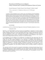
DUCT SYSTEM INSPECTION CHECKLIST
ACCEPTABLE
ý
RIGID DUCTWORK
Pressure Class
Duct Wall
Joints
Seams
Reinforcements
Tie Rods
Crossbreak/Bead
Sealing
Hanger/Support
Insert/Anchors
Duct Liner
Liner Adhesive
Liner Pins
Hangers
Elbows
Turning Vanes
Transitions
Trunk-Branch Fitting
Branch Connection
Extractors
FIRE/SMOKE DAMPERS
Location
Sleeves
Connections
Retaining Angles
Clearances
Control Means
Access
FLEXIBLE DUCT
Duct Grade/Class
Connector Grade
UL/Other Label
Excess Tension
Excess Sag
Supports
Bend Radius
2 in. (51 mm)
Metal Collars
Damage
DEFICIENT
REASON:
Splitters
Volume Dampers
Tap Collars
Terminal Connection
Equipment Connection
Access Doors
Fan Inlet
Fan Outlet
Belt Guards
Vibration Connection
Air Intake
Louvers
Air Exhaust
Curbs
Flashing
Casing
Plenum
In Slab
Underground
Paint/Coatings
Weatherproofing
T
A
I
SP
M
R
=
=
=
=
=
=
Type
Attachment
Incomplete
Spacing
Material
Rating
S
L
C
U
D
=
=
=
=
=
Size
Location
Corrosion
Unclean
Damage
DEFECT LOCATION AND
COMMENT (write in)
MISCELLANEOUS
Grease Duct
Range Hood
Breeching
Furnace Vent
Chimney
Fume Hood
Dishwasher Exhaust Duct
Air Shaft
Through-penetration Firestop
Insulation
Ceiling Plenum Contents
Pressurized Exit
PVC Duct
FRP Duct
Maintenance Access
JOB
CONTRACTOR
INSPECTOR
FOR
HVAC Duct Systems Inspection Guide Second Edition
DATE
2.3
INSPECTION CHECKLIST FOR
FIBROUS GLASS DUCT SYSTEM INSTALLATION
References
SMACNA Standards
North American Installation Manufacturers Association (NAIMA)
Board Manufacturer’s Standards
General
1. Is the duct used within its service limitations?
2. Is system operating within the design limitations for which it was built?
3. Are all sheet metal accessory items galvanized?
4. Is the EI rating printed on the board facing?
5. Is the UL label present on much of the duct surface?
6. Is the system free from visual signs of duct board facing delamination?
Yes
No
Fabrication and Installation
7. Are turning vanes installed in accordance with the Standards? (Pressing your hand into the
cheek of the ell will reveal if specified vanes are being used.)
8. When metal parts are attached, are 21_w in. (63.5 mm) (minimum) square steel washers used
on 16 in. (405 mm) (maximum) centers?
9. When staples can’t be used, are 8 in. (203 mm) cross tabs of approved closure being used in
place of staples? (Tab spacing requirements are 12 in. (305 mm) OC, minimum one per side)
10. Is the system completely free from tears or punctures in the facing?
11. Is the system free from areas where excessive amounts of closure materials, such as
several wraps around a joint, may have been used to conceal potential problem areas?
12. Are all system joints tight, free from bulges, with taped joints showing good workmanship?
13. Are all fittings fabricated in accordance with the Standards and do they demonstrate good
workmanship?
14. Have offsets been installed so duct sections aren’t forced to bend around obstructions?
15. Are all panels in any fitting at least 4 in. (102 mm) long, including male or female joints?
Electric Heaters
16. Is interior sleeve present, properly attached with screws and washers 16 in. (405 mm) on
centers?
17. Is heater separately supported?
18. Are all listed clearances to combustibles and radiation protections in place?
Dampers
19. If a motorized damper operator is being used, is the sheet metal sleeve extended so the
operator is mounted on the same sleeve with the damper?
20. On a manual volume damper, does the quadrant move a full 90 degrees?
Fire Dampers
21. Is sheet metal sleeve present? (Fibrous duct stops at barrier)
22. Is duct properly attached to sleeve with screws and washers 16 in. (405 mm) on centers
and sealed?
Access Doors
23. Is installation in accordance with the Standards?
Grilles, Diffusers, Registers
24. Is the extra weight of the item being separately supported and not dependent on the duct
alone for support?
(EXCEPTION: Registers not greater than 150 in2 (0.097 m2) in area may be attached to the duct with metal
channel without other support.)
2.4
HVAC Duct Systems Inspection Guide Second Edition
Equipment Unit Connection
25. Are sheet metal screws and washers used to secure duct system to flange extensions?
(Mechanical fasteners must be used!)
Yes
No
Closure
26. Are all joints in the system properly sealed?
27. Are closure materials of a listed type as evidenced by presence of UL instruction sheet in
duct board carton? Is tape imprinted?
28. Are there staples or cross tabs, properly spaced, on circumferential joints?
29. Are staples, if used, of the correct type and size, and spaced in proper intervals as
recommended by the duct board manufacturer?
30. Are all pressure-sensitive tape closures rubbed down adequately, with staples or scrim in
facing clearly visible through the tape?
31. If heat-sealable tape closure was used, was it applied correctly, as evidenced by dot color
change?
32. If glass fabric and mastic are used, is the mesh of the glass fabric completely filled with
mastic?
Reinforcement
33. Is reinforcement system of recommended type (formed metal, tie rod, or combination)?
34. Is tie rod wire 12 gage (0.18 mm) or heavier?
35. Is tie rod spacing correct according to duct span, board type, and static pressure?
36. Are tie rod washers 21_w in. (63.5 mm) square and proper gage by type?
37. Do tie rod washers have turned edges facing away from duct board so they won’t cut into it?
38. If tie rods reinforce a butt joint, are rods used on both sides of butt joint?
39. Is wire termination one of those in the Standards?
40. Are anti-sag devices used on ducts 48 in. (1220 mm) span or greater, to support top panel of
ducts?
41. Do tie rods run straight through ducts and not at angles?
42. Are heels of tees, elbows, and end caps reinforced (formed sheet metal channel, tie rod, or
combination)?
43. When formed sheet metal channel reinforcement is used, are sheet metal gages, dimensions,
and spacing correct?
44. On supply ducts, is reinforcing member on the female side of the shiplap?
45. On return ducts, are sheet metal channel reinforcements attached to ducts with screws and
21_w in. (63.5 mm) square washers or 2 × 6 in. (51 × 150 mm) clips?
46. On return ducts, is the reinforcing member attached to the male shiplap side of the joint?
47. For the heels of tees, elbows, end caps, and any other fittings where a panel faces an opening
on the opposite side, is correct reinforcing member (type: sheet metal channel, tie rod, or
combination) applied?
Hangers and Supports
48. Are hangers installed in accordance with the Standards?
49. Are hanger designs in accordance with the Standards?
50. Are accessories that add weight to the duct system separately supported so as not to stress
the system? (consult the standards)
51. Are vertical risers limited to two stories and supported on 12 ft (3650 mm) (maximum)
centers?
52. If formed sheet metal reinforcements are used as hangers, are attachments within 6 in.
(150 mm) of duct sides?
53. Are all fittings supported by hangers in accordance with the standards?
HVAC Duct Systems Inspection Guide Second Edition
2.5
THIS PAGE INTENTIONALLY LEFT BLANK
2.6
HVAC Duct Systems Inspection Guide Second Edition
APPENDIX A
FUNCTIONS OF DUCTED
AIR HANDLING SYSTEMS