Linh kiện q62702 c2383
Bạn đang xem bản rút gọn của tài liệu. Xem và tải ngay bản đầy đủ của tài liệu tại đây (42.46 KB, 5 trang )
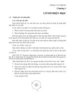
BCR 555
PNP Silicon Digital Transistor
• Switching circuit, inverter, interface circuit,
driver circuit
• Built in resistor (R1 = 2.2kΩ, R2 = 10kΩ)
Type
Marking Ordering Code
Pin Configuration
BCR 555
XDs
1=B
Q62702-C2383
Package
2=E
3=C
SOT-23
Maximum Ratings
Parameter
Symbol
Values
Unit
Collector-emitter voltage
VCEO
50
Collector-base voltage
VCBO
50
Emitter-base voltage
VEBO
5
Input on Voltage
Vi(on)
12
DC collector current
IC
500
mA
Total power dissipation, TS = 79 °C
Ptot
330
mW
Junction temperature
Tj
150
°C
Storage temperature
Tstg
V
- 65 ... + 150
Thermal Resistance
Junction ambient
1)
Junction - soldering point
RthJA
≤ 325
RthJS
≤ 215
K/W
1) Package mounted on pcb 40mm x 40mm x 1.5mm / 6cm2 Cu
Semiconductor Group
1
Nov-27-1996
BCR 555
Electrical Characteristics at TA=25°C, unless otherwise specified
Parameter
Symbol
Values
min.
typ.
Unit
max.
DC Characteristics
Collector-emitter breakdown voltage
V(BR)CEO
IC = 100 µA, IB = 0
Collector-base breakdown voltage
nA
-
100
mA
-
0.65
hFE
70
-
-
VCEsat
V
-
-
0.3
0.4
-
1
0.5
-
1.4
Vi(off)
IC = 100 µA, VCE = 5 V
Input on Voltage
-
-
IC = 50 mA, IB = 2.5 mA
Input off voltage
50
IEBO
IC = 50 mA, VCE = 5 V
Collector-emitter saturation voltage 1)
-
-
VEB = 5 V, IC = 0
DC current gain
-
ICBO
VCB = 40 V, IE = 0
Emitter cutoff current
50
V(BR)CBO
IC = 10 µA, IB = 0
Collector cutoff current
V
Vi(on)
IC = 10 mA, VCE = 0.3 V
Input resistor
R1
1.5
2.2
2.9
kΩ
Resistor ratio
R1/R2
0.19
0.22
0.24
-
AC Characteristics
Transition frequency
fT
IC = 50 mA, VCE = 5 V, f = 100 MHz
MHz
-
150
-
1) Pulse test: t < 300µs; D < 2%
Semiconductor Group
2
Nov-27-1996
BCR 555
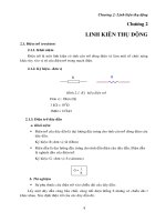
DC Current Gain hFE = f (IC)
VCE = 5V (common emitter configuration)
Collector-Emitter Saturation Voltage
VCEsat = f(IC), hFE = 20
10 3
10 3
mA
hFE
IC
10 2
10 2
10 1
10 1
10 0
10 -1
-1
10
10
0
10
1
10
2
10 0
0.0
mA
0.2
0.4
0.6
V
IC
Input on Voltage Vi(on) = f(IC)
VCE = 0.3V (common emitter configuration)
1.0
V CEsat
Input off voltage Vi(off) = f(IC)
VCE = 5V (common emitter configuration)
10 3
10 1
mA
mA
IC
10 2
IC
10 0
10 1
10 0
10 -1
10 -1
10 -2
-1
10
10
0
10
1
10 -2
0.0
V
V i(on)
Semiconductor Group
0.5
1.0
V
2.0
V i(off)
3
Nov-27-1996
BCR 555
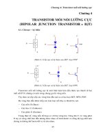
Total power dissipation Ptot = f (TA*;TS)
* Package mounted on epoxy
400
mW
Ptot
TS
300
TA
250
200
150
100
50
0
0
20
40
60
80
100
120 °C 150
TA ,TS
Permissible Pulse Load RthJS = f(tp)
Permissible Pulse Load Ptotmax / PtotDC = f(tp)
10 3
10 4
K/W
RthJS
-
Ptotmax/PtotDC
10 3
10 2
10 1
10 2
0.5
0.2
0.1
0.05
0.02
0.01
0.005
D=0
10 0
10 -1
-6
10
D=0
0.005
0.01
0.02
0.05
0.1
0.2
0.5
10
-5
Semiconductor Group
10
-4
10
-3
10
10 1
-2
-1
10
s 10
tp
0
4
10 0
-6
10
10
-5
10
-4
10
-3
10
-2
-1
10
s 10
tp
0
Nov-27-1996
This datasheet has been download from:
www.datasheetcatalog.com
Datasheets for electronics components.