Ford diesel 2005 6 0l updated coffee table book
Bạn đang xem bản rút gọn của tài liệu. Xem và tải ngay bản đầy đủ của tài liệu tại đây (1.78 MB, 20 trang )
2 0 0 5 6 . 0 L D I T U P D AT E S
2004 Running Changes
• Fuel supply line includes all associated
components.
• During the 2004 MY the rear crankshaft oil
seal was redesigned for improved
performance. This change applies to both
the production seal and the service seal.
2004 Running Changes
• Fuel Supply Line
• VGT Control Valve
• Turbocharger Bearings
• Rear Crankshaft Oil Seal
1
Fuel Supply Line Trap
• A trap was added to the fuel supply line to
prevent fuel from draining out of the
secondary fuel filter housing.
FUEL LINE TRAP
• This new fuel supply line is attached to the
fuel filter housing using a banjo bolt and is
sealed using two copper washers. These
washers must be replaced any time the bolt
is loosened.
• NOTE: This fuel line cannot be retrofitted
to earlier versions of the 6.0L engine.
The fuel filter housing has been modified
to accept the banjo bolt and washers.
COPPER WASHERS
2
VGT Control Valve
• The updated control valve provides faster
response along with improved stability.
• A 200 micron screen has been added to the
oil inlet of the control valve.
• NOTE: The updated VGT control valve
can be used on the 2003 and 2004 MY
turbochargers.
OIL INLET SCREEN
3
1
2 0 0 5 6 . 0 L D I T U P D AT E S
Turbocharger Bearings
FLOATING BEARINGS
• The size of the floating bearings in the
rotating group of the turbocharger has
increased. The two bearings have each
increased in length by 1mm.
• The bearing updates make the rotating
group more robust and reduce shaft motion
effects due to engine vibration inputs.
THRUST BEARING
4
2005 Hardware Changes
2005 Hardware Changes
Component
High-Pressure
Pump
F-Series
E-Series
New V4
New V4
Excursion
Swash Plate
Carryover
Front Cover
Inlet Port
Inlet Port
Carryover
EGR Valve
New Seal New Seal
Carryover
EGR Throttle
Deleted
Deleted
• The Hardware changes for the 2005 MY are
for F-Series and E-Series vehicles only
unless otherwise noted. The serial number
break for Indianapolis built engines is
6344943. Production began June 29, 2004.
• Excursion vehicles carryover the 2004 MY
engine for the first part of the 2005 MY.
• EGR Throttle includes all associated
components.
• High-pressure pump includes all associated
components.
Carryover
5
Horsepower and Torque
Horsepower and Torque
• Torque has been increased to 570 ft. lbs.
• Horsepower remains the same at 325 HP.
• Note: Econoline 6.0L diesel engine
horsepower and torque will remain the
same for 2005 model year (235 HP and
440 ft/lb of torque).
6
2
2 0 0 5 6 . 0 L D I T U P D AT E S
High-Pressure Pump
IPR VALVE
• The high-pressure pump has changed to a
V 4 style piston pump.
• The flow specifications are comparable to
the previous (swash plate style) pump.
• The V 4 pump will provide improved
high-pressure oil system response at low
engine speeds.
HIGH-PRESSURE
PUMP PISTONS
• The long term durability of the high-pressure
pump has been improved due to less wear
area inside of the pump.
CAMSHAFT
High-Pressure Pump Cover
7
Exhaust Up-Pipe Scoop
IPR VALVE
• A redesigned cast aluminum high-pressure
pump cover will be used in 2005 MY due to
the use of a new style high-pressure pump.
• The IPR valve is now mounted in the top of
the high-pressure pump instead of the pump
cover.
• If removal of the pump cover is necessary,
the IPR valve must be removed first.
• NOTE: For the purpose of illustration the
IPR valve heat shield has been removed.
Be sure to reinstall the heat shield after
any service is performed.
HIGH-PRESSURE PUMP
8
High-Pressure Pump Cover Removal
• The high-pressure pump is sealed to the
pump cover with an o-ring around the body
of the pump.
SEALING SURFACE
• The oil drain for the turbocharger remains in
the high-pressure pump cover.
• NOTE: Be sure to cut the silastic T- joint
that seals the high-pressure pump cover,
rear cover, and cylinder block together
prior to removing the high-pressure
pump cover.
PUMP TO COVER O-RING
9
3
2 0 0 5 6 . 0 L D I T U P D AT E S
High-Pressure Pump/Discharge Tube
• The pump is driven by the camshaft gear as
in previous model years.
PUMP MOUNTING BOLTS
• The high-pressure pump discharge tube has
been modified to accommodate the new
high-pressure pump.
DISCHARGE TUBE BOLTS
10
High-Pressure Oil Branch Tube
• The high-pressure pump discharge tube and
branch tube have been redesigned to
incorporate the new style high-pressure
pump.
• The two bolts holding the discharge tube and
the branch tube together are removed when
removing the high-pressure pump. The
discharge tube should be removed with the
high-pressure pump.
DISCHARGE TUBE BOLTS
• NOTE: The 2005 MY high-pressure pump,
pump cover, discharge tube, and branch
tube, are not interchangeable with 2003
and 2004 MY engines. However, the
standpipes did not change.
11
IPR Valve
• The 2005 MY IPR valve uses a 150 micron
perforated plate edge filter. This is an
improvement from the 200 micron filter on
previous models.
• NOTE: For the purpose of illustration the
IPR valve heat shield has been removed.
Be sure to reinstall the heat shield after
any service is performed.
• NOTE: The IPR valve is not
interchangeable with 2003 and 2004 MY
engines.
PERFORATED PLATE EDGE FILTER
12
4
2 0 0 5 6 . 0 L D I T U P D AT E S
High-Pressure Oil Rail Ball Tubes
• The length of the ball tube has been
increased by 2mm to aid in assembly. This
is to reduce the potential risk of damaging
the upper o-ring during the installation of the
high-pressure oil rail.
PART NUMBER
BALL TUBES
• NOTE: The 2005 MY high-pressure oil rail
is not interchangeable with 2004 MY
engines.
• NOTE: The 2004 MY high-pressure oil rail
can be indentified by the C1 suffix of the
International part number. The 2005 MY
high-pressure oil rail can be identified by
the number “5” stamped into one of the
endcaps of the rail.
13
Front Cover
• The coolant inlet ports on the front cover
have been repositioned to accomodate the
new power steering pump design.
COOLANT RETURN FROM HEATER
• NOTE: The 2005 MY front cover is not
interchangeable with 2003 and 2004 MY
engines.
COOLANT RETURN FROM RADIATOR
14
EGR Valve
• The EGR shaft seal has been improved to
reduce exhaust gas leaks past the EGR
valve vent holes.
• The shaft seal improvement requires an
increased return spring tension.
• NOTE: The 2005 MY EGR valve and the
2003/2004 MY EGR valves are not
interchangeable.
• NOTE: The 2005 MY EGR valve can be
identified by the part number 4043H
located on the top of the valve.
SHAFT SEAL
15
5
2 0 0 5 6 . 0 L D I T U P D AT E S
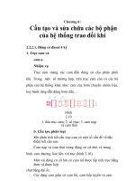
Exhaust Up-Pipe Scoop
EGR FLOW
• An exhaust gas scoop in the exhaust
up-pipe increases exhaust flow to the EGR
cooler.
• This improves the performance of the EGR
valve without the use of the throttle plate.
EXHAUST FLOW
16
Intake Manifold Divider Plates
EGR VALVE
• Two divider plates have been incorporated
into the intake manifold to provide equal
distribution of cooled exhaust gases into
both cylinder heads.
COOLED EXHAUST
DIVIDER PLATES
17
EGR Throttle Plate
2005
2004
• EGR throttle plate (EGRTP) has been
deleted from the air inlet of the intake
manifold for the 2005 MY.
• The 6.0L engine no longer needs the EGR
throttle plate to assist the flow of exhaust
gases through the EGR valve.
EGRTP ACTUATOR AND SENSOR
18
6
DIAGNOSTIC CODES
C - Continuous Operation
O - Self Test - Key On Engine Off (KOEO)
R - Self Test - Key On Engine Running (KOER)
- Added/Changed for 2005 MY
DTC
How Set
Condition Description
P0046 C* O R Turbo/Super Charger Boost Control Solenoid Circuit
Range/Performance
P0069 C*
MAP/BARO Correlation
P0096 C*
Intake Air Temperature Sensor 2 Circuit
Range/Performance
P0097 C* O R Intake Air Temperature Sensor 2 Circuit Low Input
P0098 C* O R Intake Air Temperature Sensor 2 Circuit High Input
P0101 C*
Mass or Volume Air Flow Circuit
Range/Performance
P0102 C*
R Mass or Volume Air Flow Circuit Low Input
P0103 C* O R Mass or Volume Air Flow Circuit High Input
P0107 C* O
Manifold Absolute Pressure/BARO Sensor Low
Input
P0108 C* O
Manifold Absolute Pressure/BARO Sensor High
Input
P0112 C* O R Intake Air Temperature Circuit Low Input
P0113 C* O R Intake Air Temperature Circuit High Input
P0117 C O R Engine Coolant Temperature Circuit Low Input
P0118 C O R Engine Coolant Temperature Circuit High Input
P0148 C
P0196 C*
Fueling Error
R Engine Oil Temperature Sensor Circuit
Range/Performance
P0197 C* O R Engine Oil Temperature Sensor Circuit Low Input
P0198 C* O R Engine Oil Temperature Sensor Circuit High Input
P0219 C
Engine Overspeed Condition
P0230
O
P0231 C* O
Fuel Pump Primary Circuit
Fuel Pump Secondary Circuit Low
P0232
Fuel Pump Secondary Circuit High
O
P0236 C* O
Turbo/Super Charger Boost Sensor A Circuit
Range/Performance
P0237 C* O R Turbo/Super Charger Boost Sensor A Circuit Low
P0238 C* O R Turbo/Super Charger Boost Sensor A Circuit High
P0261 C* O R Cylinder #1 Injector Circuit Low
P0262 C O R Cylinder #1 Injector Circuit High
P0263 C
Cylinder #1 Contribution/Balance
P0264 C* O R Cylinder #2 Injector Circuit Low
P0265 C O R Cylinder #2 Injector Circuit High
P0266 C
Cylinder #2 Contribution/Balance
P0267 C* O R Cylinder #3 Injector Circuit Low
P0268 C O R Cylinder #3 Injector Circuit High
P0269 C
Cylinder #3 Contribution/Balance
P0270 C* O R Cylinder #4 Injector Circuit Low
P0271 C O R Cylinder #4 Injector Circuit High
P0272 C
Cylinder #4 Contribution/Balance
P0273 C* O R Cylinder #5 Injector Circuit Low
P0274 C O R Cylinder #5 Injector Circuit High
P0275 C
Cylinder #5 Contribution/Balance
7
- Not Used on 2005 MY
* - MIL (Malfunction Indicator Light) Illuminates
^ - O/D cancel flashes
[] - Assigned but not used
- Added/Changed for 2004 MY
Fault Trigger/Comments
Internal to PCM. VGT Actuator Circuit check.
30 kPa (4.4 PSI)/Compares BP and MAP at idle.
5 deg.C (41 deg.F)/Checks for minimum change in IAT2
EGR disabled, less than 0.15 volts.
EGR disabled, greater than 4.8 volts.
Indicates a MAF range/performance problem was detected
during normal driving conditions when MAF is enabled. 4.0
volts when RPM is less than 1500, 4.9 volts when RPM is
greater than 1500 RPM.
Indicates MAF sensor circuit low input was detected during
KOEO Self Test or during continuous diagnostic monitoring.
MAF voltage less than 0.35 volts.
Indicates MAF sensor circuit high input detected during
KOEO On-Demand Self Test or during continuous
diagnostic monitoring. MAF voltage is greater than 4.95V.
Checks BP for a signal lower than a specified barometric
pressure expected for normal operations when BP is less
than 0.04 volts. Default 101 kpa (14.6 PSI).
Checks BP for a signal greater than a specified barometric
pressure expected for normal operations when BP is greater
than 4.9 volts. Default 101 kpa (14.6 PSI).
Checks sensor output for a value higher than a maximum
probable temperature when IAT voltage is less than 0.15
volts. Default 77deg.F/25deg. C.
Checks sensor output for a value lower than a minimum
probable temperature when IAT voltage is greater than 4.9
volts. Default 77deg. F/25deg. C.
Checks ECT for a temperature higher than a specified oil
temperature expected for normal operation when ECT
voltage is greater than 0.15 volts. Default 180deg. F/82deg.
C - no fast idle.
Checks ECT for a temperature lower than a specified oil
temperature expected for normal operation when ECT
voltage is greater than 4.78 volts. Default 180deg.
F/82deg.C - no fast idle.
Engine RPM has exceeded requested RPM.
Checks for an EOT temperature signal which is unable to
reach the EOT cold minimum limit whin a specified amount
of time. Function of initial EOT. (in-range fault based off of a
change in EOT and MFDES)
Checks EOT for a temperature higher than a specified oil
temperature expected for normal operations when EOT
voltage is less than 0.15 volts. Default 212deg. F/100deg.C
- no fast idle.
Checks EOT for a temperature lower than a specified oil
temperature expected for normal operations when EOT
voltage is greater than 4.76 volts. Default 212 deg. F/100
deg. C - no fast idle.
PCM recorded excessive engine speed greater than 4300
RPM for more than 5 seconds.
Fuel Pump Relay driver failure.
No voltage present at the Fuel Pump monitor circuit when it
has been commanded “on” for more than 1 second.
Voltage present at the Fuel Pump monitor circuit when it has
NOT been commanded “on” for more than 1 second.
Default inferred MAP - low power, slow acceleration, greater
than 120kpa(2.7PSI) at low idle.
Default inferred MAP - low power, slow acceleration, MAP
voltage is less than 0.039 volts.
Default inferred MAP - low power, slow acceleration, MAP
voltage is greater than 4.91
FICM detected an open the injector circuit.
FICM detected a short in the injector circuit to ground.
When maximum/minimum pulse width adder is exceeded
and cylinder does not converge a fault is set.
FICM detected an open the injector circuit.
FICM detected a short in the injector circuit to ground.
When maximum/minimum pulse width adder is exceeded
and cylinder does not converge a fault is set.
FICM detected an open the injector circuit.
FICM detected a short in the injector circuit to ground.
When maximum/minimum pulse width adder is exceeded
and cylinder does not converge a fault is set.
FICM detected an open the injector circuit.
FICM detected a short in the injector circuit to ground.
When maximum/minimum pulse width adder is exceeded
and cylinder does not converge a fault is set.
FICM detected an open the injector circuit.
FICM detected a short in the injector circuit to ground.
When maximum/minimum pulse width adder is exceeded
and cylinder does not converge a fault is set.
Probable Causes
Diagnostic circuit associated with 1 Amp driver checks for open
circuit, short to ground, and short to power.
VGT, BP, MAP, EGR - System Fault, Biased Sensor, Circuit Integrity.
IAT 2 Biased Sensor, System Fault, PCM.
MAT signal circuit, shorted to ground or defective sensor.
MAT signal circuit, open, short to power or defective sensor.
Damaged MAF sensor-plugged or restricted sensor supply tubeMAF, PCM.
Open MAF sensor circuit-biased sensor, PCM-short to SIGN RTN or
PWR GND on MAF sensor circuit-open in VREF circuit.
Biased sensor, PCM-MAF circuit shorted to VREF.
Circuit is open, shorted to ground.
Circuit is shorted to power
Shorted to ground.
Open in circuit, short to power.
Short to ground on the circuit.
Open in circuit, short to power.
Alternative fuel source, Interference on CKP & CMP, Faulty PCM.
Faulty, Biased sensor, circuit fault, PCM.
Shorted to ground on the circuit.
Open in circuit, short to power.
Improper downshift, Interference on CKP & CMP, Faulty PCM.
Open control circuit, failed fuel pump relay or PCM.
Indicates open, short circuit, relay, inertia switch or fuel pump.
Indicates short to power,sticking relay.
MAP sensor plugged, defective sensor.
MAP circuit short to ground or open, defective sensor.
MAP circuit short to Vref or Vbat, defective sensor.
Injector circuit open or defective coil.
Injector circuit short to ground, defective coil
Injector circuit open or defective coil.
Injector circuit short to ground, defective coil
Injector circuit open or defective coil.
Injector circuit short to ground, defective coil
Injector circuit open or defective coil.
Injector circuit short to ground, defective coil
Injector circuit open or defective coil.
Injector circuit short to ground, defective coil
DIAGNOSTIC CODES
P0276 C* O R Cylinder #6 Injector Circuit Low
P0277 C O R Cylinder #6 Injector Circuit High
P0278 C
Cylinder #6 Contribution/Balance
P0279 C* O R Cylinder #7 Injector Circuit Low
P0280 C O R Cylinder #7 Injector Circuit High
P0281 C
Cylinder #7 Contribution/Balance
P0282 C* O R Cylinder #8 Injector Circuit Low
P0283 C O R Cylinder #8 Injector Circuit High
P0284 C
Cylinder #8 Contribution/Balance
P0297 C
P0298 C*
Vehicle Overspeed Condition
Engine Oil Over Temperature Condition
P0299 C*
Turbo / Super Charger Underboost
P0300 C*
Random Misfire Detected
P0301 C*
Cylinder #1 Misfire Detected
P0302 C*
Cylinder #2 Misfire Detected
P0303 C*
Cylinder #3 Misfire Detected
P0304 C*
Cylinder #4 Misfire Detected
P0305 C*
Cylinder #5 Misfire Detected
P0306 C*
Cylinder #6 Misfire Detected
P0307 C*
Cylinder #7 Misfire Detected
P0308 C*
Cylinder #8 Misfire Detected
P0335 C*
R Crankshaft Position Sensor A Circuit
P0336 C*
R Crankshaft Position Sensor Circuit A
Range/Performance
P0340 C*
R Camshaft Position Sensor A Circuit (Bank 1 or
single sensor)
P0341 C*
R Camshaft Position Sensor A Circuit
Range/Performance (Bank 1 or single sensor)
P0381 C* O
Glow Plug/Heater Indicator Circuit
FICM detected an open the injector circuit.
FICM detected a short in the injector circuit to ground.
When maximum/minimum pulse width adder is exceeded
and cylinder does not converge a fault is set.
FICM detected an open the injector circuit.
FICM detected a short in the injector circuit to ground.
When maximum/minimum pulse width adder is exceeded
and cylinder does not converge a fault is set.
FICM detected an open the injector circuit.
FICM detected a short in the injector circuit to ground.
When maximum/minimum pulse width adder is exceeded
and cylinder does not converge a fault is set.
Vehicle has been driven at speeds above limited speeds
Function of initial EOT
Injector circuit open or defective coil.
Injector circuit short to ground, defective coil
Fault sets when the difference between EP and
commanded EP exceeds the limit for > 30 seconds.
Unknown or random misfire when calculated instantaneous
crankshaft acceleration exceeds a specified value a misfire
event is detected.
Faulty EP sensor, VGT control valve slow to respond, Stuck VGT
valve, faulty PCM.
Injector circuit open or defective coil.
Injector circuit short to ground, defective coil
Injector circuit open or defective coil.
Injector circuit short to ground, defective coil
Faulty PCM, Interference on VSS.
Checks for an EOT temperature signal which is unable to reach the
EOT hot minimum limit (EOT_HOT_LMN) within a specified amount
of time.
Indicates when cylinder 1 is misfiring due to a loss of
compression.
Indicates when cylinder 2 is misfiring due to a loss of
compression.
Indicates when cylinder 3 is misfiring due to a loss of
compression.
Indicates when cylinder 4 is misfiring due to a loss of
compression.
Indicates when cylinder 5 is misfiring due to a loss of
compression.
Indicates when cylinder 6 is misfiring due to a loss of
compression.
Indicates when cylinder 7 is misfiring due to a loss of
compression.
Indicates when cylinder 8 is misfiring due to a loss of
compression.
PCM monitors CKP signal for a unique pattern to indicate
Poor connection, defective sensor, electrical noise.
piston position. Checks for total absence of the CKP signal.
CKP signal intermittent.
Poor connection, defective sensor, electrical noise.
PCM monitors CMP signal for a unique pattern to indicate
Poor connection, defective sensor, electrical noise.
piston position. Checks for total absence of the CMP signal.
CMP signal intermittent.
Poor connection, defective sensor, electrical noise.
Indicator Circuit Check - Instrument cluster driver checks for
open circuit, or short circuit when lamp turns on and off.
EGR Valve Position does not match desired, limits based on
engine speed / load.
EGR Valve Position does not match desired, limits based on
engine speed / load.
EGR actuator circuit check. Diagnostic circuit associated
with 1 Amp driver Internal to PCM.
+/- 0.10 EGRP error from commanded to actual EGRP during normal driving conditions.
EGR is disabled when EGR voltage is less than 0.30 volts.
EGR is disabled when EGR voltage is greater than 4.9 volts.
Checks EGRP for a lower than a specified position for
normal operation.
Checks EGRP for a higher than a specified position for
normal operation.
Fuel Level Indicator (FLI) Circuit Check - Instrument cluster
driver checks for open circuit, or short circuit.
Open/Short circuit, lamp, fuse, PCM.
Maximum EP when the engine is not running 150 kpa (21.8
PSI) absolute.
Minimum EP when the engine is running, Pressure difference of +/-10 kPa (1.5 PSI) from desired.
EGR disabled, default inferred for VGT operation when EGR
voltage is less than 0.03 volts.
EGR disabled, default inferred for VGT operation when EGR
voltage is greater than 4.8 volts.
EP is higher than EP desired by 260 kpa (37.7 PSI) for
greater than 30 seconds.
Faulty EP Sensor, PCM.
P0480 C
R Fan 1 Control Circuit
P0487 C* O R EGR Throttle Position Control Circuit
EGR actuator circuit check.
open circuit, short to ground, and short to power.
P0488 C*
Checks for a difference in commanded and actual EGRTP
Fault sets when the difference between EGRTP and commanded
EGRTP exceeds the limit for a specified time.
Sensor, circuit, PSM, PSOM, low transmission fluid.
P0401 C*
Exhaust Gas Recirculation Flow Insufficient
Detected
P0402 C*
Exhaust Gas Recirculation Flow Excessive
Detected
P0403 C* O R Exhaust Gas Recirculation Control Circuit
P0404 C*
Exhaust Gas Recirculation
Range/Performance
P0405 C* O R Exhaust Gas Recirculation
P0406 C* O R Exhaust Gas Recirculation
P0407 C* O R Exhaust Gas Recirculation
Control Circuit
Sensor A Circuit Low
Sensor A Circuit High
Sensor B Circuit Low
P0408 C* O R Exhaust Gas Recirculation Sensor B Circuit High
P0460 C O R Fuel Level Sensor A Circuit
P0462 C O R Fuel Level Sensor A Circuit Low Input
P0463 C O R Fuel Level Sensor A Circuit High Input
P0470 C* O
Exhaust Pressure Sensor
P0471 C*
Exhaust Pressure Sensor Range/Performance
P0472 C* O R Exhaust Pressure Sensor Low Input
P0473 C* O R Exhaust Pressure Sensor High Input
P0478 C*
Exhaust Pressure Control Valve High Input
EGR Throttle Position Control Range/Performance
P0500 C
P0528 C
P0562 C*
Vehicle Speed Sensor A
R Fan Speed Sensor Circuit No Signal
R System Voltage Low
Vehicle speed sensor malfunction.
P0563
P0565
P0566
P0567
R
R
R
R
PCM voltage continuously more than 23.3v.
KOER switch test(code set if cruise not present).
KOER switch test(code set if cruise not present).
KOER switch test(code set if cruise not present).
System Voltage High
Cruise Control ON Signal
Cruise Control OFF Signal
Cruise Control RESUME Signal
PCM voltage less than 7v - cause of no start/misfire.
EGR Valve stuck or sticking - EGR Valve Position Sensor Bias EP Sensor bias.
EGR Valve stuck or sticking - EGR Valve Position Sensor Bias EP Sensor bias.
Open circuit, short to ground, and short to power.
Faulty EGR sensor, valve or PCM integrity of EGR position circuit.
EGRP circuit short to ground or open, defective sensor.
EGRP circuit short to Vref or Vbat, defective sensor.
Circuit is shorted to ground.
Circuit is shorted to 5V.
Faulty EP Sensor, PCM or VGT.
EP circuit is short to ground or open, defective sensor.
EP circuit is short to Vref or Vbat, defective sensor.
Faulty EP sensor, VGT control valve slow to respond, Stuck VGT
valve, faulty PCM.
Low VBAT, loose connections/resistance in circuit, Vref engine
concerns.
Charging system fault.
Open/short circuit, switch failure, PCM failure.
Open/short circuit, switch failure, PCM failure.
Open/short circuit, switch failure, PCM failure.
8
DIAGNOSTIC CODES
P0568
P0569
P0571
O
R Cruise Control SET Signal
R Cruise Control COAST Signal
Brake Switch A Circuit
P0603 C
P0605
P0606
P0611
P0620
P0623
P0645
P0649
P0670
P0671
P0672
P0673
P0674
P0675
P0676
P0677
P0678
P0683
O
C*
C*
C
C
C
C
C*
C*
C*
C*
C*
C*
C*
C*
C*
C*
O
O
O
O
O
O
O
O
O
O
O
O
O
O
O
R
R
R
R
R
R
R
R
R
R
R
R
R
R
R
R
P0700 C O R
P0703
R
P0704 C
Powertrain Control Module Keep Alive Memory
(KAM) Error
No historical faults output during self test.
Open/short circuit, switch failure, PCM failure.
Open/short circuit, switch failure, PCM failure.
Cruise control code will be set on every switch test on vehicles not
equipped with cruise control.
Disconnected/Discharged Battery, Open PCM pin, faulty PCM.
Powertrain Control Module Read Only Memory
(ROM) Error
ECM / PCM Processor
Fuel Injector Control Module Performance
Generator 1 Control Circuit
Generator Lamp Control Circuit
A/C Clutch Relay Control Circuit
Cruise Control Lamp Control Circuit
Glow Plug Module Control Circuit
Cylinder 1 Glow Plug Circuit
Cylinder 2 Glow Plug Circuit
Cylinder 3 Glow Plug Circuit
Cylinder 4 Glow Plug Circuit
Cylinder 5 Glow Plug Circuit
Cylinder 6 Glow Plug Circuit
Cylinder 7 Glow Plug Circuit
Cylinder 8 Glow Plug Circuit
Glow Plug Control Module to PCM Communication
Circuit
Transmission Control System (MIL Request)
Brake Switch B Input Circuit
PCM failure
Defective PCM.
FICM memory fault will set if a RAM or ROM fault exists.
Loss of FICM power or other internal FICM failure.
Glow plug control module control line failure
Glow plug #1 failure
Glow plug #2 failure
Glow plug #3 failure
Glow plug #4 failure
Glow plug #5 failure
Glow plug #6 failure
Glow plug #7 failure
Glow plug #8 failure
GPCM glow plug control module communication line failure
Open/grounded circuit, open/shorted GPCM, failed PCM
Open/shorted circuit, faulty glow plug, failed GPCM
Open/shorted circuit, faulty glow plug, failed GPCM
Open/shorted circuit, faulty glow plug, failed GPCM
Open/shorted circuit, faulty glow plug, failed GPCM
Open/shorted circuit, faulty glow plug, failed GPCM
Open/shorted circuit, faulty glow plug, failed GPCM
Open/shorted circuit, faulty glow plug, failed GPCM
Open/shorted circuit, faulty glow plug, failed GPCM
Open/shorted circuit, failed GPCM, failed PCM
KOER switch test.
Open/short circuit, switch, PCM, failed to activate during KOER
switch test.
Open/short circuit, switch, PCM, failed to activate during KOER
switch test.
R Clutch Switch Input Circuit
P0830
R Clutch Pedal Switch A Circuit
P0833
R Clutch Pedal Switch B Circuit
P1000 C O R OBD Systems Readiness Test Not Complete
P1001
R KOER not able to complete, KOER aborted
P1102 C*
Mass Air Flow Sensor In Range But Lower Than
Expected
P1139 C O R Water in Fuel Indicator Circuit
P1148 C O R Generator 2 Control Circuit
P1149 C* O R Generator 2 Control Circuit High
P1184
R Engine Oil Temperature Sensor Out Of Self Test
Range
P1260 C
Theft Detected, Vehicle Immobilized
P1284
R Aborted KOER - Injector Control Pressure Regulator
P1334 C
R EGR Throttle Position Sensor Minimum Stop
Performance
P1335 C
R EGR Position Sensor Minimum Stop Performance
P1378 C O R FICM Supply Voltage Circuit Low
P1379 C O R FICM Supply Voltage Circuit High
P1397
R System Voltage Out Of Self Test Range
P1408
R EGR Flow Out Of Self Test Range
P1464
O R A/C Demand Out Of Self Test Range
P1501
O R Vehicle Speed Sensor Out Of Self Test Range
P1502
O R Invalid Test - Auxiliary Power Control Module
Functioning
P1531
R Invalid Test - Accelerator Pedal Movement
P1536
R Parking Brake Switch Circuit
P1633 C* O R Keep Alive Power Voltage Too Low
P1635 C* O R Tire/Axle Out of Acceptable Range
P1639 C* O R Vehicle ID Block Corrupted, Not Programmed
P1703
O R Brake Switch Out Of Self Test Range
P1705
O R Transmission Range Circuit Not Indicating
Park/Neutral During Self Test
P1725
R Insufficient Engine Speed Increase During Self Test
P1726
R Insufficient Engine Speed Decrease During Self Test
P2067 C O R Fuel Level Sensor B Circuit Low Input
P2068 C O R Fuel Level Sensor B Circuit High Input
P2104 C
Throttle Actuator Control System - Forced Idle
P2122 C O R Throttle/Pedal Position Sensor/Switch D Circuit Low
Input
P2123 C O R Throttle/Pedal Position Sensor/Switch D Circuit High
Input
P2127 C O R Throttle/Pedal Position Sensor/Switch E Circuit Low
Input
P2128 C O R Throttle/Pedal Position Sensor/Switch E Circuit High
Input
P2132 C O R Throttle/Pedal Position Sensor/Switch F Circuit Low
Input
P2133 C O R Throttle/Pedal Position Sensor/Switch F Circuit High
Input
P2138 C O R Throttle/Pedal Position Sensor/Switch D / E Voltage
Correlation
P2139 C O R Throttle/Pedal Position Sensor/Switch D / F Voltage
Correlation
P2140 C O R Throttle/Pedal Position Sensor/Switch E / F Voltage
Correlation
9
KOER switch test(code set if cruise not present).
KOER switch test(code set if cruise not present).
Brake switch A circuit malfunction
KOER switch test.
Drive cycle is not complete.
Conditions not met.
A/C, Parking Brake, Clutch, PRNDL, (EOT, ETC.)
Indicates fault in circuit.
Faulty sensor, Open or Short in circuit.
Engine not warm enough to run KOEO CCT - aborts test.
Engine not warm enough, leaking thermostat, circuit failure.
ICP failure--Aborts KOER CCT test
Checks for a maximum closed and a minimum open
position voltage.
Fault sets when the EGRP closed position exceeds the
maximum limit at initial key on.
FICM detects logic power low, less than 7 volts.
FICM detects excessive voltage, greater than 16 volts.
See codes P2284, P2285, P2286, P2288, P2623
EGRC output circuit check - engine off test only
Aborts KOER Test.
Aborts test - KOER on demand, CCT, or switch test.
Aborts test - KOER on demand, CCT, or switch test.
Low batteries, loose connections/resistance in circuit, defective relay.
Charging system fault.
Voltage too high or low for glow plug monitor test.
EGR Control circuit open, short to Vref, Vbat, ground, defective coil.
A/C switch not in "off" position, A/C circuit short to power.
Vehicle speed detected during test, faulty VSS, PCM.
APCM active while KOER test is running.
Aborts test - KOER on demand, CCT test.
KOER switch test.
Accelerator pedal incorrect position during test, faulty AP, PCM.
Failed to activate switch during test, circuit, switch, PCM.
Not in park during KOEO or KOER.
Operator error, circuit failure, faulty sensor, PCM.
Pedal Sensors will use SAE D,E,F codes
Pedal Sensors will use SAE D,E,F codes
Pedal Sensors will use SAE D,E,F codes
DIAGNOSTIC CODES
P2199 C*
P2262 C*
P2263 C*
Intake Air Temperature 1/2 Correlation
Correlation between IAT1 and IAT2 are not at expected
values.
Turbo/Super Charger Boost Pressure not Detected No boost pressure increase was detected.
- Mechanical
Turbo/Super Charger System Performance
Open/shorted circuit, bias sensor, PCM
MAP hose, MAP sensor, CAC system leaks, Intake leaks, EP
sensor, exhaust restriction.
MAP hose, MAP sensor, CAC system leaks, Intake leaks, EP
sensor, exhaust restriction, exhaust leaks.
Drain water in fuel separator, defective WIF sensor, circuit integrity.
P2269 C O R Water in Fuel Condition
Indicates water in fuel.
P2284 C
Default inferred ICP, ICP desired does not equal ICP
signal, difference of 362psi/2.5mpa.
Default open loop control - underrun at idle, ICP is less than
0.04 volts.
Default open loop control - underrun at idle, ICP is greater
than 4.91 volts.
Default inferred ICP is used, ICP is greater than
3675psi/25mpa.
Default inferred ICP, KOEO ICP is greater than
1161psi/8mpa.
Default inferred ICP is used, ICP is below desired pressure
See diagnostic manual - ICP system.
No start ICP is less than 725psi/5mpa.
See diagnostic manual - ICP system
P2552 C O R FICMM Circuit - Throttle/Fuel Inhibit Circuit
No signal from the FICM Monitor circuit
Circuit open/short, FICM, PCM
P2614 C O R Camshaft Position Output Circuit / Open
CMPO signal intermittent
Poor connection, electrical noise. In CMPO from PCM
P2617 C O R Crankshaft Position Output Circuit / Open
CKPO signal intermittent
Poor connection, electrical noise. In CKPO from PCM
P2623 C* O R Injector Control Pressure Regulator Circuit
IPR circuit failure
Open/grounded circuit, stuck IPR, loose connection
R Injector Control Pressure Sensor Circuit
Range/Performance
P2285 C O R Injector Control Pressure Sensor Circuit Low
P2286 C O R Injector Control Pressure Sensor Circuit High
P2288 C
R Injector Control Pressure Too High
P2289 C O
Injector Control Pressure Too High - Engine Off
P2290 C O
Injector Control Pressure Too Low
P2291 C
Injector Control Pressure Too Low - Engine
Cranking
Exhaust Gas Recirculation Cooler System
Performance
P2457 C*
ICP circuit short to ground or open, defective sensor.
ICP circuit short, Vref or Vbat, defective sensor.
See diagnostic manual - ICP system.
ICP signal ground, circuit open, defective sensor.
See diagnostic manual - ICP system.
U0101 C O R Lost Communication with TCM
U0105 C O R Lost Communication with FICM
Check CAN2H/CAN2L circuits, PCM, or FICM issue.
U0155 C O R Lost Communication with Instrument Cluster
U0306 C O R Software Incompatibility with FICM
10
F - S E R I E S ( S I N G L E A LT. )
Engine Mounted Components
SENSORS
Regulator
Sense
**
**
CAM
POSITION
CRANK
POSITION
ICP
EOT
ECT
**
B+
**
IAT2
EFC Module
EP
EOP
Switch
VPWR
VBPWR
Speed
Sensor
I-Sense
I
F
RCS - NC
Fan
Clutch
A
C
FSS
D
FC-V
TPWRGND
A/C Clutch
2 1
2 1
B
C
2 1
A
2 1
2 1
B
C
Alternator
To Battery
A
RCS - NO
B
A
Alternator
Power
4
3
2
1
8
7
6
5
Elec Fan
Ctrl
TPWRGND
FSS
VBPWR
FC-V
VGTCH
EP
VREF
SIGRTN
IAT2
ECT
EOT
ICP
CMP+
CMP CMP/CKP Sh.- PWRGND
CKP +
CKP IPR
VGTC
EGRVC
EGRVP
ACTUATORS
1 2
1 2
A
B
C
D
GPE
GPD
E
KEYPWR
MPR
D
C
B
A
FICM Logic Pwr
FICM Main Pwr
FICM Main Pwr
FICM Pwr Gnd
FICM Pwr Gnd
Cylinder #4
Cylinder #2
IPR
Actuator
VGT
Actuator
Cylinder #8
Cylinder #6
EGR
Actuator/
EGRVP
N/C
3
4
1
2
3
4
1
2
3
4
1
2
3
4
1
N/C
2
X3 - Pin 7
X3 - Pin 27
X3 - Pin 8
X3 - Pins 4, 23
X3 - Pins 24, 25
X3 - Pins 1, 2, 3
X3 - Pins 22, 26
CKPO
X3 - Pin 9
CMPO
X3 - Pin 30
IDMCANH
X3 - Pin 31
IDMCANL
X3 - Pin 32
IDMCANS
X3 - Pin 29
X3 - Pin 28
X2 - Pin 3
(Orientation = Looking into
terminals on connector)
PURPLE = V inj (48 VOLTS)
X2 - Pin 23
X2 - Pin 7
X2 - Pin 24
X1 - Pin 4
Lt. BLUE = V ref (5 VOLTS)
X1 - Pin 21
X1 - Pin 7
GREEN = SIGNAL CIRCUIT
Dk Blue = Data Communication Link
BLACK = GROUND CIRCUIT
RED = 12 VOLTS (V Batt)
**
X1 - Pin 22
X1 - Pin 1
X1 - Pin 23
X1 - Pin 6
X1 - Pin 24
X2 - Pin 2
Gold Plated Pins
X2 - Pin 17
X2 - Pin 6
The following pins in the PCM are tin plated:
J1-C1: 01,11,12,23,24,34,35,46
J1-C2: 01,11,12,23,24,34,35,46
J1-C3: 01,07,08,15,16,22,23,30
All of the other pins are gold plated
X2 - Pin 18
FUEL INJECTORS
X1 - Pin 2
X1 - Pin 19
X1 - Pin 5
X1 - Pin 20
X2 - Pin 4
X2 - Pin 19
8 2 7
9 1 6
X2 - Pin 1
X2 - Pin 21
X2 - Pin 5
X2 - Pin 22
X1 - Pin 3
2
1
4
3
2
1
4
3
2
1
4
3
2
1
X1 - Pin 17
4
X1 - Pin 8
3
X1 - Pin 18
3
Glow Plug
ControlModule
3
X2 - Pin 8
X2 - Pin 20
9 1 6
8 2 7
X3 - Pin 5
X3 - Pin 10
Cylinder #1
D
C
B
A
11
Cylinder #3
Cylinder #5
Cylinder #7
Injector Pinout
1 - Open Coil Power
2 - Open Coil Ground
3 - Close Coil Power
4 - Close Coil Ground
Siemens
FICM
Module
NOTE: For clarity of the print all three FICM
connectors are shown together as one.
The pin numbers are color coded, blue
for X1, red for X2, and black for X3
FICMM
CAN2H
CAN2L
CKPO
CMPO
F - S E R I E S ( S I N G L E A LT. )
12 Way On/Off Engine Connector
BCPIL
PTOC
A/C Clutch (-)
5
Blunt Cut
4
7
A/C Clutch (+)
Type 4
Ground
2
FICM Power
Relay
3
V Power
10
FICM Ground
FICM Main Pwr
12
FICMLogic Pwr
MPR
8
KEYPWR
M
Inertia
Switch
Type 4
Ground
11
Fuel Pump
B+
B+
KEYPWR
9
I-Sense
FP Relay
KEYPWR
B+
50 Amp
6
Key Power
EOP Switch
VPWR
B+
10 Amp
PCM Power
Relay
A/C Relay
B+
Type 4
Ground
1
HFCM Mod
8 Way On/Off
Engine Connector
6
7
8
3
Vehicle Mounted Components
Type 2
Ground
2
GEN2C
BAP
5
GEN1C
4
N/C
1
N/C
AHC
GEN1C
GEN2C
TPWRGND
FSS
VBPWR
FC-V
VGTCH
EP
VREF
N/C
N/C
**
6
34, 46
46
40
14
11, 23
11
19
27
2
5
25
32
45
44
32
9
EOT
ICP
44
39
29
16
CMP+
31
33
CMP -
43
45
42
42
30
21
CKP IPR
VGTC
41
43
2
38
10
41
EGRVC
EGRVP
EGRTP
23
17
33
30
38
26
GPE
GPD
N/C
4
22
36
BCPIL
N/C
1
DPCAT
12
20
24
25
15
29
16
3
37
17
36
7
36
8
28
9
18
8
EGRT2
EGRT1
ITAC
FICMM
CAN2H
CAN2L
CKPO
CMPO
4
34
15
28
3
37
22
26
1
19
7
20
12
35
J1- C2 Pocket
PCM122 Engine
Connector (46
Way)
**
Visteon
PCM122
13
14
27
31
24
10
6
1
8
9
VPWR
RPM
MPH
16
CAN1L
KAPWR B+
B+
A
B
C
D
E
F
CAN1H
PWRGND
**
2
FPM
ACCR
FPC
PTOGND
PTOVREF
Blunt Cut
BCPSW
FEPS
A
ACPSW
SIGRTN
VREF
MAF
MAFRTN
IAT1
BARO
MAP
PBPP
GENIL
Type 2
Ground
N/C
APP1
SIGRTN2
VREF2
9
12
13
14
2
17
18
19
20
21
26
30
1
25
22
29
27
28
3
C
ACCS
TOWS(Auto)
KEYPWR
KEYPWR
KEYPWR
CPP(Man)
BPS
BPP
D
To AC System
B+
B+
Type 2
Ground
VSO
After Market
Circuits
Blunt Cut
M
ABS Module
P131
Starter Motor
Public CAN
Data Bus
CAN1H
CAN1L
CPPL
NO
SCCS
SCCSRTN
CSEGND
PTORPM
THREE
TRACK
PEDAL
HFCM
Water In Fuel Probe
GEM 4X4 Module
PTO
VSS
Ignition Switch
START
NO
CTO
TRO_P
Pressure Ctrl
Solenoid #1
Type 2
Ground
CRUISE CONTROL
Type 6
Ground
120 Ohms
180 Ohms
300 Ohms
510 Ohms
1000 Ohms
Pressure Ctrl
Solenoid #2
2200 Ohms
Blunt Cut
TSPC
RESUME
SET -
SET+
RESUME
Pressure Ctrl
Solenoid #3
ON
7
6
24 Way
Transmission
Connector
Pressure Ctrl
Solenoid #4
5R110 Transmission Wiring Assembly
24
PCA
Pressure Ctrl
Solenoid #5
12
PCB
PCC
3
5
PCD
Converter
Clutch Ctrl
Solenoid
4
PCE
1
PCF
8
PCG
Line Pressure
Solenoid
10
PSA
14
N/C
N/C
PSB
PSC
16
N/C
9
N/C
11
N/C
TFT
TSIGRTN
13
PSD
PSE
TRS
**
TSS/ISS
**
Back UP Lamp
Relay Control
OSS
VPWR
B+
18
22
VBPWR
21
TR-P
LH BKP
Lamp
RH BKP
Lamp
15
TPWRGND
17
TSS
ISS
Type 4
Ground
OSS
RLC
TRO_N1
TRO_PN
24
5
8
Starter Relay
CTRL
CPSW - NC
NC
SMC
WFS
TRO_N2
N/C
4
5
**
APP2
20
11
1
4
APP3
12A650-???
Module
10
1
3
OFF
7
**
PWRGND
VPWR
N/C
J1- C1 Pocket
PCM122 Chassis
Connector (46
Way)
IAT2
ECT
EGRTPC1
EGRTPC2
PTOC
MAP
MAF/IAT1
Diagnostics Connector
5
SIGRTN
CMP/CKP Sh.- PWRGND
CKP +
N/C
N/C
INSTRUMENT CLUSTER
TCS
TCIL
Blunt Cut
N/C
N/C
J1- C3 Pocket
PCM122 Trans
Connector (30 Way)
**
12
F - S E R I E S ( D U A L A LT. )
Engine Mounted Components
SENSORS
Regulator
Sense
**
**
CAM
POSITION
CRANK
POSITION
ICP
EOT
ECT
**
B+
**
IAT2
EFC Module
EP
EOP
Switch
VPWR
VBPWR
Speed
Sensor
I-Sense
I
F
RCS - NC
Fan
Clutch
A
C
FSS
D
FC-V
TPWRGND
A/C Clutch
2 1
2 1
B
C
2 1
A
2 1
2 1
B
C
To Battery
A
RCS - NO
B
A
Alternator
Alternator
Power
4
3
2
1
8
7
6
5
Elec Fan
Ctrl
TPWRGND
FSS
VBPWR
FC-V
VGTCH
EP
VREF
SIGRTN
IAT2
ECT
EOT
ICP
CMP+
CMP CMP/CKP Sh.- PWRGND
CKP +
CKP IPR
VGTC
EGRVC
EGRVP
ACTUATORS
1 2
1 2
A
B
C
D
GPE
GPD
E
KEYPWR
MPR
D
C
B
A
FICM Logic Pwr
FICM Main Pwr
FICM Main Pwr
FICM Pwr Gnd
FICM Pwr Gnd
Cylinder #4
Cylinder #2
IPR
Actuator
VGT
Actuator
Cylinder #8
Cylinder #6
EGR
Actuator/
EGRVP
N/C
3
4
1
2
3
4
1
2
3
4
1
2
3
4
1
N/C
2
X3 - Pin 7
X3 - Pin 27
X3 - Pin 8
X3 - Pins 4, 23
X3 - Pins 24, 25
X3 - Pins 1, 2, 3
X3 - Pins 22, 26
CKPO
X3 - Pin 9
CMPO
X3 - Pin 30
IDMCANH
X3 - Pin 31
IDMCANL
CKPO
X3 - Pin 28
CMPO
X2 - Pin 23
X2 - Pin 7
X2 - Pin 24
X1 - Pin 4
Lt. BLUE = V ref (5 VOLTS)
X1 - Pin 21
X1 - Pin 7
GREEN = SIGNAL CIRCUIT
Dk Blue = Data Communication Link
BLACK = GROUND CIRCUIT
RED = 12 VOLTS (V Batt)
**
X1 - Pin 22
X1 - Pin 1
X1 - Pin 23
X1 - Pin 6
X1 - Pin 24
X2 - Pin 2
Gold Plated Pins
X2 - Pin 17
X2 - Pin 6
The following pins in the PCM are tin plated:
J1-C1: 01,11,12,23,24,34,35,46
J1-C2: 01,11,12,23,24,34,35,46
J1-C3: 01,07,08,15,16,22,23,30
All of the other pins are gold plated
X2 - Pin 18
FUEL INJECTORS
X1 - Pin 2
X1 - Pin 19
X1 - Pin 5
X1 - Pin 20
X2 - Pin 4
X2 - Pin 19
8 2 7
9 1 6
X2 - Pin 1
X2 - Pin 21
X2 - Pin 5
X2 - Pin 22
X1 - Pin 3
1
4
3
2
1
4
3
2
1
4
3
2
1
X1 - Pin 17
4
X1 - Pin 8
3
X1 - Pin 18
3
Glow Plug
ControlModule
3
X2 - Pin 8
X2 - Pin 20
2
9 1 6
8 2 7
X3 - Pin 5
X3 - Pin 10
Cylinder #1
D
C
B
A
13
Cylinder #3
Cylinder #5
Cylinder #7
Injector Pinout
1 - Open Coil Power
2 - Open Coil Ground
3 - Close Coil Power
4 - Close Coil Ground
CAN2H
CAN2L
X3 - Pin 32
IDMCANS
X3 - Pin 29
X2 - Pin 3
(Orientation = Looking into
terminals on connector)
PURPLE = V inj (48 VOLTS)
FICMM
Siemens
FICM
Module
NOTE: For clarity of the print all three FICM
connectors are shown together as one.
The pin numbers are color coded, blue
for X1, red for X2, and black for X3
F - S E R I E S ( D U A L A LT. )
12 Way On/Off Engine Connector
BCPIL
PTOC
A/C Clutch (-)
5
Blunt Cut
4
7
A/C Clutch (+)
Type 4
Ground
2
FICM Power
Relay
3
V Power
10
FICM Ground
FICM Main Pwr
12
FICMLogic Pwr
MPR
8
Key Power
KEYPWR
Fuel Pump
B+
B+
M
KEYPWR
9
Inertia
Switch
Type 4
Ground
11
I-Sense
FP Relay
KEYPWR
B+
50 Amp
6
EOP Switch
VPWR
B+
10 Amp
PCM Power
Relay
A/C Relay
B+
Type 4
Ground
1
HFCM Mod
8 Way On/Off
Engine Connector
6
7
8
3
Vehicle Mounted Components
Type 2
Ground
2
GEN2C
BAP
5
GEN1C
4
N/C
1
N/C
AHC
GEN1C
GEN2C
TPWRGND
FSS
VBPWR
FC-V
VGTCH
EP
VREF
N/C
N/C
**
6
34, 46
46
40
14
11, 23
11
19
27
2
5
25
32
IAT2
ECT
45
44
32
9
EOT
ICP
44
39
29
16
CMP+
31
33
CMP -
43
45
42
42
30
21
CKP IPR
VGTC
41
43
2
38
10
41
EGRVC
EGRVP
EGRTP
23
17
EGRTPC1
EGRTPC2
PTOC
GPE
GPD
N/C
4
22
36
BCPIL
N/C
1
DPCAT
33
30
38
26
12
20
24
25
15
29
16
3
37
17
36
7
36
8
28
9
18
8
EGRT2
EGRT1
ITAC
FICMM
CAN2H
CAN2L
CKPO
CMPO
4
34
15
28
37
3
22
26
1
19
7
20
12
35
J1- C2 Pocket
PCM122 Engine
Connector (46
Way)
**
Visteon
PCM122
13
14
27
31
24
10
6
MAP
1
8
9
VPWR
RPM
MPH
I-Sense
16
CAN1L
KAPWR B+
B+
A
B
C
D
E
F
CAN1H
PWRGND
**
2
3
Alternator
FPC
PTOGND
PTOVREF
Blunt Cut
BCPSW
FEPS
A
ACPSW
SIGRTN
VREF
MAF
MAFRTN
IAT1
BARO
MAP
PBPP
Type 2
Ground
GENIL
APP1
SIGRTN2
VREF2
9
12
13
14
2
17
18
19
20
21
26
30
1
25
22
29
27
28
3
C
ACCS
TOWS(Auto)
KEYPWR
KEYPWR
KEYPWR
CPP(Man)
BPS
BPP
D
To AC System
B+
B+
Type 2
Ground
VSO
After Market
Circuits
Blunt Cut
M
ABS Module
P131
Starter Motor
Public CAN
Data Bus
CAN1H
CAN1L
CPPL
NO
SCCS
SCCSRTN
THREE
TRACK
PEDAL
HFCM
Water In Fuel Probe
GEM 4X4 Module
PTO
VSS
Ignition Switch
START
NO
CTO
TRO_P
Pressure Ctrl
Solenoid #1
Type 2
Ground
CRUISE CONTROL
CSEGND
PTORPM
Type 6
Ground
120 Ohms
180 Ohms
300 Ohms
510 Ohms
1000 Ohms
Pressure Ctrl
Solenoid #2
2200 Ohms
Blunt Cut
TSPC
7
6
24 Way
Transmission
Connector
RESUME
SET -
SET+
RESUME
Pressure Ctrl
Solenoid #3
ON
Pressure Ctrl
Solenoid #4
5R110 Transmission Wiring Assembly
24
PCA
Pressure Ctrl
Solenoid #5
12
PCB
PCC
3
5
PCD
Converter
Clutch Ctrl
Solenoid
4
PCE
1
PCF
8
PCG
Line Pressure
Solenoid
10
PSA
14
N/C
N/C
PSB
PSC
PSD
PSE
16
N/C
9
N/C
11
N/C
13
TFT
TSIGRTN
TRS
**
TSS/ISS
**
Back UP Lamp
Relay Control
OSS
VPWR
B+
18
22
VBPWR
21
TR-P
LH BKP
Lamp
RH BKP
Lamp
15
TPWRGND
17
TSS
ISS
Type 4
Ground
OSS
RLC
TRO_N1
TRO_PN
24
5
8
Starter Relay
CTRL
CPSW - NC
NC
SMC
WFS
TRO_N2
N/C
4
5
**
APP2
20
11
1
4
APP3
OFF
10
1
A F I
FPM
ACCR
12A650-???
Module
7
**
B+
PWRGND
VPWR
N/C
J1- C1 Pocket
PCM122 Chassis
Connector (46
Way)
MAF/IAT1
Regulator
Sense
Diagnostics Connector
5
SIGRTN
CMP/CKP Sh.- PWRGND
CKP +
N/C
N/C
INSTRUMENT CLUSTER
TCS
TCIL
Blunt Cut
N/C
N/C
J1- C3 Pocket
PCM122 Trans
Connector (30 Way)
**
14
®
E C O N O L I N E ( S I N G L E A LT. )
Engine Mounted Components
SENSORS
**
**
CAM
POSITION
CRANK
POSITION
EOT
ICP
ECT
**
Regulator
Sense
**
IAT2
B+
EFC Module
EP
EOP
Switch
VPWR
I-Sense
I
VBPWR
Speed
Sensor
F
A
Fan
Clutch
FSS
FC-V
TPWRGND
A/C Clutch
2 1
2 1
B
C
2 1
A
2 1
2 1
B
C
To Battery
A
Alternator
Alternator
Power
4
3
2
1
8
7
6
5
Elec Fan
Ctrl
TPWRGND
FSS
VBPWR
FC-V
VGTCH
EP
VREF
SIGRTN
IAT2
ECT
EOT
ICP
CMP+
CMP PWRGND
CKP +
CKP IPR
VGTC
EGRVC
EGRVP
ACTUATORS
1 2
1 2
A
B
C
D
GPE
GPD
E
KEYPWR
MPR
D
C
B
A
FICM Logic Pwr
FICM Main Pwr
FICM Main Pwr
FICM Pwr Gnd
FICM Pwr Gnd
Cylinder #4
Cylinder #2
IPR
Actuator
VGT
Actuator
Cylinder #8
Cylinder #6
EGR
Actuator/
EGRVP
3
4
1
2
3
4
1
2
3
4
1
2
3
4
2
1
(Orientation = Looking into
terminals on connector)
X3 - Pin 7
X3 - Pin 27
X3 - Pin 8
X3 - Pins 4, 23
X3 - Pins 24, 25
X3 - Pins 1, 2, 3
X3 - Pins 22, 26
CKPO
X3 - Pin 9
CMPO
X3 - Pin 30
IDMCANH
X3 - Pin 31
IDMCANL
X3 - Pin 32
IDMCANS
X3 - Pin 29
FICMM
X3 - Pin 28
CMPO
X2 - Pin 3
X2 - Pin 23
X2 - Pin 7
PURPLE = V inj (48 VOLTS)
X2 - Pin 24
Lt. BLUE = V ref (5 VOLTS)
X1 - Pin 21
GREEN = SIGNAL CIRCUIT
X1 - Pin 22
Dk Blue = Data Communication Link
X1 - Pin 23
X1 - Pin 4
X1 - Pin 7
X1 - Pin 1
BLACK = GROUND CIRCUIT
X1 - Pin 6
X1 - Pin 24
RED = 12 VOLTS (V Batt)
**
X2 - Pin 2
X2 - Pin 17
Gold Plated Pins
X2 - Pin 6
The following pins in the PCM are tin plated:
J1-C1: 01,11,12,23,24,34,35,46
J1-C2: 01,11,12,23,24,34,35,46
J1-C3: 01,07,08,15,16,22,23,30
All of the other pins are gold plated
X2 - Pin 18
FUEL INJECTORS
X1 - Pin 2
X1 - Pin 19
X1 - Pin 5
X1 - Pin 20
X2 - Pin 4
X2 - Pin 19
8 2 7
9 1 6
X2 - Pin 1
X2 - Pin 21
X2 - Pin 5
X2 - Pin 22
X1 - Pin 3
2
1
4
3
2
1
4
3
2
1
4
3
2
1
X1 - Pin 17
4
X1 - Pin 8
3
X1 - Pin 18
3
Glow Plug
ControlModu e
3
X2 - Pin 8
X2 - Pin 20
9 1 6
8 2 7
X3 - Pin 5
X3 - Pin 10
Cylinder #1
D
C
B
A
15
Cylinder #3
Cylinder #5
Cylinder #7
Injector Pinout
1 - Open Coil Power
2 - Open Coil Ground
3 - Close Coil Power
4 - Close Coil Ground
Siemens
FICM
Module
NOTE: For clarity of the print all three FICM
connectors are shown together as one.
The pin numbers are color coded, blue
for X1, red for X2, and black for X3
CAN2H
CAN2L
CKPO
®
E C O N O L I N E ( S I N G L E A LT. )
12 Way On/Off Engine /Trans Connector
TCIL
VPWR
5
RLC
3
A/C Clutch (-)
Type 4
Ground
7
A/C Clutch (+)
PTOC
PCM
Power
Relay
2
Blunt Cut
4
V Power
FICM Power
Relay
10
FICM Ground
FICM Main Pwr
12
FICM Logic Pwr
MPR
B+
10 Amp
8
Key Power
9
EOP Switch
6
Fuel Pump
B+
B+
M
KEYPWR
Inertia
Switch
Type 4
Ground
11
I-Sense
VPWR
B+
B+
50 Amp
6
Back UP Lamp
Relay Control
VPWR
FP Relay
KEYPWR
VPWR
B+
Type 4
Ground
1
A/C Relay
HFCM Mod
8 Way On/Off
Engine Connector
RH BKP
Lamp
LH BKP
Lamp
7
8
3
Vehicle Mounted Components
2
GEN2C
BAP
5
GEN1C
INSTRUMENT
CLUSTER
4
BCPIL
MAP
MAF/IAT1
Blunt Cut
1
Diagnostics Connector
GEN1C
GEN2C
TPWRGND
FSS
N/C
N/C
N/C
N/C
N/C
1
4
**
22
6
34, 46
VBPWR
FC-V
46
40
14
VGTCH
11, 23
11
19
EP
27
VREF
36
5
SIGRTN
IAT2
25
32
ECT
32
9
EOT
ICP
44
39
29
16
CMP+
31
33
2
45
44
CMP -
43
45
PWRGND
CKP +
42
42
30
21
CKP IPR
VGTC
41
43
2
38
10
41
EGRVC
23
17
EGRVP
EGRTP
33
30
38
26
EGRTPC1
EGRTPC2
PTOC
BCPIL
GPE
GPD
DPCAT
EGT2
EGT1
FICMM
CAN2H
CAN2L
CKPO
CMPO
12
20
24
25
15
29
16
3
17
37
8
36
VPWR
1
8
9
16
KAPWR B+
RPM
B+
A
18
34
4
28
15
37
3
26
22
19
1
20
7
** J1- C2 Pocket
PCM122 Engine
Connector (46
Way)
**
Visteon
PCM122
12
35
13
14
27
31
24
10
12A650-???
Module
6
7
RLC
TCIL
3
6
9
10
11
12
13
14
2
17
18
19
20
C
D
E
**
2
F
1
CAN1L
3
FPC
PTOGND
PTOVREF
Blunt Cut
BCPSW
FEPS
ACPSW
RCS - NO
Type 2
Ground
SIGRTN
VREF
MAF
MAFRTN
IAT1
BARO
MAP
PBPP
GENIL
Type 2
Ground
N/C
APP1
SIGRTN2
APP3
1
4
VREF2
APP2
**
RCS - NC
ACCS
TCS(Auto)
BPS
B+
Type 2
Ground
B+
THREE
TRACK
PEDAL
HFCM
Water In Fuel Probe
Blunt Cut
5
Ignition Switch
START
NO
SMC
WFS
TRO_N2
VSO
Starter Relay
CTRL
VPWR
NC
BPP
8
To AC
System
VPWR
CPSW - NC
28
B
CAN1H
PWRGND
FPM
ACCR
7
8
9
MPH
Public CAN
Data Bus
PWRGND
VPWR
N/C
J1- C1 Pocket
PCM122 Chassis
Connector (46
Way)
CTO
After Market
Circuits
TPO_P
PTO
VSS
M
N/C
Public CAN
Data Bus
CAN1H
CAN1L
CPPL
SCCS
SCCSRTN
120 Ohms
OFF
CSEGND
180 Ohms
CANCEL
300 Ohms
SET-
510 Ohms
SET+
1000 Ohms
RESUME
Pressure Ctrl
Solenoid #2
2200 Ohms
ON
Type 6
Ground
PTORPM
Pressure Ctrl
Solenoid #3
Blunt Cut
TSPC
1
Dual 16 Way On/Off
Trans Connector
PCA
PCB
7
20
12
3
3
4
PCD
5
5
PCE
4
6
PCF
1
7
8
8
10
9
14
10
16
PCG
PSA
N/C
PSB
N/C
PSC
N/C
PSD
N/C
24 Way
Transmission
Connector
Pressure Ctrl
Solenoid #4
5R110 Transmission Wiring Assembly
24
2
PCC
Pressure Ctrl
Solenoid #1
Starter Motor
CRUISE CONTROL
Type 2
Ground
11
9
12
11
Pressure Ctrl
Solenoid #5
Converter
Clutch Ctrl
Solenoid
Line Pressure
Solenoid
TRS
**
TSS/ISS
**
OSS
13
21
26
30
1
25
22
29
27
28
4
24
5
PSE N/C
TFT
TSIGRTN
1
18
2
22
4
21
6
15
TR-P
TPWRGND
3
17
TSS
ISS
8
VBPWR
OSS
TRO_N1
5
7
9
N/C Blunt Cut
10
Nav-Int
Wiring
TRO_PN
N/C Blunt Cut
J1- C3 Pocket
PCM122 Trans
Connector (30 Way)
**
16
®
E C O N O L I N E ( D U A L A LT. )
Engine Mounted Components
SENSORS
**
**
CAM
POSITION
CRANK
POSITION
EOT
ICP
ECT
**
Regulator
Sense
**
IAT2
B+
EFC Module
EP
EOP
Switch
VPWR
I-Sense
I
VBPWR
Speed
Sensor
F
A
Fan
Clutch
FSS
FC-V
TPWRGND
A/C Clutch
2 1
2 1
B
C
2 1
A
2 1
2 1
B
C
To Battery
A
Alternator
Alternator
Power
4
3
2
1
8
7
6
5
Elec Fan
Ctrl
TPWRGND
FSS
VBPWR
FC-V
VGTCH
EP
VREF
SIGRTN
IAT2
ECT
EOT
ICP
CMP+
CMP PWRGND
CKP +
CKP IPR
VGTC
EGRVC
EGRVP
ACTUATORS
1 2
1 2
A
B
C
D
GPE
GPD
E
KEYPWR
MPR
D
C
B
A
FICM Logic Pwr
FICM Main Pwr
FICM Main Pwr
FICM Pwr Gnd
FICM Pwr Gnd
Cylinder #4
Cylinder #2
IPR
Actuator
VGT
Actuator
EGR
Actuator/
EGRVP
3
4
1
2
3
4
1
2
3
4
1
2
3
4
2
1
X3 - Pin 27
X3 - Pin 8
X3 - Pins 4, 23
X3 - Pins 24, 25
X3 - Pins 1, 2, 3
X3 - Pins 22, 26
CKPO
X3 - Pin 9
CMPO
X3 - Pin 30
IDMCANH
X3 - Pin 31
IDMCANL
X3 - Pin 32
IDMCANS
X3 - Pin 29
Cylinder #8
Cylinder #6
X3 - Pin 7
X3 - Pin 28
(Orientation = Looking into
terminals on connector)
X2 - Pin 3
X2 - Pin 23
X2 - Pin 7
PURPLE = V inj (48 VOLTS)
X2 - Pin 24
Lt. BLUE = V ref (5 VOLTS)
X1 - Pin 21
GREEN = SIGNAL CIRCUIT
X1 - Pin 22
Dk Blue = Data Communication Link
X1 - Pin 23
X1 - Pin 4
X1 - Pin 7
X1 - Pin 1
BLACK = GROUND CIRCUIT
X1 - Pin 6
X1 - Pin 24
RED = 12 VOLTS (V Batt)
**
X2 - Pin 2
X2 - Pin 17
Gold Plated Pins
X2 - Pin 6
The following pins in the PCM are tin plated:
J1-C1: 01,11,12,23,24,34,35,46
J1-C2: 01,11,12,23,24,34,35,46
J1-C3: 01,07,08,15,16,22,23,30
All of the other pins are gold plated
X2 - Pin 18
FUEL INJECTORS
X1 - Pin 2
X1 - Pin 19
X1 - Pin 5
X1 - Pin 20
X2 - Pin 4
X2 - Pin 19
8 2 7
9 1 6
X2 - Pin 1
X2 - Pin 21
X2 - Pin 5
X2 - Pin 22
X1 - Pin 3
2
1
4
3
2
1
4
3
2
1
4
3
2
1
X1 - Pin 17
4
X1 - Pin 8
3
X1 - Pin 18
3
Glow Plug
ControlModu e
3
X2 - Pin 8
X2 - Pin 20
9 1 6
8 2 7
X3 - Pin 5
X3 - Pin 10
Cylinder #1
D
C
B
A
17
Cylinder #3
Cylinder #5
Cylinder #7
Injector Pinout
1 - Open Coil Power
2 - Open Coil Ground
3 - Close Coil Power
4 - Close Coil Ground
Siemens
FICM
Module
NOTE: For clarity of the print all three FICM
connectors are shown together as one.
The pin numbers are color coded, blue
for X1, red for X2, and black for X3
FICMM
CAN2H
CAN2L
CKPO
CMPO
®
E C O N O L I N E ( D U A L A LT. )
12 Way On/Off Engine /Trans Connector
TCIL
VPWR
5
RLC
3
A/C Clutch (-)
Type 4
Ground
7
A/C Clutch (+)
PTOC
PCM
Power
Relay
2
Blunt Cut
4
V Power
FICM Power
Relay
10
FICM Ground
FICM Main Pwr
12
FICM Logic Pwr
MPR
B+
10 Amp
8
Key Power
9
EOP Switch
6
Fuel Pump
B+
B+
M
KEYPWR
Inertia
Switch
Type 4
Ground
11
I-Sense
VPWR
B+
B+
50 Amp
6
Back UP Lamp
Relay Control
VPWR
FP Relay
KEYPWR
VPWR
B+
Type 4
Ground
1
A/C Relay
HFCM Mod
8 Way On/Off
Engine Connector
RH BKP
Lamp
LH BKP
Lamp
7
8
3
Vehicle Mounted Components
2
GEN2C
BAP
5
GEN1C
INSTRUMENT
CLUSTER
4
BCPIL
Diagnostics Connector
GEN1C
GEN2C
TPWRGND
FSS
N/C
N/C
N/C
N/C
N/C
1
4
**
22
6
34, 46
VBPWR
FC-V
46
40
14
VGTCH
11, 23
11
19
EP
27
VREF
36
5
SIGRTN
IAT2
25
32
ECT
32
9
EOT
ICP
44
39
29
16
CMP+
31
33
2
45
44
CMP -
43
45
PWRGND
CKP +
42
42
30
21
CKP IPR
VGTC
41
43
2
38
10
41
EGRVC
23
17
EGRVP
EGRTP
33
30
38
26
EGRTPC1
EGRTPC2
PTOC
BCPIL
GPE
GPD
DPCAT
EGT2
EGT1
FICMM
CAN2H
CAN2L
CKPO
CMPO
12
20
24
25
15
29
16
3
17
37
8
36
B+
VPWR
1
8
9
16
KAPWR B+
RPM
B+
I-Sense
Public CAN
Data Bus
PWRGND
A
18
34
4
28
15
37
3
26
22
19
1
20
7
** J1- C2 Pocket
PCM122 Engine
Connector (46
Way)
**
Visteon
PCM122
12
35
13
14
27
31
24
10
12A650-???
Module
6
7
RLC
TCIL
3
6
9
10
11
12
13
14
2
17
18
19
20
B
C
D
E
**
2
F
1
A F I
CAN1L
FPM
ACCR
3
Alternator
FPC
PTOGND
PTOVREF
Blunt Cut
BCPSW
FEPS
ACPSW
RCS - NO
Type 2
Ground
SIGRTN
VREF
MAF
MAFRTN
IAT1
BARO
MAP
PBPP
GENIL
Type 2
Ground
APP1
SIGRTN2
APP3
1
4
VREF2
APP2
**
RCS - NC
ACCS
TCS(Auto)
BPS
B+
Type 2
Ground
B+
THREE
TRACK
PEDAL
HFCM
Water In Fuel Probe
Blunt Cut
5
Ignition Switch
START
NO
SMC
WFS
TRO_N2
VSO
Starter Relay
CTRL
VPWR
NC
BPP
8
To AC
System
VPWR
CPSW - NC
28
MPH
CAN1H
7
8
9
MAP
PWRGND
VPWR
N/C
J1- C1 Pocket
PCM122 Chassis
Connector (46
Way)
MAF/IAT1
Regulator
Sense
Blunt Cut
1
CTO
After Market
Circuits
TPO_P
PTO
VSS
M
N/C
Public CAN
Data Bus
CAN1H
CAN1L
CPPL
SCCS
SCCSRTN
120 Ohms
OFF
CSEGND
180 Ohms
CANCEL
300 Ohms
SET-
510 Ohms
SET+
1000 Ohms
RESUME
Pressure Ctrl
Solenoid #2
2200 Ohms
ON
Type 6
Ground
PTORPM
Pressure Ctrl
Solenoid #3
Blunt Cut
TSPC
1
Dual 16 Way On/Off
Trans Connector
PCA
PCB
7
20
12
3
3
4
PCD
5
5
PCE
4
6
PCF
1
7
8
8
10
9
14
10
16
PCG
PSA
N/C
PSB
N/C
PSC
N/C
PSD
N/C
24 Way
Transmission
Connector
Pressure Ctrl
Solenoid #4
5R110 Transmission Wiring Assembly
24
2
PCC
Pressure Ctrl
Solenoid #1
Starter Motor
CRUISE CONTROL
Type 2
Ground
11
9
12
11
Pressure Ctrl
Solenoid #5
Converter
Clutch Ctrl
Solenoid
Line Pressure
Solenoid
TRS
**
TSS/ISS
**
OSS
13
21
26
30
1
25
22
29
27
28
4
24
5
PSE N/C
TFT
TSIGRTN
1
18
2
22
4
21
6
15
TR-P
TPWRGND
3
17
TSS
ISS
8
VBPWR
OSS
TRO_N1
5
7
9
N/C Blunt Cut
10
Nav-Int
Wiring
TRO_PN
N/C Blunt Cut
J1- C3 Pocket
PCM122 Trans
Connector (30 Way)
**
18
FCS-14274-05
FCS-14274-05