MSA5TCD95S 7 on car services
Bạn đang xem bản rút gọn của tài liệu. Xem và tải ngay bản đầy đủ của tài liệu tại đây (347.1 KB, 7 trang )
2-2
ON-CAR SERVICES
SUBARU
SVX
1992
T+~++
Page
1 . Foreword . . . . ... . . . . . .... .. . . .... .. . . . . .... . . . .... . . . . . . .. . . . ... . . . .... . . .... . . . .. 2
2. Ignition Timing . . ...... . . . . .... . . . . . ... . . . .. .... . . . . .. . . . . .. . . . . . ... . .... . . . . . 2
3.
4.
5.
6.
7.
8.
9.
Engine Idle Speed . .. . . . . .... . . . . . ... . . . .. .... . . . . .. . . . . .. . . . . . ... . .... . . . . .
Engine Compression . . .... . . . . . ... . . . .. .... . . . . .. . . . ... . . . . . ... . .... . . . . .
Intake Manifold Vacuum . . . . . ... . . . .. .. .. . . . . .. . . . . .. . . . . . .. . . .... . . . . .
Cylinder Head Cover .... .. . . . . . ... . . . .... . . . . . . .. . . . ... . . . . ... . . .... . . . ..
Fuel Injector .. . . . . . .... .. . . . . .... . . . . . ... . . . .. .... . . . . .. . . . . .. . . . . . ... . .... . . . . .
Collector and Intake Manifold ASSY .. . . . ... . . . . . .. . . .... . . . . .
Oxygen (OZ) Sensor .... . . . . . . . .. . . . . .... . . . . . . .. . . . ... . . . .... . . .... . . . ..
2.
2
3
4
5
5
7
2-2 [01001
ON-CAR SERVICES
1 . Foreword
5) Check idle speed when loaded . (Turn air conditioner
switch "ON" and operate compressor for at least one
minute before measurement.)
This chapter describes major inspection and service
procedures for the engine mounted on the body. For
procedures not found in this chapter, refer to the service procedure section in the applicable chapter.
Idle speed (A/C switch "ON" and gears in N position)
800± 50 rpm
(A/C switch "ON" and gears in D position)
700± 50 rpm
2 . Ignition Timing
A: INSPECTION
If idle speed is outside specifications, refer to General
Troubleshooting chart under "2-7 Fuel Injection
System".
1) Warm up the engine (A/C switch "OFF") .
2) Connect "Select Monitor" and measure ignition timing . (Function mode "07")
If the timing is not correct, check the ignition control
system . (Refer to "2-7 Fuel Injection System".)
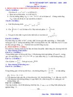
4. Engine Compression
EASUREMENT
FA-.M-
Ignition timing [BTDC/rpm] :
20°± 8°/610
1) After warming up the engine, turn off the ignition
switch .
2) Make sure that the battery is fully charged.
3) Remove all the spark plugs.
3 . Engine Idle Speed
(Refer to "6-1 Spark plug [W4A0]" .)
4) Disconnect connectors from fuel injector .
5) Fully open the throttle valve.
6) Check the starter motor for satisfactory performance
and operation .
A: INSPECTION
1) Before checking idle speed, check the following :
7) Connect compression gauge to spark plug hole .
8) Crank the engine by means of the starter motor, and
read the maximum value on the gauge when the pointer
is steady .
9) Perform at least two measurements per cylinder,
and make sure that the values are correct.
(1) Ensure that air cleaner element is free from clogging, ignition timing is correct, spark plugs are in
good condition, and that hoses are connected properly .
(2) Ensure that CHECK ENGINE light is off.
2) Warm up the engine .
3) Connect "Select Monitor" and measure engine rpm.
(Function model "04")
4) Check idle speed when unloaded (with headlights,
heater fan, rear defroster, radiator fan, air conditioner,
etc . OFF) .
Compression (200 - 300 rpm and fully open throttle) :
Standard
1,177 - 1,422 kPa
(12.0 - 14.5 kg/cm', 171 - 206 psi)
Limit
981 kPa (10 .0 kg/cm', 142 psi)
Difference between cylinders
196 kPa (2 .0 kg/cm2, 28 psi)
Idle speed (No load and gears in N or D position)
610± 100 rpm
r
i
i
Compression gauge
\X
\~
Fig. 1
2
1 /
C2-149
ON-CAR SERVICES
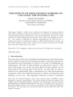
5 . Intake Manifold Vacuum
[05AO] 2-2
i /
A: MEASUREMENT
Vacuum gauge
1 /-
1) Warm up the engine .
2) Disconnect the vacuum hose and install the vacuum
gauge to the hose fitting on the manifold .
3) Keep the engine at the idle speed and read the
vacuum gauge indication .
By observing the gauge needle movement, the internal
condition of the engine can be diagnosed as described
in Table below.
= _,
`
Intake
manifold
til...-
,.~ /1
C2-150
Fig . 2
Vacuum pressure (at idling, A/C "OFF"):
More than 68 .0 kPa (510 mmHg, 20 .08 inHg)
Diagnosis of engine condition by measurement of manifold vacuum
Vacuum gauge indication
1 . Needle is steady but lower than normal position. This tendency
becomes more evident as engine temperature rises .
Possible engine condition
Leakage around air intake system .
2 . When engine speed is reduced slowly from higher speed, needle
stops temporarily when it is lowering or becomes steady above
Back pressure too high, or exhaust muffler clogged .
normal position.
3 . Needle intermittently drops to position lower than normal posiLeakage around cylinder .
tion.
4 . Needle drops suddenly and intermittently from normal position .
Sticky valves.
5 . When engine speed is gradually increased, needle begins to vibrate rapidly at certain speed, and then vibration increases as
engine speed increases .
Weak or broken valve springs .
6 . Needle vibrates above and below normal position in narrow
Defective ignition system or throttle chamber idle adjustment.
range .
3
2-2 [06A1]
ON-CAR SERVICES
6 . Cylinder Head Cover
2. CYLINDER HEAD COVER RH
1) Disconnect ground cable of battery .
2) Remove air intake boots and air cleaner case .
A: REMOVAL
3) Disconnect blow-by hose from cylinder head cover.
4) Remove ignition coil harness clamp from cylinder
head cover.
1 . CYLINDER HEAD COVER LH
5) For subsequent removal operation, follow the same
procedures [steps 5) through 10)] that are outlined
under the "CYLINDER HEAD COVER LH."
1) Disconnect battery cables and remove battery .
2) Disconnect blow-by hose from cylinder head cover .
3) Remove harness clamps.
B: INSTALLATION
Installation is in the reverse order of removal procedures.
Tightening torque :
Cylinder head cover bolts:
4.4 - 5.4 N"m (0 .45 - 0.55 kg-m, 3.3 - 4.0 ft-Ib)
rig . s
4) Remove ignition coils .
(Refer to 6-1 "Ignition coil [W3A0]" .)
5) Disconnect connectors from fuel injectors .
6) Raise the vehicle .
7) Remove under cover.
8) Remove cylinder head cover.
(1) Remove bolts ) through ® while getting under
the car .
fig. 4
(2) Lower the vehicle .
(3) Remove the remaining bolts and the cylinder
head cover.
9) Remove cylinder head cover gasket .
4
ON-CAR SERVICES
7 . Fuel Injector
[08AO] 2-2
8. Collector and Intake Manifold
ASSY
A: REMOVAL
I A: REMOVAL
1) Fuel pressure elimination
(1) Disconnect fuel pump connector.
(2) Start engine .
1) Fuel pressure elimination
(1) Disconnect fuel pump connector.
(2) Start engine .
(3) Run engine until it stalls .
(4) After it stalls, crank starter for approximately 5
seconds and turn ignition switch to "OFF".
2) Disconnect connector from fuel injector .
3) Remove fuel injector cover.
(3) Run engine until it stalls .
(4) After it stalls, crank starter for approximately 5
seconds and turn ignition switch to "OFF".
2) Remove corrector cover.
3) Disconnect throttle cable and cruise control cable
from throttle lever.
4) Remove air intake boots.
5) Disconnect engine harness connectors .
6) Disconnect female connectors of engine harness
from bracket.
Fig . 5
4)
a.
or
b.
Extract while turning fuel injectors.
Do not attempt to pry injectors with a screwdriver
similar tool. Do not pinch injector pin with pliers .
Be careful not to damage O-ring .
c. If injector is difficult to remove with your hand,
remove injector and fuel pipe as a unit, and push
injector out from the back side.
5) To install, reverse order of removal procedures.
C2-155
Fig . 6
7) Disconnect connector from auxiliary air control
va Ive.
8) Disconnect two coolant hoses from throttle body .
(They are located under the throttle body.)
9) Disconnect auxiliary air control valve hose from
throttle body.
10) Disconnect PCV hose from connector PCV.
11) Remove blow-by hose from cylinder head cover
RH .
12) Disconnect EGR control hoses from intake manifold .
13) Remove EGR pipe and cover.
14) Disconnect power steering pump SW connector.
15) Disconnect brake booster hose from intake manifold .
16) Disconnect fuel hoses (delivery, return and evaporation lines) from fuel pipes .
Place a container to catch fuel from fuel hose.
5
2-2 [08130)
ON-CAR SERVICES
B: INSTALLATION
t
Fig . 7
C2-156
17) Remove drive belt cover and drive belts.
(Refer to 1-5 "Drive Belts [01A0]")
18) Disconnect alternator B terminal and connector.
19) Remove bolt securing the alternator harness cover .
20) Remove alternator .
21) Remove A/C belt idler pulley ASSY.
22) Remove all bolts securing the A/C compressor
bracket. Move the A/C compressor and bracket forward
as a unit to facilitate removal of intake manifold mounting bolts .
When moving the compressor and bracket, take care
not to over-stretch the pipes and hoses.
Fig . 10
Installation is in the reverse order of removal procedure .
Observe the following .
1) Remove traces of gasket from the mating surfaces of
the intake manifold and cylinder head before installation .
2) Be sure to use new gaskets.
3) Be careful not to catch hoses or harnesses between
intake manifold and cylinder head .
4) Before installing A/C compressor bracket, apply fluid
packing to thread portion of bolt which indicating arrow
mark in Figure .
1-1g. tr
23) Remove collector and intake manifold ASSY.
Fluid packing
Three bond 1344 or equivalent
Fig. 9
6
ON-CAR SERVICES
[09A2]
2-2
4) Apply SUBARU CRC (004301003) to threaded portion of oxygen (OZ) sensor again, and leave it for one
minute or more .
5) Remove oxygen (OZ) sensor by using socket and
wrench .
When removing, do not force oxygen (OZ) sensor
especially when exhaust pipe is cold ; otherwise it will
damage the exhaust pipe .
2. INSTALLATION
fig .
1) Apply anti-seize compound ("SS-30" made by JETLUBE Inc. in U .S .A . or its equivalent) only to threaded
portion of oxygen (02) sensor to make the next removal
easier .
Never apply anti-seize compound to protector of oxygen (OZ) sensor.
2) By using socket and torque wrench, install oxygen
(OZ) sensor onto front exhaust pipe by tightening it to
the specified torque .
77
9. Oxygen (02) Sensor
A: REPLACEMENT
Oxygen (Oz) sensor is one of the important emission
control parts. Therefore, replace it as follows only when
it is damaged by external force, or if it seems to be out
of order according to troubleshooting etc.
Torque [oxygen (OZ) sensor]:
25 - 34 N"m (2 .5 - 3.5 kg-m, 18 - 25 ft-Ib)
3) Securely connect oxygen (Oz) sensor cord .
1 . REMOVAL
1) Disconnect Oz sensor cord.
2) Apply SUBARU CRC (004301003) or its equivalent to
threaded portion of oxygen (Oz) sensor, and leave it for
one minute or more .
3) Loosen oxygen (O2) sensor by turning it 10 to 40
degrees with special tool (SOCKET: 499990110) and
wrench .
7