Toyota training 973a hi tech update engine technician handbook 01 08 09
Bạn đang xem bản rút gọn của tài liệu. Xem và tải ngay bản đầy đủ của tài liệu tại đây (11.31 MB, 130 trang )
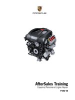
Advanced Engine Control
Hi-Tech Update 973A
Technician Handbook
© 2009 Toyota Motor Sales, U.S.A., Inc.
All rights reserved. This book may not be reproduced or copied, in whole or in part by any means, without the written permission of
Toyota Motor Sales, U.S.A., Inc.
Hi-Tech Update - Advanced Engine Control
Technician Handbook
Table of Contents
Course L973A:Introduction to Advanced Engine Control.............................................................. I
Section 1............................................................................................... 1
Accumulated Emissions FTP........................................................................................................ 2
Emission Levels........................................................................................................................... 3
CAN OBD II Update..................................................................................................................... 4
Interpreting Non-Continuous Readiness Monitor Status and Results.......................................... 5
Readiness Monitor Test Results................................................................................................... 7
Monitor Information -Key ON, Engine OFF.................................................................................. 8
Monitor Information -Engine Running........................................................................................... 9
Readiness Monitor Test Details.................................................................................................. 10
Readiness MonitorTest Details -DTCs Cleared.......................................................................... 11
Permanent DTC......................................................................................................................... 12
Permanent DTC......................................................................................................................... 13
Permanent DTC -Three Trip Clear............................................................................................. 14
Permanent DTC -One Trip Clear................................................................................................ 15
Permanent DTC......................................................................................................................... 16
Calculated Load(Calc Load)...................................................................................................... 17
Vehicle Load -Absolute Load...................................................................................................... 18
Air Flow....................................................................................................................................... 19
MIL ON Data List........................................................................................................................ 20
Section 2 - Misfire............................................................................... 21
Misfire Detection......................................................................................................................... 22
Misfire Data List.......................................................................................................................... 23
continued.................................................................................................................................... 24
Misfire Margin............................................................................................................................. 25
Cat OT MF/FC............................................................................................................................ 26
Cylinder Misfire Rate (Count) & EWMA Misfire.......................................................................... 27
continued.................................................................................................................................... 28
Example of EWMA Misfire Count............................................................................................... 29
Cylinder Speed Data List............................................................................................................ 30
Section 3 - Overview of Sensor Operation....................................... 31
Circuit Configuration of Mass Air Flow Meter............................................................................. 32
A/F Sensor................................................................................................................................. 33
Current and Voltage Characteristic............................................................................................ 34
Technical Training
Hi-Tech Update - Advanced Engine Control
Technician Handbook
A/F Sensor Circuit........................................................................................................................... 35
Comparisons between A/F Sensor and O2 Sensor......................................................................... 36
O2 Sensor Construction.................................................................................................................. 37
CO and O2 Effect on Oxygen Sensor............................................................................................. 38
Super Stability O2 Sensor............................................................................................................... 39
Heater Circuit.................................................................................................................................. 40
Heater Operation............................................................................................................................. 41
Temperature Detection.................................................................................................................... 42
A/F Sensor Circuit........................................................................................................................... 43
A/F Ratio Sensor Pumping Circuit................................................................................................... 44
O2 Sensor Circuit............................................................................................................................ 45
O2 Sensor Temperature and Impedance........................................................................................ 46
Section 4 - Overview of Fuel Injection & Catalytic Converter............ 47
Stoichiometric Lamda Air/Fuel Ratio............................................................................................... 48
Oxygen Storage Capacity (OSC).................................................................................................... 49
Oxygen Storage Capacity (OSC).................................................................................................... 50
Fuel Injection Duration.................................................................................................................... 51
Fuel Trim.......................................................................................................................................... 52
Fuel Trim Response........................................................................................................................ 53
Fuel Trim Diagnosis......................................................................................................................... 54
Fuel Trim Parameters and Values................................................................................................... 55
Fuel Trim Diagnosis Tips................................................................................................................. 57
Relationship between Fuel Injection Duration and MAF Malfunction or Air Leak............................ 58
MAF Air Flow Comparison Check w/Load....................................................................................... 59
MAF Air Flow Comparison Check wo/Load..................................................................................... 60
Airflow-Free VG Check.................................................................................................................... 61
Characteristics of MAF Sensors...................................................................................................... 62
Relationship between Fuel Injection Duration and Fuel System Malfunction.................................. 64
Fuel Trim DTC(s) with Driveability Issues........................................................................................ 65
Section 5 - Catalytic Converter & A/F - O2 Sensor Monitors.............. 66
AF Sensor Pumping Circuit............................................................................................................. 67
AF Sensor Circuit............................................................................................................................ 68
O2 Sensor DTCs by Impedance Detection..................................................................................... 69
O2 Sensor Circuit............................................................................................................................ 70
O2 Sensor Temperature and Impedance..................................................................................... 71
Technical Training
Hi-Tech Update - Advanced Engine Control
Technician Handbook
Active A/F Control Sequence..................................................................................................... 72
Active AF Type............................................................................................................................ 73
Catalyst Monitor ........................................................................................................................ 73
A/F Sensor................................................................................................................................. 74
Active AF Control for AF Sensor Response............................................................................... 75
AF Sensor Response – DTC P2A00, P2A03............................................................................. 76
Active AF Control........................................................................................................................ 77
Active AF Control for O2 Sensor & Catalytic Converter Response............................................ 78
Good O2 Sensor Response Rich to Lean.................................................................................. 79
Good O2 Sensor Response Lean to Rich.................................................................................. 80
Active AF Control Capture – O2 Sensor Response................................................................... 81
P0136 O2 Sensor Circuit Abnormal Voltage.............................................................................. 82
HO2 Sensor Circuit Malfunction................................................................................................. 83
P0137 O2 Sensor Circuit Low Voltage....................................................................................... 84
P0138 O2 Sensor Circuit High Voltage...................................................................................... 85
HO2 Sensor Circuit.................................................................................................................... 86
P0138 Stuck Lean AF Sensor.................................................................................................... 87
Injector Volume & AF Active Tests.............................................................................................. 88
P0138 – Malfunctioning AF Sensor............................................................................................ 89
P0138 – Check for Malfunctioning AF Sensor............................................................................ 90
CO and O2 Effect on Oxygen Sensor........................................................................................ 91
Active AF Control........................................................................................................................ 92
Good Catalyst Response........................................................................................................... 93
Good Catalyst Response........................................................................................................... 94
Active AF Control Capture – Good Catalyst Response.............................................................. 95
Deteriorated Catalyst – Active AF Control.................................................................................. 96
Active AF Control Capture – Failed Catalyst Response............................................................. 97
Catalyst Monitoring System........................................................................................................ 98
Interpreting Catalyst OSC Test Details....................................................................................... 99
Conditioning for Sensor Testing................................................................................................ 100
A/F Ratio Sensor Rationality Check......................................................................................... 101
AF Sensor Stuck Lean P2195.................................................................................................. 102
Drive Pattern............................................................................................................................ 103
Drive Pattern............................................................................................................................ 104
Inspection................................................................................................................................. 105
Heated Oxygen Sensor Voltage Fuel Cut (DTC P0139 and P0159) . ..................................... 107
Technical Training
Hi-Tech Update - Advanced Engine Control
Technician Handbook
Section 6 - EVAP Purge Operation and Monitor............................108
The Way Purge Density Is Learned..........................................................................................109
Purge Control...........................................................................................................................110
EVAP Purge Flow and Purge Density Learn Value.................................................................. 111
Calculation Example of Purge Density Learn Value................................................................. 112
Engine Running Purge Flow Monitor........................................................................................ 113
Knock Control System.............................................................................................................. 114
Knocking Threshold and Fuel Consumption / Engine Output................................................... 115
Resonant Knock Sensor........................................................................................................... 116
Flat Response Knock Sensor................................................................................................... 117
Switching of Knock Detection Filter Frequencies..................................................................... 118
Knock Judgment.......................................................................................................................119
Calculation Example of a Knock Value( renewed every 0.5 seconds approximately)..............120
Learning Ranges......................................................................................................................121
Relationship Among Timing, Knock Correct Learn Value, and Knock Feedback Value...........122
Relationship Among Timing, Knock Correct Learn Value, and Knock Feedback Value...........123
Conditions under which a Knocking Problem Occurs..............................................................124
Unit of MAF..............................................................................................................................125
Technical Training
Hi-Tech Update - Advanced Engine Control
Course 973A:
Introduction to
Advanced Engine Control
Technical Training
Technician Handbook
The technician will be able to determine the condition of advanced
CAN OBDII engine control systems based on verified diagnostic repair
procedures and technical information using: monitored test results,
diagnostic tools, and service literature.
I
Hi-Tech Update - Advanced Engine Control
Technician Handbook
Complete Incomplete Monitor Status
Permanent DTC
Calculated load
Vehicle Load
Atmospheric Pressure
Section 1
Objectives
Technical Training
CAN OBDII Update
•
Determine the condition of a vehicle based on readiness monitor
results, data list parameters, and status of DTCs
•
Clear Permanent DTCs
•
Use new data list parameters for MIL ON diagnosis
1
Hi-Tech Update - Advanced Engine Control
Accumulated Emissions FTP
Technician Handbook
FTP stands for Federal Test Procedure.
Note that emissions are high, particularly NOx, at start up.
Technical Training
2
Hi-Tech Update - Advanced Engine Control
Emission Levels
Technician Handbook
The above emission labels are California labels.
The Federal equivalents are:
Tier 2 Bin 5 = LEV II ULEV
Tier 2 Bin 3 = LEV II SULEV
DTCs are required to set according to the applicable emission
standard.
NMOG stands for Non-methane Organic Gases.
Technical Training
3
Technician Handbook
Hi-Tech Update - Advanced Engine Control
Status 1
Status 2
Misfire
Ready
Available
Fuel System
Ready
Available
Composition Parts
Ready
Available
Catalyst Efficiency
Ready
Complete
Heated Catalyst
Not
Ready
N/A
Evaporative System
Ready
Incomplete
Secondary Air System
Ready
N/A
A/C System
Not
Ready
N/A
O2 Sensor
Ready
Incomplete
Pass
O2 Sensor Heater
Ready
Complete
Pass
EGR
Not
Ready
N/A
Monitor
Interpreting Non-Continuous
Readiness Monitor Status
and Results
Result
Details
Summary
Continuous
Monitor
Monitor ran
and passed
this trip.
Pass
N/A
Fail
Monitor ran
and failed
this trip.
N/A
Monitor has
not finished
testing.
N/A
Monitor
is not
supported.
Readiness Monitors
The goal of the OBD II regulation is to provide the vehicle with an
on-board diagnostic system capable of continuously monitoring the
efficiency of the emission control systems, and to improve diagnosis
and repair efficiency when system failures occur.
On-board tests are performed by the ECM. Two types of on-board test
monitoring are supported: continuous and non-continuous. These are
known as readiness monitors, or simply monitors.
If a readiness monitor fails, DTC(s) specific to the failure(s) are set.
Interpreting Non-Continuous Readiness Monitors Status and
Results
Understanding Readiness Monitors Status and Results will help to
duplicate concerns and verify repairs. The following is a guide to
interpret non-continuous Readiness Monitors Status and Results:
Complete, Pass
If Status 1 (OBD II), Status 2 (CAN OBD II) displays Complete and
Result displays Pass then the monitor completed testing and passed
this trip. Check Test Details for all Readiness Monitors to ensure tests
are passing well within the Min Limit and Max Limit thresholds (see
Readiness Monitors Test Details topic for more information).
Incomplete, Fail
If Status 1 (OBD II), Status 2 (CAN OBD II) displays Incomplete and
Result displays Fail then the monitor ran and failed this trip. An issue
Technical Training
4
Hi-Tech Update - Advanced Engine Control
... continued
Technician Handbook
with the system currently exists and a DTC is present. Diagnosis and
repair is necessary.
Incomplete, Pass
If Status 1 (OBD II), Status 2 (CAN OBD II) displays Incomplete and
Result displays Pass then the monitor has not completed testing
this trip. This is the default setting. This may be due to: the enabling
conditions were not met, the monitor did not complete operating, or
the ECM is withholding judgment. Drive the vehicle per the appropriate
Readiness Monitor Drive Pattern or perform the system check (if
applicable) to run the monitor. Then re-check the Monitor Information
screen.
No Result Information
If Result does not display information, the monitor is not supported and
will not run.
Technical Training
5
Hi-Tech Update - Advanced Engine Control
Technician Handbook
Replace
Readiness Monitor
Test Results
Each readiness monitor runs a series of tests. If one test fails, the
monitor fails and a DTC is set specific to the test.
Test Results can be accessed by clicking the magnifying glass icon
in the Details column of the Monitor Information screen. The Result
column of the Test Results pop-up window will display Pass or Fail,
depending on the result of the test.
The Test Description portion of the Test Results window will display a
description of the specific test that is highlighted.
Technical Training
6
Hi-Tech Update - Advanced Engine Control
Monitor Information Key ON, Engine OFF
Technician Handbook
When the key is first turned ON, and the engine is OFF, the Monitor
Status, Monitor Result, Test Result, and Test Details report on what
happened the during the last key cycle.
This screen capture was taken with key ON, engine OFF after an
overnight soak period.
Technical Training
7
Hi-Tech Update - Advanced Engine Control
Monitor Information Engine Running
Technical Training
Technician Handbook
When the engine has started and is running, the Monitor Status and
Monitor Result will change to Incomplete and Pass. The Test Result
and Test Details will display the last trip values where the monitor ran.
When the monitor runs again, the Test Result and Test Details will
report the results from the latest trip.
8
Hi-Tech Update - Advanced Engine Control
Readiness Monitor
Test Details
Technician Handbook
Test Details displays Min Limit, Max Limit, and Test Value information
from the last trip the monitor ran. This information is also provided in
a graphical representation. The MIN arrow represents the Min Limit,
the MAX arrow represents the Max Limit, and the yellow triangle in the
graph represents the Test Value. Use the Min Limit, Max Limit, and Test
Value information as indicators of a pass or fail condition as failures
may not be easily seen in the graph.
Test Details can be accessed by clicking the magnifying glass icon in
the Details column of the Test Results pop-up window.
Depending on the Status and Result of specific readiness monitors,
Test Details will display information from different trips.
•
•
Technical Training
If Status 2 is Complete and Result is Pass, Test Details will display
information from this trip.
If Status 2 is Incomplete and Result is Pass, Test Details will
display information from the last trip the monitor test completed.
Note
If an intermittent MIL ON condition exists, a Monitor Test Details Test
Value may be crossing over a limit threshold. After a repair attempt has
been made, clear DTCs and run the monitor again. If the same Monitor
Test Details Test Value is within the Min and Max Limit thresholds, the
repair was successful.
Note
The Test Details graph on non Can OBD II vehicles may appear
different from the illustration. Always use the Min Limit, Max Limit, and
Test Value as indicators of Test Details.
Note
If the Test Value was outside of the Min Limit or Max Limit before a
repair, and is within the Min Limit and Max Limit after a repair, the
repair was probably successful.
9
Hi-Tech Update - Advanced Engine Control
Readiness Monitor
Test Details DTCs Cleared
Technician Handbook
If a readiness monitor test has not completed testing since DTC(s)
were cleared, Test Details will display incomplete information. Min
Limit, Max Limit, and Test Value will display incomplete values. The
graph will be all red with the MIN and MAX arrows and the yellow
triangle aligned along the center line.
If the readiness monitor Test Details displays incomplete information,
drive the vehicle per the appropriate Readiness Monitor Drive Pattern
or perform the system check (if applicable) to run the monitor. Then,
re-check the Monitor Information screen.
Note
Technical Training
The Test Details graph on older vehicles may appear different from
the illustration. Always use the Min Limit, Max Limit, and Test Value as
indicators of Test Details.
10
Hi-Tech Update - Advanced Engine Control
Technician Handbook
Permanent DTCs are trouble codes that are stored in the ECM
when continuous and non-continuous monitors fail. Permanent
DTCs are set in conjunction with Current and History DTCs.
Permanent DTCs can not be cleared using the Clear DTCs
function on the Scantool.
Instead, Permanent DTCs are cleared by two methods.
1) When the ECM monitor completes and passes three
consecutive trips
2) After clearing DTCs with a scantool, the monitor passes one
trip.
Permanent DTC
Permanent DTCs are trouble codes that are stored in the ECM when
continuous and non-continuous monitors fail. Permanent DTCs are set
in conjunction with Current and History DTCs.
Permanent DTCs can not be cleared using the Clear DTCs function
on the ScanTool. Instead, Permanent DTCs are cleared when the ECM
monitor completes and passes three consecutive trips, OR
After clearing DTCs, the monitor passes one trip.
When cleared by a ScanTool, the MIL is OFF. The vehicle must driven
to clear the permanent DTC.
Technical Training
11
Hi-Tech Update - Advanced Engine Control
Technician Handbook
Permanent DTC
Technical Training
12
Hi-Tech Update - Advanced Engine Control
Permanent DTC Three Trip Clear
Technical Training
Technician Handbook
Permanent DTC will clear after three monitored, good trips.
13
Hi-Tech Update - Advanced Engine Control
Permanent DTC One Trip Clear
Technician Handbook
When DTCs are cleared, the MIL is turned off.
Look up the confirmation drive pattern and the universal trip drive pattern. Operate and drive the vehicle accordingly.
You must drive after clearing DTCs.
Obtaining a normal judgment and performing a universal trip driving
pattern can be done in the same driving cycle or in different driving
cycles.
It is unnecessary to obtain a normal judgment if the DTCs are for misfire or the fuel system.
Technical Training
14
Hi-Tech Update - Advanced Engine Control
Permanent DTC
Technical Training
Technician Handbook
Drive this pattern to clear permanent DTC after using scantool.
15
Hi-Tech Update - Advanced Engine Control
Calculated Load
(Calc Load)
Technician Handbook
The Calc Load data list is the same in Data List and generic OBD II
data list. The data list item is designated as PID $04.
Characteristics are:
•
Reaches 1.0 (100%) at any altitude, temperature, or RPM
•
Indicates peak available torque (at that RPM)
•
Linearly correlated with intake manifold pressure (engine vacuum)
As intake manifold pressure increases, the calculated load value
increases.
Technical Training
16
Hi-Tech Update - Advanced Engine Control
Vehicle Load Absolute Load
Technical Training
Technician Handbook
Characteristics of LOAD_ABS are:
•
Ranges 0 to approximately 0.95 (95%) for naturally aspirated
engines
•
Linearly correlated with engine indicated and brake torque.
•
Peak value of LOAD_ABS correlates with volumetric efficiency at
WOT
17
Hi-Tech Update - Advanced Engine Control
Technician Handbook
Characteristics of Air Flow:
Increases with horsepower
Maximum Air Flow (g/sec) = Maximum Horsepower
Restrictions effect horsepower and torque
Restrictions have very little effect on fuel economy
Air Flow
Air flow correlates with horsepower: more air flow equals more
horsepower.
Multiplying 1.32 times MAF g/sec will provide the approximate
horsepower the engine is producing. This can be useful when talking to
customers about fuel economy. More horsepower will consume more
fuel.
Technical Training
18
Hi-Tech Update - Advanced Engine Control
Technician Handbook
MIL ON Data List
Technical Training
19