toyota training course t874 engine control systems II ch08
Bạn đang xem bản rút gọn của tài liệu. Xem và tải ngay bản đầy đủ của tài liệu tại đây (3.62 MB, 14 trang )
Section 8
Air Induction Systems
Slide 109
L852f809
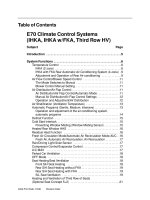
Electronic Throttle Without an Electronic Throttle Control System, the throttle valve position
Control System and opening rate is controlled directly by the driver through a mechanical
Overview system (accelerator cable or linkage). The ECM controls engine idle
speed with the Idle Air Control Valve (IACV). Under command from
the ECM, the IACV allows a certain amount of air to bypass the closed
throttle valve. Use of an IACV allows idle speed to be stabilized under
varying engine loads and, in some applications, provides cold fast idle.
Electronic Throttle Control System-intelligent (ETCS-i) gives the ECM
complete control of the throttle valve position and opening rate.
ETCS-i controls throttle operation based on driver input and other vehicle
operating conditions. ETCS-i allows systems such as Vehicle Skid
Control (VSC) to adjust throttle valve angle to help maintain traction. A
“limp home” feature allows the vehicle to be driven at reduced speed if
the system malfunctions.
Toyota Engine Control Systems I
Course 852
97
ETCS-i Operation
Air Induction Systems
Slide 110
208EG44/241EG28
Operation
In linkless ETCS-i, there is no mechanical cable connection between the
driver’s foot and the throttle body. Major system components include:
•Accelerator Pedal Position Sensor (APPS): The APPS is mounted
at the accelerator pedal. As the driver moves the accelerator pedal,
the APPS signal voltage changes to indicate pedal position. There
are two voltage output signals from the APPS. The ECM uses these
two signals to calculate the desired throttle valve angle. Also, by
using two signals the ECM is able to compare and detect if there is
anything wrong with APPS performance.
•Throttle Position Sensor (TPS): The TPS detects the actual angle
of the throttle valve. This system uses a dual-output TPS.
•Throttle Control Motor: The throttle control motor is a DC motor
controlled by the ECM. The ECM controls the direction and the
amperage of the current through the motor. The circuit is pulsewidth
modulated (duty ratio cycle regulated). If there is a malfunction, the
ECM shuts the circuit OFF and the return springs close the throttle
valve. The ECM will turn the motor OFF if there is not enough or
too much amperage in the motor circuit. Unlike the link type, there
is no magnetic clutch between the throttle control motor and the
throttle valve.
•Fail-Safe: If ETCS-i malfunctions, the MIL will illuminate to alert
the driver. If the failure is in either one of the APPS or TPS signals,
the ECM will attempt to use the second signal to continue limited
electronic throttle control. If all four of these signals malfunction,
the vehicle can be operated only at idle speed (there is no “limp
mode” lever). ISC and cruise control systems will not operate.
98
TOYOTA Technical Training
Air Induction Systems
Variable Valve Timing Systems (VVT-i)
Slide 111
T852f285/T852f286
Variable Valve Timing Without variable valve timing, engine valve timing is a compromise
Systems (VVT-i) between the needs to produce maximum torque (horsepower) at
low to medium speeds, idle stability, fuel economy, low emissions,
and maximum horsepower output. Continuously adjusting when the
valves open and close, called variable valve timing, yields significant
improvements in all these areas. The ECM, according to driving
conditions such as engine speed and load, will advance or retard the
camshaft, changing when the valves open and close. This system is called
the Variable Valve Timing-intelligent (VVT-i) system.
There are two types of VVT-i:
•VVT-i controls intake valve timing only (as shown).
•Dual VVT-i controls both intake and exhaust valve timing.
Both systems use an ECM-controlled oil pressure system to alter camshaft
position.
Toyota Engine Control Systems I
Course 852
99
Benefits of VVT-i
Air Induction Systems
Slide 112
Effects of VVT-i
VVT-i provides a variety of benefits:
•Smooth Idle: At idle RPM, valve overlap is eliminated by retarding
the camshaft. There is no blowback of exhaust gases to the intake side.
Combustion is more stable because of the clean air/fuel mixture.
•Torque Improvement in Low to Medium Speed Range: In the low
to medium speed range with a heavy load, the camshaft is advanced,
increasing the valve overlap. This has two effects. First, the exhaust
gases help pull in the intake mixture. Second, by closing the intake
valve early, the air/fuel mixture taken into the cylinder is not discharged.
This improves volumetric efficiency and increases torque (and therefore
horsepower) in the low and midrange RPM range.
•EGR Effect: VVT-i eliminates the need for an Exhaust Gas
Recirculation (EGR) valve by increasing valve overlap.
•Better Fuel Economy: A VVT-i equipped engine is more efficient
and provides better fuel economy from a variety of factors. Without
VVT-i, the engine would have to be larger and heavier to produce
the same horsepower. Smaller pistons, connecting rods, and
crankshaft reduce friction and mechanical losses. A lighter engine
improves vehicle fuel economy. Also, it takes less energy to move
the piston downward on the intake stroke.
•Improved Emission Control Performance: VVT-i increases the
valve overlap, creating an internal EGR effect. Another benefit
is that hydrocarbons (HCs) are reduced. Some of the unburned
air/fuel mixture from the previous cycle returns to the cylinder for
combustion. Finally, CO2 is reduced because of the decrease in fuel
consumption.
100
TOYOTA Technical Training
VVT-i Construction and Diagnosis
Air Induction Systems
Slide 113
T852f296/T852f297
Construction
VVT-i uses the crankshaft position sensor and Variable Valve Timing
(VVT) sensors (camshaft position sensor) to measure the amount of
camshaft movement. This feedback is necessary for the ECM to know
how much and which direction to move the camshaft, and for diagnosis.
A continuously variable valve timing mechanism, called a controller or
actuator, is used to adjust the camshaft from one end of its adjustment
range to the other.
A camshaft timing Oil Control Valve (OCV), controlled by the ECM,
directs engine oil pressure to the advance or retard side of the VVT-i
controller. Two types of controller have been used: helical and vane. All
Dual VVT-i systems use vane type controllers.
Diagnosis
When trying to determine the cause of a VVT system issue, check the
Freeze Frame data and duplicate the conditions. Use the Technical
Information System (TIS) for Repair Manual (RM) and Electrical Wiring
Diagram (EWD) information, and look for applicable Technical Service
Bulletins (TSBs).
Active Tests
Active tests can be performed to check the VVT system. Different active
tests will be available depending on the VVT system. Typically, when
the valve timing is changed at idle with an active test, the engine will run
rough or may die. Refer to the Repair Manual for the proper VVT active
test response and diagnostic procedure.
NOTE: Check the vehicle service history. If the vehicle has been repaired in the
past, check for improperly installed timing belts, components, etc.
Toyota Engine Control Systems I
Course 852
101
VVT-i OCV
Air Induction Systems
Slide 114
T852f288/T852f289
Oil Control Valves The Oil Control Valve (OCV) is controlled by the ECM to direct engine
oil pressure to the advance or retard side of the VVT-i controller. The
OCV spool valve position is determined by a varying magnetic field
strength opposing a constant spring strength:
•Advance: To advance timing, the ECM increases the pulsewidth (duty
ratio). This strengthens the magnetic field, overcoming spring pressure
and moving the spool valve to send more oil to the advance side.
•Retard: To retard the timing, the ECM decreases the pulsewidth.
Spring pressure overcomes the weaker magnetic field and the spool
valve moves toward the retard position.
•Hold: When the camshaft is in the desired position, the ECM sends
a pulsewidth that moves the spool valve to the hold position. In the
hold position, the oil is trapped in the controller, maintaining the
desired camshaft position. When the engine is stopped, the spring
pushes the spool valve to the most retarded position (intake) or the
most advanced position (exhaust).
102
TOYOTA Technical Training
Air Induction Systems
VVT-i Controller (Helical)
Slide 115
T852f293/T852f294/T852f295
Controller (Helical)
The helical VVT-i controller has an outer gear driven by the timing belt,
an inner gear affixed to the camshaft, and a movable piston that is placed
between the outer gear and inner gear. As the piston moves laterally
(axially), the helical splines on the piston and inner gear force the
camshaft to move in relation to the timing gear.
Oil pressure from the OCV is directed to one or the other side of the
piston to advance, retard, or maintain valve timing:
•Advance: When the ECM commands the OCV to advance timing,
hydraulic pressure is applied from the left side of the piston, moving
the piston to the right. The twist in the helical splines on the inside
diameter of the piston causes the intake camshaft to rotate in the
advance direction in relation to the camshaft timing pulley.
•Retard: When the ECM commands the OCV to retard timing,
hydraulic pressure is applied to the right side of the piston, moving
the piston to the left. The camshaft rotates in the retard direction.
•Hold: To hold the desired camshaft position, the OCV shuts off the
oil passages. This maintains the hydraulic pressure on both sides of
the piston, and camshaft position does not change.
Toyota Engine Control Systems I
Course 852
103
VVT-i Controller (Vane)
Air Induction Systems
Slide 116
T852f298/T852f299/T852f300/T852f301/T852f302/T852f303
Controller (Vane)
Oil pressure from the OCV is directed to one or the other vane chamber
to advance, retard, or maintain valve timing:
•Advance: When the ECM commands the OCV to advance timing,
hydraulic pressure is applied to the timing advance side vane
chamber. The camshaft rotates in the advance direction.
•Retard: When the ECM commands the OCV to retard timing,
hydraulic pressure is applied to the timing retard side vane chamber.
The camshaft rotates in the retard direction.
•Hold: To hold the desired camshaft position, the OCV shuts off the
oil passages. This maintains the hydraulic pressure in both vane
chambers, and camshaft position does not change.
NOTE: Special care should be taken when installing VVT-i controllers. Always
refer to the Repair Manual for vehicle specific procedures.
104
TOYOTA Technical Training
Air Induction Systems
Dual VVT-i Operation
Slide 117
Dual VVT-i Operation Dual VVT-i uses OCVs and vane controllers to set both intake and
exhaust camshaft timing. Separate control of intake and exhaust valve
timing allows varying amounts of valve overlap based on engine
operating conditions:
•No overlap: There is no overlap during engine starting/stopping,
idling, low temperature, or light load operation. Blowback is
prevented on the intake side for improved starting, stabilized RPM,
and improved fuel economy.
•Maximum overlap: There is maximum overlap during medium
load and low to medium speed operation with heavy load. Overlap
is maximized to reduce pumping loss and improve volumetric
efficiency for increased torque, better emission control, and
improved fuel economy.
•Moderate overlap: There is moderate overlap during high speed
operation. Overlap is moderate to improve volumetric efficiency for
increased power output.
Toyota Engine Control Systems I
Course 852
105
Acoustic Control Induction System (ACIS)
Air Induction Systems
Slide 118
T852f316
Acoustic Control The Acoustic Control Induction System (ACIS) improves torque
Induction System throughout the engine speed range (especially at low speeds) by changing
(ACIS) the intake manifold length in stages. The ECM commands intake air
control valve(s) to change the length of the intake manifold based on
engine speed and throttle valve opening.
ACIS is tuned for each type of engine. Vacuum stored in the vacuum
chamber is applied to the intake air control valve through the VSV. The
VSV is switched ON and OFF by the ECM. The intake air control valve
is switched according to engine speed and load.
The air flow in the intake pipe pulsates due to opening and closing of the
engine intake valves. When an intake valve closes, the air near the valve
is compressed by inertia. This compressed air pushes off the intake valve
at high speed toward the intake chamber. If the intake manifold length
and intake chamber shape are set to cause the compressed air to return
to an engine intake valve during the intake stroke, the intake air volume
is increased, improving volumetric efficiency. This is called the intake
"inertia effect", and it improves torque and horsepower.
106
TOYOTA Technical Training
Air Induction Systems
Exhaust Gas Recirculation (EGR)
Slide 120
T852f250
Exhaust Gas The Exhaust Gas Recirculation (EGR) system is used for reducing oxides
Recirculation (EGR) of nitrogen (NOx) and for engine knock control. Recirculating a controlled
amount of exhaust gases into the intake air/fuel mixture lowers combustion
temperature and pressure. This, in turn, reduces the amount of NOx emission,
helps prevent engine knock, and allows for more advanced ignition timing.
Under the following conditions, EGR is cut to maintain driveability.
•Before the engine is warmed up
•During deceleration (throttle valve closed)
•Light engine load (amount of intake air very small)
•High engine RPM
•Wide open throttle (WOT)
•Engine idling
The EGR valve opens and closes the passage between the exhaust manifold
and intake manifold. Vacuum is used to move the EGR valve. Inside the
vacuum actuated EGR valve is a valve, diaphragm, and spring. When vacuum
is applied to the diaphragm, it lifts the valve off its seat, allowing exhaust
gases into the intake air stream. When vacuum is removed, the spring forces
the diaphragm and valve downward, closing the exhaust passage.
For proper engine operation, the EGR valve must open to the proper
height, and when closed seal the intake manifold from exhaust gases.
Some EGR valves are water cooled to cool the exhaust gases. Cooling
the exhaust gases increases their effectiveness in reducing NOx and
controlling engine knock.
CAUTION: The EGR valve can get very hot. Handle with care.
Toyota Engine Control Systems I
Course 852
107
EGR Operation (Cutoff Control)
Air Induction Systems
Slide 121
T852f251
EGR Operation
(Cutoff Control)
In the Cutoff Control EGR system, the amount of exhaust gas to be
recirculated is controlled by the EGR vacuum modulator. The EGR
vacuum modulator compensates for changes in engine vacuum and
exhaust backpressure due to changes in throttle position and engine load.
The EGR vacuum modulator provides vacuum to the EGR valve so that
it opens to the correct height regardless of variations in engine vacuum or
exhaust backpressure. The ECM controls the EGR VSV to allow or block
this modulated vacuum from reaching the EGR valve. When the ECM
turns the VSV ON, vacuum is blocked from reaching the EGR valve.
When the ECM turns the VSV OFF, vacuum is allowed to reach the EGR
valve through the EGR vacuum modulator.
The ECM uses the EGR temperature sensor signal for EGR operation
detection. If the temperature is too low (cold) there is little or no flow. If
the temperature is high (hot) when the EGR valve is supposed to be OFF,
the EGR valve is leaking.
108
TOYOTA Technical Training
Air Induction Systems
EGR Operation (Constant Vacuum)
Slide 122
T852f255
EGR Operation
(Constant Vacuum)
This type of ECM controlled EGR system uses a Vacuum Control Valve
(VCV), an EGR VSV, and an EGR valve position sensor to regulate
exhaust gas flow.
The VCV regulates the intake manifold vacuum applied to the VSV to a
constant level.
The EGR valve position sensor is a potentiometer sensor mounted on the
EGR valve. As the EGR valve opens, the voltage signal of the EGR valve
position sensor increases.
The ECM uses the EGR valve position sensor signal to control EGR
valve position height. EGR valve height is controlled by the strength
of the vacuum signal, and the ECM controls vacuum signal strength by
varying the pulsewidth signal sent to the EGR VSV. If greater EGR flow
is needed, the ECM increases the pulsewidth signal to the EGR VSV. This
applies more vacuum to the EGR valve.
The ECM uses the EGR temperature sensor signal for EGR operation
detection. If the temperature is too low (cold) there is little or no flow. If
the temperature is high (hot) when the EGR valve is supposed to be OFF,
the EGR valve is leaking.
Toyota Engine Control Systems I
Course 852
109
Air Induction Systems
110
TOYOTA Technical Training