Bài đọc hiều tiếng anh ô tô
Bạn đang xem bản rút gọn của tài liệu. Xem và tải ngay bản đầy đủ của tài liệu tại đây (275.55 KB, 7 trang )
General working principle
The purpose of a gasoline car engine is to convert gasoline into motion so that your car can
move. Currently the easiest way to create motion from gasoline is to burn the gasoline inside an
engine. Therefore, a car engine is an internal combustion engine, combustion takes place
internally.
There are different kinds of internal combustion engines. Diesel engines are one form and
Gasoline engines are another. Each has its own advantages and disadvantages.
A steam engine in old-fashioned trains and steam boats is the best example of an external
combustion engine. The fuel (coal, wood, oil, whatever) in a steam engine burns outside the
engine to create steam, and the steam creates motion inside the engine.
Internal combustion is a lot more efficient (takes less fuel per mile) than external combustion,
plus an internal combustion engine is a lot smaller than an equivalent external combustion
engine.
One good example for internal combustion is an old Revolutionary War cannon. You have
probably seen where the soldiers load the cannon with gun powder and a cannon ball and light
it. The generated heat and gases force the cannon ball to be pushed out the barrel at very high
speed.
The cannon uses the basic principle behind any reciprocating internal combustion engine: If you
put a tiny amount of high-energy fuel (like gasoline) in a small, enclosed space and ignite it,
energy is released in the form of expanding gas.
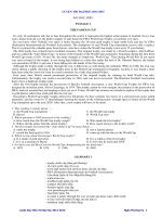
4-stroke working cycle
Reciprocating engines are classified into two types, the 2-cycle and the 4-cycle type. The
principle of the reciprocal engine is that the mixture of the air and the gasoline are injected into
the cylinder, the mixture is combusted, the combustion force drives the piston in reciprocal
movement, and the reciprocal movement is changed to the rotational movement by the
crankshaft. Almost all cars currently use what is called a four-stroke combustion cycle to convert
fuel into motion. The four-stroke working cycle is also known as the Otto cycle, in honor of
Nikolaus Otto, who invented it in 1867. The horizontal axis of the graph represents the pressure
inside the combustion chamber and the vertical axis represents the volume of the combustion
chamber.
The four strokes are:
1. Intake stroke (A-B):
The piston starts at the top, the intake valve opens, and the piston
moves down. On gasoline engines the engine take in a cylinder-full of
air and gasoline. On Diesel engines only air is drawn into the
combustion chamber.
2. Compression stroke (B-C):
The piston moves back up to compress the fuel/air mixture, so that the
pressure and temperature is increased. The fuel is vaporized by the
compressive heat of the air. The compression ratio on a gasoline
engine is around 10:1, on a Diesel engine it is around 25:1
3. Ignition/ Combustion stroke (C-D):
The piston reaches the top of its stroke, also referred to as Top Dead
Center (TDC). On gasoline engines the ignition will be performed by
the electric spark generated from the spark plug. On diesel engines
fuel is injected into the combustion chamber just before the piston
reaches TDC and the air fuel mixture is ignited by the heat of
compression. The mixture is not fully combusted at the ignition time.
As a result there is some time lag from the ignition to the maximum
pressure that arises inside the combustion chamber. The air/fuel
mixture in the cylinder explodes, driving the piston down.
4. Exhaust stroke (D-E):
Once the piston hits the bottom of its stroke, also referred to a Bottom
Dead Center (BDC), the exhaust valve opens and the exhaust leaves
the cylinder to go out the tail pipe.
Now the engine is ready for the next cycle, so it intakes another
charge of air and gas.
Engine classification
Engines can be classified as follows:
Working Principle: Gasoline (spark ignition engine) or Diesel (compression ignition
engine)
Cooling: Water or Air cooled
Stroke cycle operation: Two or four stroke
Valve mechanism: Overhead Camshaft (OHC) or Overhead Valve (OHV) design
Number of cylinders: Engines can have 4,6, or 8 cylinders.
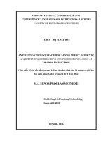
Array style of cylinders: In a multi-cylinder engine, the cylinders usually are arranged in
one of three ways, known as inline, V or opposed.
The in-line type engine has the cylinder in sequentially arrayed. In the in-line type, the structure
of the cylinder block is very simple and the cylinder head is one unit, so the engine is light and
compact. 3, 4, 5 or 6 cylinder can usually be found on the in line engine. The V-type engine is
usually available with 6,8,10 or 12 cylinders. They are usually installed at large vehicles or
sports cars. The opposed engine is available with s 6, 8, 10 or 12 cylinders. Due to the low
center of gravity it is mainly applied to sports vehicles.
Arrangement on vehicle
The final application of the engine can be lengthwise or transverse, either in the front, middle or
rear of the vehicle. For example, the Front engine Rear drive type car having the engine at front
(lengthwise) and driving the rear wheels via a prop shaft attached to the transmission. Front
engine (transverse) Front drive is mainly applied on small cars, because the rotation axis of the
engine and the driving axis are arranged parallel, thus reducing the room required for
installation.
Engines installed at the middle of a car main focus on the performance rather than the
convenience of the passenger so that it is mainly applied to the sports cars.