DSpace at VNU: Electrothermal Microgripper With Large Jaw Displacement and Integrated Force Sensors
Bạn đang xem bản rút gọn của tài liệu. Xem và tải ngay bản đầy đủ của tài liệu tại đây (998.11 KB, 10 trang )
1546
JOURNAL OF MICROELECTROMECHANICAL SYSTEMS, VOL. 17, NO. 6, DECEMBER 2008
Electrothermal Microgripper With Large Jaw
Displacement and Integrated Force Sensors
Trinh Chu Duc, Gih-Keong Lau, J. Fredrik Creemer, Member, IEEE, and Pasqualina M. Sarro, Fellow, IEEE
Abstract—The novel design of a sensing microgripper based
on silicon-polymer electrothermal actuators and piezoresistive
force-sensing cantilever beams is presented. The actuator consists
of a silicon comb structure with an aluminum heater on top and
filled polymer in between the comb fingers. The sensor consists of a
silicon cantilever with sensing piezoresistors on top. A microgripper jaw displacement up to 32 µm at a 4.5-V applied voltage is
measured. The maximum average temperature change is 176 ◦ C.
The output voltage of the piezoresistive sensing cantilever is up to
49 mV at the maximum jaw displacement. The measured force
sensitivity is up to 1.7 V/N with a corresponding displacement
sensitivity of 1.5 kV/m. Minimum detectable displacement of 1 nm
and minimum detectable force of 770 nN are estimated. This sensing microgripper can potentially be used in automatic manipulation systems in microassembly and microrobotics.
[2008-0064]
Index Terms—Electrothermal actuator, microgripper, piezoresistive sensor, polymeric actuator, sensing microgripper.
I. I NTRODUCTION
W
HEN manipulating micro-objects, the dexterity, accuracy, and speed are considerably improved when the
force on the objects can be sensed and controlled in real time
[1]. The development of such miniaturized manipulators is of
great interest for operating on living cells, minimally invasive
surgery, microrobotics, and microassembly.
The manipulation of micro-objects with traditional microgrippers without a built-in force sensor normally requires a
camera to obtain visual feedback. This approach results in a
2-D image. The depth perception of the contact between the
manipulating tool and the object being manipulated is lost,
making it difficult to identify the position of the tool [1].
Moreover, only displacements and not force can be detected.
A microgripper with a built-in force sensor can address this
limitation and, thus, is suitable for holding objects firmly, while
avoiding any squeezing of delicate objects.
Manuscript received March 12, 2008; revised July 22, 2008. Current version
published December 4, 2008. Subject Editor C.-J. Kim.
T. Chu Duc is with the Faculty of Electronics and Telecommunication,
College of Technology, Vietnam National University, Hanoi, Vietnam (e-mail:
).
G.-K. Lau is with the School of Mechanical and Aerospace Engineering, Nanyang Technological University, Singapore 639798 (e-mail: mgkLau@
ntu.edu.sg).
J. F. Creemer and P. M. Sarro are with the Electronic Components, Technology and Materials Laboratory, Delft Institute of Microsystems and Nanoelectronics, Delft University of Technology, 2628 CT Delft, The Netherlands
(e-mail: ; ).
Color versions of one or more of the figures in this paper are available online
at .
Digital Object Identifier 10.1109/JMEMS.2008.2007268
In recent years, several designs of microgrippers with force
feedback have been demonstrated. A force-sensing microgripper for minimally invasive surgery application [2] employs
piezoelectric actuation with strain gauge sensors on the side
wall of the structure. It is capable of actuating at high frequency (hundreds of hertz) with very high driving voltage.
In [3], a similar design device was presented. It uses electromagnetic actuation and piezoelectric force sensing. It generates large displacements at low voltage and a linear sensing
output. However, the main limitations of the aforementioned
devices are the incompatibility with CMOS technology and
rather large dimensions. Electrothermal actuators with builtin piezoresistive force sensors were presented in [4] and [5].
The jaw displacements and output sensing voltages are rather
small, limiting their application. An electrostatic microgripper
with an integrated capacitive force sensor is presented in [6].
This device is capable of motion up to 100 μm with a force
sensitivity of 4.41 kV/m and a corresponding 70-nN forcesensing resolution. However, the limitations of this device are
its large size and complicated electronic circuit required by the
electrostatic method used.
This paper presents a novel sensing microgripper based
on silicon-polymer electrothermal actuators [7] and piezoresistive force-sensing cantilever beams [8]. The proposed
sensing microgripper is capable of providing a large jaw
displacement and output sensing voltage. This device is capable of monitoring the jaw displacement and resulting applied force. The device is made on silicon-on-insulator (SOI)
wafers with a fabrication process compatible with CMOS
technology.
II. D ESIGN
In Fig. 1, a schematic drawing of the sensing microgripper
is shown. The structure is based on the combination of siliconpolymer electrothermal microactuators and piezoresistive lateral force-sensing cantilever beams. When the electrothermal
actuator is activated, the microgripper’s arm and also the
sensing cantilever are bent. This causes a difference in the
longitudinal stress on the opposite sides of the cantilever. This
changes the resistance values of the sensing piezoresistors on
the cantilever. The displacement of the microgripper jaws can
be monitored by the output voltage of the Wheatstone bridge of
the piezoresistive sensing cantilever beam. The contact force
between the microgripper jaws and clamped object is then
determined from the displacement and stiffness of the microgripper arm [9].
1057-7157/$25.00 © 2008 IEEE
CHU DUC et al.: MICROGRIPPER WITH LARGE JAW DISPLACEMENT AND INTEGRATED FORCE SENSORS
1547
TABLE I
GEOMETRY OF THE SENSING MICROGRIPPER
Fig. 1.
Schematic drawing of the sensing microgripper.
[10]–[12]. When the heater is activated, the generated heat is
efficiently transferred to the surrounding polymer through the
deep silicon comb finger structure that has a large interface area
with the polymer layer. The polymer layers expand along the
lateral direction causing a bending displacement of the actuator arm.
As the polymer, we have selected SU8 2002 (Microchem
Inc.). Its low viscosity (7.5 cSt) is specifically developed to
produce thin layers (2–3 μm) [13] and is low enough for the
void-free filling of the 3-μm-wide trenches. The main properties of the materials used are summarized in Table II. This
electrothermal microgripper can be actuated with a low driving
voltage, power consumption, and operating temperature.
Fig. 2. Front- and cross-side views of a sensing microgripper arm with
geometry symbols and parameters.
B. Thermomechanical Finite Element Modeling
Fig. 2 shows the front- and cross-side views of the sensing
microgripper design. The geometrical parameters are given in
Table I.
A. Silicon-Polymer Electrothermal Microactuator
The microgripper is designed in normally open operating
mode. Each actuator has a silicon comb finger structure with
the aluminum metal heater on top. A thin layer of silicon nitride
is employed as the electrical isolation between the aluminum
structure and the silicon substrate. The gaps between the silicon comb fingers are filled with SU8 polymer (see Fig. 1).
Each actuator consists of 41 silicon comb fingers with SU8
polymer layers in between. The silicon fingers are 6 μm wide,
75 μm long, and 30 μm thick. The SU8 polymer layers are
3 μm wide. The length/width (Lcomb /HSU8 ) and height/width
(T /HSU8 ) ratios of the polymer layer are 25 and 10, respectively (see Table I). These values, being greater or equal to
10, satisfy the prerequisite for the maximum constraint effect
To simulate the performance of the proposed sensing
microgripper, a finite element modeling software COMSOL
(Comsol Inc.) is used. The related material properties (see
Table II) are assumed to be temperature independent. The 3-D
thermomechanical model is used to determine the “steadystate” temperature distribution within the actuator and sensing
cantilever structures. The thermal expansion and resulting
actuator displacement are computed based on the temperature
results [12].
The actuator is assumed to be immersed in air. The silicon
comb structure acts as heat source and the rest of the gripper
arm as a heat sink. The substrate is assumed to be thermally
grounded, and therefore, the temperature of the device anchors
is fixed and equal to the ambient temperature. The heat dissipation through convection and radiation into the atmosphere can
be ignored in comparison to the heat loss due to conduction in
the actuator anchors when the working temperature is below
500 K [23]–[25]. More details on the simulations can be found
in [7] and [12].
1548
JOURNAL OF MICROELECTROMECHANICAL SYSTEMS, VOL. 17, NO. 6, DECEMBER 2008
TABLE II
PROPERTIES OF SILICON, ALUMINUM, AND SU8
Fig. 3. Steady-state thermal profile on actuator and cantilever.
Fig. 3 shows the simulated steady-state temperature profile
along the line through the middle point of all comb fingers
of the actuator and sensing cantilever when the microgripper
jaw displacement is 25 μm at the applied voltage of 4.5 V. The
maximum temperature change of 195 ◦ C in the actuator occurs
approximately at 300 μm from the anchor along its longitudinal
axis. The temperature in the cantilever changes linearly from
ambient temperature at the anchor to 189 ◦ C at its tip. The
simulated temperature at the microgripper jaws is 190 ◦ C.
The average working temperature in the electrothermal actuator is estimated from the aforementioned simulated temperature at the middle point of all comb fingers. Fig. 4 shows the
simulated microgripper jaw displacement versus the average
temperature change and also the maximum temperature change.
The maximum displacement of the two microgripper jaws
djaws is 25 μm at the average temperature change of 150 ◦ C,
corresponding to a maximum temperature change of 195 ◦ C
(see Fig. 3). The displacement of the sensing cantilever dcan
is also simulated and shown in Fig. 4. The maximum sensing
cantilever tip displacement is 9.3 μm when the microgripper
jaw displacement is 25 μm (see Figs. 1 and 4). The initial gap
between the two jaws of the microgripper is designed to be
40 μm. Therefore, this proposed sensing microgripper is expected to be capable of gripping micro-objects with a diameter
of 15–40 μm.
The simulated static lateral stiffness Kl of the sensing microgripper arms is 1.8 kN/m. This value is obtained using a mechanical model with an external lateral load at the microgripper
jaws. The maximum output force of this microgripper is calcu-
Fig. 4. Simulated microgripper jaw displacement and the cantilever tip displacement versus the average working temperature change and maximum
temperature change.
lated through the maximum displacement of the microgripper
arm and its stiffness of 22.5 mN.
C. Piezoresistive Force-Sensing Cantilever Beam
The force sensor design is based on the lateral force-sensing
piezoresistive cantilever beam [8], [26]. The four piezoresistors
are located on the cantilever beam structure and connected to
create a Wheatstone bridge (see Figs. 1 and 2). The piezoresistors are aligned along the [110] direction in the (001) crystal
plane of the silicon wafer. The resistor pair located on the
cantilever are stress-sensing resistors. When the electrothermal
actuator is activated, the cantilever beam is bent parallel to the
wafer surface. Therefore, the differential change of resistance
occurs on the two resistors RS1 and RS2 (see Fig. 2). The resistance change of the piezoresistors depends on the displacement
u of the tip of the cantilever beam and is given by [8]
−πl Klcan
ΔR
=
R
Il
L−
Ls
2
(1)
where L is the length of the cantilever, Ls is the length of
the piezoresistors, z is the distance from the resistor to the
neutral plane of the cantilever, πl is the longitudinal piezoresistive coefficient of the resistors (in this paper, we assume
the values of room-temperature first-order piezoresistive coeffi3
T is the lateral
cients reported in [13]), and Il = (1/12)Wcan
CHU DUC et al.: MICROGRIPPER WITH LARGE JAW DISPLACEMENT AND INTEGRATED FORCE SENSORS
momentum of inertia of the cantilever. Klcan is the lateral
stiffness of the sensing cantilever given by [8], [27]
Klcan =
3
T
ESi Wcan
3
4L
(2)
where ESi is the Young’s modulus of the silicon crystal, Wcan
is the width of the cantilever, and T is the thickness of the
cantilever.
The resistance change is estimated to be 12% when the tip of
the sensing cantilever is bent 9.3 μm corresponding to a 25-μm
displacement of the microgripper jaws (see Fig. 4).
The resistance of the piezoresistor also varies with the temperature. The length of the piezoresistors is 68 μm (see Fig. 2
and Table I). Considering the simulated temperature distributions in the sensing cantilever (see Fig. 3), the temperature in
the sensing piezoresistors is changed from ambient temperature
at the anchor to 60 ◦ C at the tip of the resistors. Therefore, the
temperature is, on average, changed by 20 ◦ C over the entire
sensing piezoresistors when the microgripper jaw displacement
is 25 μm. The resistance change of the piezoresistor depends on
the temperature change ΔTres , and it is given by
ΔRT
= αSi ΔTres
R0
(3)
where αSi = 1.3 × 10⁻³ is the temperature coefficient of resistance (TCR) of the p-type silicon [14]. The resistance will
change by 2.6% when the average temperature change in the
sensing piezoresistors is 20 ◦ C (see Fig. 3).
The Wheatstone bridge reduces the temperature influence on
the output voltage from a first- to second-order effect, because
both sensing resistors on a beam undergo the same temperature
shift. The two additional resistors outside the sensing cantilever
are not subjected to stress. They form a matched reference pair
that makes the sensor signal more insensitive to common-mode
external error sources, such as variations of the environmental
temperature (see Fig. 2). Assuming that, when the actuator
is activated, the resistance values of the sensing resistors
RS1 and RS2 are R0 + ΔRT + ΔR and R0 + ΔRT − ΔR,
respectively, the output voltage of the Wheatstone bridge is
given by [8]
Vout =
2VCC R0 ΔR
(2R0 + ΔRT )2 − ΔR2
1 ΔR
VCC
2 R0
(4)
where VCC is the bias voltage. The output voltage is expected to
change by 1.7 mV when the displacement of the sensing microgripper jaws is 1 μm. Combining (4) and the simulated lateral
stiffness Kl , the sensitivity of this sensor is estimated to be
1.9 V/N. For the large microgripper displacement of 25 μm and
resulting average temperature change of 20 ◦ C in the sensing
piezoresistors, the approximation of (4) is valid within 5.7%.
Another second-order effect that should be considered is the
temperature sensitivity of the piezoresistive coefficient, which,
according to (1), directly influences ΔR. Our piezoresistive
coefficient is dominated by the material coefficient π44 of
p-type silicon. In the range of 25 ◦ C–140 ◦ C, it has a temperature coefficient of 300–500 ppm/◦ C [28]. For a temperature rise
1549
of 20 ◦ C on average, this yields a change in the output voltage
of 0.8%. This is, in most cases, negligible.
The thermal and 1/f noises are two dominant noise sources
of the piezoresistive cantilever [8], [29], [30]. The noise voltage
of the Wheatstone bridge over the bandwidth of interest (fmin ,
fmax ) is given by [8]
Vn = 2 4kB Tres R(fmax − fmin ) +
αVB2
fmax
ln
ci Ls Ws Ts fmin
1/2
(5)
where VB is the voltage across a resistor with a total number
of carriers N , α is a dimensionless parameter that is between
3.2 × 10⁻⁶ and 5.7 × 10⁻⁶ in single crystal silicon [30], ci is
the charge carrier concentration, Tres is the temperature in the
resistors, and Ls , Ws , and Ts are the resistor length, width, and
thickness, respectively (see Table I).
The minimum detectable displacement (MDD) and minimum detectable force (MDF) of the force sensor depend on the
minimum detectable signal which is determined by the noise
of the cantilever. The MDD and MDF corresponding to the
calculated noise of the piezoresistors can be estimated by
MDD =
ujaw
Vout /Vn
MDF =
Fjaw
Vout /Vn
(6)
where ujaw is the sensing microgripper jaw displacement and
Fjaw is the lateral force applied to the jaws of the sensing
microgripper.
III. F ABRICATION
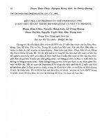
The realized sensing microgripper is shown in Fig. 5. The
device is 490 μm long, 350 μm wide, 30 μm thick, and with
a 40-μm gap between the two jaws. The piezoresistive forcesensing cantilever is 390 μm long and 10 μm wide with four
piezoresistors on the surface [see Fig. 5(b)]. Other parameters
related to the geometry can be found in Table I. The fabrication
process (see Fig. 6) is based on the Delft Institute of Microsystems and Nanoelectronics (DIMES) bipolar process [26], [31]
and the silicon-polymer actuator process [7], [32].
SOI wafers with 527-μm-thick silicon (p-type, 100 orientation), 400-nm-thick silicon buried dioxide layer, 30-μmthick single-crystal silicon layer (p-type, 100 orientation),
and 1-μm-thick n-type epitaxial layer, with a resistivity of
0.5 Ω · cm, are used. An additional 500-nm-thick p-type
epitaxial layer with a resistivity of 3.75 × 10⁻² Ω · cm is
grown to form the piezoresistors. By using epitaxial growth,
a uniformly doped layer with an accurate thickness within
2%–3% of nominal value can be obtained, resulting in resistors
of well-defined sizes. The piezoresistors are defined using
reactive ion etching (RIE) of silicon as shown in Fig. 6(b).
A 300-nm-thick low-pressure chemical-vapor-deposited silicon nitride layer is deposited as an electrical insulation layer
on the front side. On the back side, it serves as the masking
layer during etching in KOH solution. Then, on the wafer
front side, contact windows are opened, and a 600-nm-thick
aluminum layer is deposited. The piezoresistor connections and
electrothermal heaters are defined by using RIE [see Fig. 6(c)].
1550
JOURNAL OF MICROELECTROMECHANICAL SYSTEMS, VOL. 17, NO. 6, DECEMBER 2008
Fig. 5. SEM pictures of (a) sensing microgripper and close-ups of (b) piezoresistors, (c) jaws, and (d) section of the thermal actuator.
IV. M EASUREMENT S ETUPS
Fig. 6. Schematic view of the sensing microgripper fabrication process.
The top silicon layer is subsequently etched by deep RIE
to define the silicon frame until the buried oxide layer is
reached [Fig. 6(d)]. Negative photosensitive SU8 2002 polymer
is applied and patterned [see Fig. 6(e)]. A special prebake and
postbake procedure is followed to ensure the void-free filling
of the high aspect ratio structures. More details can be found in
[7]. Finally, the bulk silicon is etched from the back side in a
33-wt% KOH solution at 85 ◦ C until the buried silicon dioxide
layer is reached. The front side of the wafer is protected during
the etching in KOH by a vacuum holder. The last step is the
release of the structure by dry etching the buried silicon dioxide
layer from the back side [see Fig. 6(f)].
For the electrical characterization of the microgripper, dc
voltages are applied by using an HP4155A semiconductor
parameter analyzer (Agilent Technologies, Inc.). The voltage is
ramped from 0 to 4.5 V. The displacement is monitored by the
charge-coupled device camera on the top of the probe station.
The static displacement of the microgripper at any actuating
voltage is then obtained by enlarging the picture and comparing
it with the initial picture. External mechanical vibrations cause
a blur on the static picture which determines the accuracy
of the measurement. This inaccuracy is about ±1.5 μm. At
the same time, a bias voltage VCC with an amplitude of
1 V is applied to the Wheatstone bridge. The Wheatstone
bridge output is also monitored by the semiconductor parameter
analyzer.
The thermal behavior of the microgripper is investigated
by using a Cascade probe station with a heated wafer chuck
(Cascade Microtech, Inc.). The investigated temperature range
is from 20 ◦ C to 200 ◦ C (the highest temperature of this
measurement system) with 10 ◦ C stages and an accuracy of
±0.1 ◦ C. In order to get a stable temperature on the device, the
measurement is performed 5 min after the chuck temperature
has reached the setting point to allow sufficient stabilization.
This externally supplied thermal energy causes expansion in the
constrained polymer layer and the resulting actuation.
A DSP lock-in amplifier SR850 (Stanford Research
Systems, Inc.) is used to characterize the frequency behavior
of this sensing microgripper. A sine signal with amplitude of
VPP = 4 V, offset of 2 V, and frequency in the range from 0.1
to 500 Hz is applied to the actuator. The corresponding output
signal of the Wheatstone bridge is recorded.
CHU DUC et al.: MICROGRIPPER WITH LARGE JAW DISPLACEMENT AND INTEGRATED FORCE SENSORS
1551
Fig. 7. Device operation: (a) Initial position of the sensing microgripper jaws,
(b) when 4.5 V is applied to both arms.
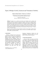
Fig. 9. Sensing microgripper jaw displacement versus power consumption.
Fig. 8. Simulated and measured sensing microgripper jaw displacement versus applied voltage. The maximum measured displacement is 32 µm at 4.5 V.
V. M EASUREMENT R ESULTS
A. Electrothermal Actuator Characteristics
Fig. 7 shows the images of several typical positions of
the microgripper jaws. In Fig. 7(a), the initial position is where
the gap between the two jaws which is 40 μm can be seen. The
distance between the two jaws is close to 8 μm when applying
a voltage of 4.5 V to both arms [see Fig. 7(b)].
Fig. 8 shows the displacement response of the microgripper
jaws in air when a dc voltage is applied to the electrothermal
actuator. This measured movement is the total change between
the two microgripper jaw positions when both arms are activated. The measured results are within 7.5% of the simulated
value for all data points. A maximum movement of 32 μm
is measured at an applied voltage of 4.5 V. Therefore, this
presented microgripper is capable of manipulating a microobject with a diameter from 8 to 40 μm.
The power consumption is calculated by the applied voltage
and the corresponding current on the electrothermal microactuators. Fig. 9 shows the measured with linear fitted and simulated
values of the jaw displacement versus power consumption. On
average, the device needs around 5 mW for a 1-μm displacement of the microgripper jaws.
Fig. 10. Sensing microgripper jaw displacement versus average working
temperature.
The average increasing temperature in the electrothermal
actuator ΔTave can be estimated by monitoring the change of
the resistance of the aluminum heater. It is given by
ΔTave =
Ract (ΔTave ) − Ract (ΔT0 ) 1
Ract (T0 )
αAl
(7)
where αAl is the TCR of aluminum film (see Table II), Ract (T0 )
is the resistance of the electrothermal actuator (205 Ω at room
temperature of −20◦ C), and Ract (ΔTres ) is the resistance of
the actuator when the average temperature on the actuator is
changed by ΔTave degrees. The maximum resistance change is
72% at the applied voltage of 4.5 V, resulting in a maximum
average temperature change of 176 ◦ C. Fig. 10 shows the
jaw displacement versus the average working temperature. The
experimental values come within 7% of the simulated ones.
The results of the thermal characterization are also shown
in Fig. 10. The values obtained with the external heat mode
come within 7% and 5% of the electrical and simulated ones,
respectively. It indicates that the aluminum depositing process
behaves as expected, and the average working temperature of
1552
JOURNAL OF MICROELECTROMECHANICAL SYSTEMS, VOL. 17, NO. 6, DECEMBER 2008
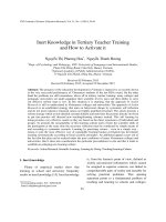
Fig. 11 also shows the output voltage of the piezoresistive
force-sensing cantilever when the microgripper grips a 23-μmdiameter object with the inset clamped object image. The sensing microgripper jaws close gradually until it grips the object.
The contact force between the microgripper jaws and the
clamped object can be estimated by the jaw displacement in
Fig. 11, considering the simulated gripper arm stiffness of
1.8 kN/m (see Table III). The contact force between gripper
jaws and object at the applied voltage V is then calculated as
FContact = Kl ∗ (d (V ) − d(V ))
Fig. 11. Output voltage of the force-sensing cantilever versus the applied
voltage on the electrothermal microactuator. The inset shows the microgripper
jaws with the clamped object.
the actuator can be well estimated from the resistance change
of the aluminum heater.
However, the physical properties of a polymer material such
as the volume coefficient of expansion, Young’s modulus, and
so on are greatly changed in pseudosecond order at the glass
transition temperature Tg where the material properties change
from the glassy region to the rubbery plateau region [33]. The
glass transition temperature of a polymer varies widely with
parameters such as the fabrication process and the microscopic
structure [17], [33], [34]. The Tg of SU8 is nearly the baking
temperature when it is below 220 ◦ C for a baking time of 20 min
[17]. However, the Tg can increase gradually up to the steadystate temperature of 118 ◦ C when the material is baked for a
longer time (60 min) at a constant temperature of 95 ◦ C.
The effect of the glass transition temperature is apparent
in the measurements of Fig. 10, where two different working
ranges can be distinguished. The data points lay along straight
fitting lines, which intersect each other just above 120 ◦ C.
This is fairly close to the steady-state SU8 glass transition
temperature of 118 ◦ C reported in [17]. It indicates that the
proposed postbake process of this device is sufficient in this
context. Furthermore, it explains the nonlinear characteristic of
the displacements due to the power consumption and also the
working temperature (see Figs. 9 and 10).
B. Force-Sensing Cantilever Beam Characteristics
Fig. 11 shows the measured output signal of the Wheatstone
bridge versus the voltage applied on the electrothermal microactuator. The zero-stress resistance value of the piezoresistors at room temperature is 39 kΩ. The bias voltage is 1 V dc.
The maximum output voltage of the sensor bridge is 49 mV
when the voltage applied to the actuator is 4.5 V. The relation
between the output voltage and the sensing microgripper jaw
displacement is also shown in Fig. 11. The sensitivity of the
sensing microgripper derived from this curve is 1.5 kV/m.
This curve is linear within 2%. The experimental results come
within 10% of the calculated ones obtained from (4), indicating
that the epitaxial growth, etching process, and resistor contacts
behave as expected.
(8)
where Kl is the lateral stiffness of the sensing microgripper
arm, d (V ) is the displacement of microgripper jaws at applied
voltage V without the clamped object in between the two
jaws (dashed line in Fig. 11), and d(V ) is the displacement of
microgripper jaws at applied voltage V with the clamped object
in between the two jaws (solid line in Fig. 11).
Fig. 12 shows the calculated contact force of this proposed
microgripper. The contact force is zero until the two gripper
jaws reach the object at an applied voltage of about 3.75 V. The
contact force then increases up to 135 mN at the applied voltage
of 4.5 V. Combining the measured results in Fig. 11 and the
calculated force, the sensitivity of this built-in force sensing is
estimated to be 1.7 V/N.
This sensing microgripper is capable of detecting the diameter of the clamped object and also the contact force between
the microgripper jaws and the object. This function is highly
desirable for the closed-loop system needed in microassembly, microrobotics, minimally invasive surgery, and living cell
surgery.
C. Response Frequency of the Sensing Microgripper
Fig. 13 shows the measured voltage gain and phase shift as
a function of frequency of this sensing microgripper using the
lock-in amplifier. The large-signal cutoff frequency of this sensing microgripper is measured as 29 Hz. The transient response
of the full range displacement of this sensing microgripper is
also characterized. The rise and settling times are measured to
be 13 and 18 ms, respectively.
Combining (6) and the output signal from Fig. 11 with the
frequency bandwidth of the range 0.1–29 Hz, the MDD and
the corresponding MDF of the sensing cantilever beam can be
estimated to be about 1 nm and 770 nN, respectively.
D. Reliability
The main failure mechanism observed during the test of
the microgripper is the appearance of cracks in the aluminum
heater and the silicon comb structure when the applied voltage
is increased to about 5 V and the working temperature of
the actuator is too high. There is no indication of the loss of
adhesion between the SU8 and the silicon plates even at these
temperatures. To investigate the lifetime of the microgripper, it
is repeatedly actuated in air with a 4-V amplitude (90% of its
maximum displacement) and with a time period of 6 s/sweep
for 24 h (14 400 cycles). The same reliability testing process is
CHU DUC et al.: MICROGRIPPER WITH LARGE JAW DISPLACEMENT AND INTEGRATED FORCE SENSORS
1553
TABLE III
PERFORMANCE OF THE SENSING MICROGRIPPER
Fig. 12. Contact force between microgripper jaws and the objects versus the
applied voltage.
Fig. 14. Microgripper is bonded on the modified dual in-line package. In this
way, both mechanical manipulation and electrical connection of the sensing
microgripper are possible.
modified socket chip (see Fig. 14). Then, the chip is mounted on
an xyz micromanipulator that allows moving the microgripper
in three dimensions.
As testing objects, ∼30-μm-diameter glass balls placed on a
silicon wafer surface are used. The glass balls are rearranged to
form the letter “L” as shown in Fig. 15. The microgripper tip is
moved to approach the ball [see Fig. 15(a)]. The microgripper
closes to grasp the object. The chip is then moved to the target
position using the xyz manipulator [see Fig. 15(b) and (c)]. The
microgripper finally opens to release the ball [see Fig. 15(d)].
When releasing the glass ball, we sometimes observe stiction
between the microgripper jaw and the object. However, we can
get rid of this adhesion force by applying a small force between
the glass ball and the silicon wafer surface before releasing
the object.
Fig. 13. Bode diagram of the sensing microgripper. The sweep input voltage
is applied to electrothermal actuator, and the output of the piezoresistive
Wheatstone bridge is monitored. The cutoff frequency is 29 Hz.
repeated after one week and then one month. No degradation in
performance is noticed.
E. Object Manipulation
The microparticle manipulating ability of this microgripper
developed is investigated. The microgripper is bonded on the
VI. C ONCLUSION
A novel design of a sensing microgripper based on
silicon-polymer electrothermal actuators and piezoresistive
force-sensing cantilever beams is presented. The sensing
microgripper is 490 μm long, 350 μm wide, and 30 μm thick. A
microgripper jaw displacement up to 32 μm at an applied voltage of 4.5 V is measured. The microgripper can be used to grasp
an object with a diameter of 8–40 μm. The maximum average
1554
JOURNAL OF MICROELECTROMECHANICAL SYSTEMS, VOL. 17, NO. 6, DECEMBER 2008
R EFERENCES
Fig. 15. Manipulating micro-glass balls to form letter L: (a) Initial position.
(b) Microgripper closes to grasp the ball. (c) Microgripper is moved to the right
position. (d) Microgripper opens to release the ball.
working temperature change is 176 ◦ C at 4.5 V. The output voltage of the piezoresistive sensing cantilever is up to 49 mV when
the jaw displacement is 32 μm. The force sensitivity is measured to be up to 1.7 nN/m, and the corresponding displacement
sensitivity is 1.5 kV/m. The bandwidth frequency of this presented sensing microgripper is measured as 29 Hz. The MDD
and MDF are estimated to be 1 nm and 770 nN, respectively.
The fabrication process is based on conventional bulk micromachining and polymer filling, and it is CMOS compatible. The
characteristics of this sensing microgripper will make the manipulation of small objects more efficient, more accurate, and
less tiring than with currently available grippers due to its large
jaw displacement and sensing sensitivity. The presented sensing microgripper could be used in automatic systems for microassembly and in microrobotics. In addition, the microgripper
could be of use in living cell handling or in minimally invasive
surgery, provided the working temperature is lowered and the
electronics are properly isolated from the liquid environment.
ACKNOWLEDGMENT
The authors would like to thank the DIMES-IC Processing
group for the technical support, P. J. F. Swart of the Electronic
Components, Technology and Materials group for the help,
G. de Graaff of the Electronics Instrumentation Laboratory for
the help with the electronic and mechanical measurements, and
J. Wei, M. Saadaoui, and H. W. van Zeijl of the Electronic Components, Technology and Materials group and S. L. Paalvast and
W. J. Venstra of the Precision and Microsystems Engineering
Department for their suggestions and discussions.
[1] M. C. Carrozza, P. Dario, and L. P. S. Jay, “Micromechanics in surgery,”
Trans. Inst. Meas. Control, vol. 25, no. 4, pp. 309–327, 2003.
[2] A. Menciassi, A. Eisinberg, M. C. Carrozza, and P. Dario, “Force sensing microinstrument for measuring tissue properties and pulse in microsurgery,” IEEE/ASME Trans. Mechatronics, vol. 8, no. 1, pp. 10–17,
Mar. 2003.
[3] D. H. Kim, M. G. Lee, B. Kim, and Y. Sun, “A superelastic alloy microgripper with embedded electromagnetic actuators and piezoelectric
force sensors: A numerical and experimental study,” Smart Mater. Struct.,
vol. 14, no. 6, pp. 1265–1272, Dec. 2005.
[4] G. Greitmann and R. A. Buser, “Tactile microgripper for automated handling of microparts,” Sens. Actuators A, Phys., vol. 53, no. 1, pp. 410–415,
May 1996.
[5] K. Molhave and O. Hansen, “Electro-thermally actuated microgrippers
with integrated force-feedback,” J. Micromech. Microeng., vol. 15, no. 6,
pp. 1256–1270, Jun. 2005.
[6] F. Beyeler, A. Neild, S. Oberti, D. J. Bell, Y. Sun, J. Dual, and B. J. Nelson,
“Monolithically fabricated microgripper with integrated force sensor for
manipulating microobjects and biological cells aligned in an ultrasonic
field,” J. Microelectromech. Syst., vol. 16, no. 1, pp. 7–15, Feb. 2007.
[7] T. Chu Duc, G. K. Lau, and P. M. Sarro, “Polymeric thermal microactuator
with embedded silicon skeleton: Part II—Fabrication, characterization,
and application for 2-DOF microgripper,” J. Microelectromech. Syst.,
vol. 17, no. 4, pp. 823–831, Aug. 2008.
[8] T. Chu Duc, J. F. Creemer, and P. M. Sarro, “Piezoresistive cantilever
beam for force sensing in two dimensions,” IEEE Sensors J., vol. 7, no. 1,
pp. 96–104, Jan. 2007.
[9] T. Chu Duc, G. K. Lau, J. F. Creemer, and P. M. Sarro, “Electrothermal microgripper with large jaw displacement and integrated force
sensors,” in Proc. 21st IEEE Conf. MEMS, Tucson, AZ, Jan. 13–17, 2008,
pp. 519–522.
[10] T. Chu Duc, G. K. Lau, J. Wei, and P. M. Sarro, “2D electro-thermal
microgrippers with large clamping and rotation motion at low driving
voltage,” in Proc. 20th IEEE Conf. MEMS, Kobe, Japan, Jan. 21–25, 2007,
pp. 687–690.
[11] T. Chu Duc, G. K. Lau, and P. M. Sarro, “Polymer constraint effect for
electrothermal bimorph microactuators,” Appl. Phys. Lett., vol. 91, no. 10,
p. 101 902-3, Sep. 2007.
[12] G. K. Lau, J. F. L. Goosen, F. van Keulen, T. Chu Duc, and
P. M. Sarro, “Polymeric thermal microactuator with embedded silicon skeleton: Part I—Design and analysis,” J. Microelectromech. Syst.,
vol. 17, no. 4, pp. 809–822, Aug. 2008.
[13] NANO SU-8 2000 Negative Tone Photoresist Formulations 2002-2025,
MicroChem Corporation, Newton, MA. [Online]. Available: www.
microchem.com
[14] H. M. Chuang, S. F. Tsai, K. B. Thei, and W. C. Liu, “Anomalous
temperature-dependent characteristics of silicon diffused resistors,”
Electron. Lett., vol. 39, no. 13, pp. 1015–1016, Jun. 2003.
[15] J. J. Wortman and R. A. Evans, “Young’s modulus, shear modulus, and
Poisson’s ratio in silicon and germanium,” J. Appl. Phys., vol. 36, no. 1,
pp. 153–156, Jan. 1965.
[16] J. F. Creemer and P. J. French, “The saturation current of silicon bipolar
transistors at moderate stress levels and its relation to the energy-band
structure,” J. Appl. Phys., vol. 96, no. 8, pp. 4530–4538, Oct. 2004.
[17] R. Feng and R. J. Farris, “Influence of processing conditions on the
thermal and mechanical properties of SU8 negative photoresist coatings,”
J. Micromech. Microeng., vol. 13, no. 1, pp. 80–88, Jan. 2003.
[18] R. Feng and R. J. Farris, “The characterization of thermal and elastic
constants for an epoxy photoresist SU8 coating,” J. Mater. Sci., vol. 37,
no. 22, pp. 4793–4799, Nov. 2002.
[19] L. J. Gukrin, M. Bossel, M. Demierre, S. Calmes, and P. Renaud, “Simple
and low cost fabrication of embedded microchannels by using a new thickfilm photoelastic,” in Proc. Transducers, 1997, pp. 1419–1422.
[20] J. F. Shackelford and W. Alexander, CRC Material Science and Engineering Handbook, 3rd ed. Boca Raton, FL: CRC Press, 2001.
[21] M. Chinmulgund, R. B. Inturi, and J. A. Barnard, “Effect of Ar gas
pressure on growth, structure, and mechanical properties of sputtered
Ti, Al, TiAl, and Ti3 Al films,” Thin Solid Films, vol. 270, no. 1/2,
pp. 260–263, Dec. 1995.
[22] V. E. Zinovev, Handbook of Thermophysical Properties of Metals at High
Temperatures. Commack, NY: Nova, 1996.
[23] N. D. Mankame and G. K. Ananthasuresh, “Comprehensive thermal
modelling and characterization of an electro-thermal-compliant microactuator,” J. Micromech. Microeng., vol. 11, no. 5, pp. 452–462,
Sep. 2001.
CHU DUC et al.: MICROGRIPPER WITH LARGE JAW DISPLACEMENT AND INTEGRATED FORCE SENSORS
[24] Q. A. Huang and N. K. S. Lee, “Analysis and design of polysilicon thermal
flexure actuator,” J. Micromech. Microeng., vol. 9, no. 1, pp. 64–70,
Mar. 1999.
[25] N. Chronis and L. P. Lee, “Electrothermally activated SU-8 microgripper for single cell manipulation in solution,” J. Microelectromech. Syst.,
vol. 14, no. 4, pp. 857–863, Aug. 2005.
[26] T. Chu Duc, J. F. Creemer, and P. M. Sarro, “Lateral nano-Newton
force-sensing piezoresistive cantilever for microparticle handling,”
J. Micromech. Microeng., vol. 16, no. 6, pp. S102–S106, Jun. 2006.
[27] J. M. Gere, Mechanics of Materials, 6th ed. Belmont, CA: Brooks/Cole,
2004.
[28] R. C. Jaeger, J. C. Suhling, M. T. Carey, and R. W. Johnson,
“Off-axis sensor rosettes for measurement of the piezoresistive coefficients of silicon,” IEEE Trans. Compon., Hybrids, Manuf., vol. 16, no. 8,
pp. 925–931, Dec. 1993.
[29] J. A. Harley and T. W. Kenny, “1/F noise considerations for the design
and process optimization of piezoresistive cantilevers,” J. Microelectromech. Syst., vol. 9, no. 2, pp. 226–235, Jun. 2000.
[30] X. Yu, J. Thaysen, O. Hansen, and A. Boisen, “Optimization of sensitivity
and noise in piezoresistive cantilever,” J. Appl. Phys., vol. 92, no. 10,
pp. 6296–6301, Nov. 2002.
[31] L. K. Nanver, E. J. G. Goudena, and H. W. van Zeijl, “Optimization
of fully-implanted NPNs for high-frequency operation,” IEEE Trans.
Electron Devices, vol. 43, no. 6, pp. 1038–1040, Jun. 1996.
[32] T. Chu Duc, G. K. Lau, J. Wei, and P. M. Sarro, “Integrated siliconpolymer laterally stacked bender for sensing microgrippers,” in Proc. 5th
IEEE Conf. Sensors, 2006, pp. 662–665.
[33] L. H. Sperling, Introduction to Physical Polymer Science. Hoboken, NJ:
Wiley, 2006.
[34] J. H. van Zanten, W. E. Wallace, and W. Wu, “Effect of strongly favorable substrate interactions on the thermal properties of ultrathin polymer
films,” Phys. Rev. E, Stat. Phys. Plasmas Fluids Relat. Interdiscip. Top.,
vol. 53, no. 3, pp. R2053–R2056, Mar. 1996.
Trinh Chu Duc received the B.S. degree in
physics from Hanoi University of Science, Hanoi,
Vietnam, in 1998, the M.Sc. degree in electrical
engineering from Vietnam National University,
Hanoi, in 2002, and the Ph.D. degree from Delft
University of Technology, Delft, The Netherlands,
in 2007. His doctoral research concerned
piezoresistive sensors, polymeric actuators, sensing
microgrippers for microparticle handling, and
microsystems technology.
He is currently an Assistant Professor with the
Faculty of Electronics and Telecommunication, College of Technology,
Vietnam National University.
Gih-Keong Lau received the B.Eng. (with first-class
honors) and M.Eng. (by research) degrees in mechanical engineering from Nanyang Technological
University (NTU), Singapore, in 1998 and 2001,
respectively, and the Ph.D. degree from Delft University of Technology, Delft, The Netherlands, in 2007,
where his research topics were polymer microactuators and microfabrication.
From 2001 to 2003, he was a Research Associate
with the Centre for Mechanics of Microsystems,
NTU, where he worked on the topology optimization
of compliant mechanisms and piezoelectric actuators for hard disk drives and,
since 2008, has been an Assistant Professor with the School of Mechanical and
Aerospace Engineering. His current research interests are electroactive polymer
actuators and their microfabrication.
1555
J. Fredrik Creemer (S’97–A’01–M’03) received
the M.Sc. degree in electrical engineering from Delft
University of Technology, Delft, The Netherlands,
in 1995, the Diplôme d’Études Approfondis in electronics from the Université Paris-Sud, Orsay, France,
in 1996, and the Ph.D. degree (cum laude) from
Delft University of Technology, in 2002. His doctoral
research explored the effect of mechanical stress on
bipolar transistor characteristics.
He was an Analog Chip Designer, with SystematIC Design from 2002 to 2003. In 2003, he
was with the Kavli Institute of Nanoscience, as a Postdoctoral Researcher.
In 2006, he was an Assistant Professor with the Laboratory for Electronic
Components, Technology and Materials, Delft Institute of Microsystems and
Nanoelectronics, Delft University of Technology. His research interests are microelectromechanical system microreactors, transmission electron microscopy,
and microsystems technology.
Dr. Creemer was the recipient of the Else Kooi Award 2002 for the research
described in his dissertation and, in 2006, a Veni Grant.
Pasqualina M. Sarro (M’84–SM’7–F’07) received
the Laurea degree (cum laude) in solid-states physics
from the University of Naples, Naples, Italy, in
1980, and the Ph.D. degree in electrical engineering from Delft University of Technology, Delft,
The Netherlands, in 1987, where her thesis dealt
with infrared sensors based on integrated silicon
thermopiles.
From 1981 to 1983, she was a Postdoctoral Fellow with the Photovoltaic Research Group, Division
of Engineering, Brown University, Providence, RI.
She then joined the Delft Institute of Microsystems and Nanoelectronics, Delft
University of Technology, where she is responsible for research on integrated
silicon sensors and microelectromechanical systems (MEMS) technology. In
December 2001, she became the A. van Leeuwenhoek Professor, and, since
2004, has been the Head of the Electronic Components, Materials and Technology Laboratory. She has authored or coauthored more than 350 journal and
conference papers.
Dr. Sarro was the recipient of the EUROSENSORS Fellow Award in 2004
for her contribution to the field of sensor technology. In April 2006, she
became a member of the Dutch Royal Academy of Science, and in November
2006, she was elected an IEEE Fellow for her contributions to micromachined
sensors, actuators, and microsystems. She is a member of the technical program
committees for several international conferences (IEEE MEMS, IEEE Sensors,
EUROSENSORS, and Transducers), the Technical Program Cochair for the
First IEEE Sensors 2002 Conference, and the Technical Program Chair for
the Second and Third IEEE Sensors Conference (2003 and 2004). She is the
General Cochair of IEEE MEMS 2009. She is also a member of the AdCom of
the IEEE Sensors Council.