DSpace at VNU: Fast and slow light enhancement using cascaded microring resonators with the Sagnac reflector
Bạn đang xem bản rút gọn của tài liệu. Xem và tải ngay bản đầy đủ của tài liệu tại đây (839.66 KB, 12 trang )
Accepted Manuscript
Title: FAST AND SLOW LIGHT ENHANCEMENT USING
CASCADED MICRORING RESONATORS WITH THE
SAGNAC REFLECTOR
Author: Duy-Tien Le Manh-Cuong Nguyen Trung-Thanh Le
PII:
DOI:
Reference:
S0030-4026(16)31356-0
/>IJLEO 58453
To appear in:
Received date:
Revised date:
Accepted date:
3-9-2015
31-10-2016
7-11-2016
Please cite this article as: Duy-Tien Le, Manh-Cuong Nguyen, Trung-Thanh Le,
FAST AND SLOW LIGHT ENHANCEMENT USING CASCADED MICRORING
RESONATORS WITH THE SAGNAC REFLECTOR, Optik - International Journal
for Light and Electron Optics />This is a PDF file of an unedited manuscript that has been accepted for publication.
As a service to our customers we are providing this early version of the manuscript.
The manuscript will undergo copyediting, typesetting, and review of the resulting proof
before it is published in its final form. Please note that during the production process
errors may be discovered which could affect the content, and all legal disclaimers that
apply to the journal pertain.
FAST AND SLOW LIGHT ENHANCEMENT USING CASCADED MICRORING
RESONATORS WITH THE SAGNAC REFLECTOR
1
Duy-Tien Le, 2Manh-Cuong Nguyen, and 3*Trung-Thanh Le
1
Posts and Telecommunications Institute of Technology (PTIT) and Finance-Banking University, Hanoi,
Vietnam
2
Le Quy Don Technical University, Hanoi, Vietnam
3
International School (IS-VNU), Vietnam National University (VNU), Hanoi, Vietnam
3
Email:
Phone: +84-985 848 193
Abstract
A cascaded microring resonator based on silicon waveguides with an MMI (Multimode Interference)
based Sagnac reflector is proposed in this study. By controlling the coupling coefficients with the used of the
MMI based Sagnac reflector, the double of both pulse delay and advancement for the slow and fast light can
be achieved. The new structure can produce the fast and slow light phenomenon on one chip with a double of
the time delay and pulse advancement. By using the Sagnac reflector, the device is very compact. Transfer
matrix method and FDTD (Finite Difference Time Domain) simulation are used to obtain the characteristics
of the device. The transmission, phase, group delay and pulse propagation are analyzed in detail. Our FDTD
simulations show a good agreement with the analytical theory.
Keywords: Microring resonator, fast light, slow light, silicon waveguides, FDTD, transfer matrix
method, multimode interference (MMI), microresonators
1. Introduction
In recent years, optical microring resonators have been of great interest for applications in optical
communications such as optical delay lines, optical switches, modulators, filters, dispersion compensators
etc. [1, 2]. Micro-ring resonator structures consists of a number of single micro-ring resonators cascaded in
series or in parallel can be used for higher order filters with extended free spectral ratios [3] or switching [4],
modulating applications [5], fast and slow light [6].
Analysis of the group delay and transmission characteristics of cascaded microring resonators used for
optical filters and dispersion compensators have been studied [7-9]. However, these structures have positive
group delay and mainly designed for pulse delay applications. Slow and fast light generation are emerging
as a very attractive research topic. Various techniques have been developed to realize fast light and slow light
in atomic vapors and solid-state materials [10]. One application among these techniques is to control the
group velocity v g of light pulses to make them propagate either very slow ( v g < c) or very fast ( v g > c or
v g is negative), where c is the velocity of light.
In this study, we propose a new cascaded microring structure based on silicon waveguides with a Sagnac
loop reflector. The Sagnac loop reflector has been applied to many application structures such as filtering
and fast light structures [11, 12]. By controlling the coupling coefficients of the coupler used in microring
resonators in the proposed structure, negative and positive group delay can be obtained. This means that the
light velocity can be controlled and therefore the fast and slow light can be induced by the structure [13-15].
Here, we use a Sagnac loop reflector based on an 1x2 MMI (Multimode Interference coupler) at the end of
the structure to enhance the fast and slow light. The use of an MMI based reflector for the reflection to
double the pulse delay and pulse advancement. It is shown that the group delay, time delay and advancement
are doubled compared to the case without using the MMI Sagnac loop reflector. We use silicon microring
resonators because of high quality of fabrication by using CMOS compatible process and device
compactness with a high index contrast system.
2. Design
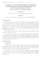
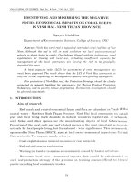
The structure consisting of N-single microring resonators cascaded in series with a Sagnac loop reflector
is proposed in Figure 1(a).
1
(a)
R1
E1
E2
1
(b)
Figure 1: (a) Cascaded microring resonators with Sagnac loop reflector amd (b) Single microring
resonator
2.1. Single microring resonator
For a single microring resonator as shown in Figure 1(b), the output field can be related to the input field
by the expression [16]
(1)
| | are the transmission
Where
are the field amplitude at the input and output;
and
√
and coupling coefficients of the coupler;
is the loss factor in the ring waveguide and
is
the accumulated phase shift over the ring waveguide.
is the effective refractive index of the waveguide,
is the wavelength and
is the circumference of the ring waveguide.
The effective phase shift of the microring resonator can be defined by
{
}
The normalized group delay is given by n
{
}
(2)
dsingle
. The absolute group delay is d T n , where T
d
is the unit delay of the signal propagating over the microring waveguide. The resonance is occurred at the
phase 1 2m , where m is an integer. At resonance, 1 1 the ring resonator and waveguide is undercoupled and leading to pulse advancement or fast light; when 1 1 , they are over-coupled and leading to
pulse delay or slow light; the critical coupling occurs when 1 1 .
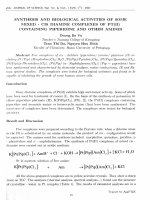
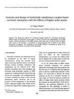
The transmission, phase and group delay of the single microring resonator at the transmission coefficients
1 0.9975, 0.9966 and 0.99 respectively are shown in Figure 2. The parameters are set as follows: the loss
factor of the waveguide 1 1dB / cm , the length of the microring waveguide LR1 300m . The
simulation shows that the positive and negative group delay can be achieved by adjusting the coupling
coefficient of the coupler. It is assumed that a silicon waveguide with a height of 220 nm and width of 400
nm and refractive index Neff 2.25 .
Figure 2: Transmission, phase and group delay characteristics of the single microring resonator
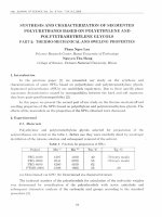
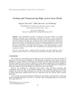
We now investigate the pulse propagation over the single ring resonator. It is assumed that the input pulse
is Gaussian and can be expressed as [17]
E(t ) exp((t / THW )2 )exp( j 2 ct / 0 )
(3)
Where 0 is the resonance wavelength of the single microring resonator, THW Tb / 2 is the bit half
width at 1/ e2 intensity and Tb is the bit period. From the simulations of Figure 2, the resonance wavelength
is 0 1.54817 m . The input and corresponding output pulses with the transmission coefficients
1 0.9975, 0.9966 and 0.99 are shown in Figure 3, where the input pulse width Tp 50 ps [18]. The
simulations show that pulse delay of 20ps can be obtained when 1 0.99 and when 1 0.9975 the pulse
advancement of 12ps is obtained.
2.2. Cascaded microring resonators
A side coupled integrated spaced sequence of resonators (SCISSOR) or cascaded microring resonator
without the Sagnac reflector has been firstly proposed by Heebner and Boyd [19]. It was shown that by using
SCISSOR structure, fast and slow light can be obtained. Here, we consider a SCISSOR as shown in Figure 1
with a Sagnac loop reflector. For simplicity, we assume that N ring resonators are identical. As a result, the
transfer function of the SCISSOR can be written by
H SCISSOR
Here
and
exp j
E
H1 H 2 ...H N ( 2 ) N
E1
1 exp j
is the loss factor in the ring waveguide and
3
N
(4)
.
Figure 3: Input and output pulses at the single microring resonator
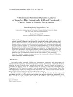
The transmission, phase and group delay of the cascaded microring resonator for N=1, 2, 3 are shown in
Figure 4 and 5. It is assumed that the transmission coefficient of the coupler is 1 0.99 and 0.9975 . The
simulation results show that slow and fast light are induced by adjusting the coupling coefficients. In
addition, the pulse delay and pulse advancement are increased by N times compared with the single
microring resonator.
2.3. Cascaded microring resonators with the Sagnac reflector
Figure 1 shows the cascaded microring resonator with the Sagnac reflector. In this study, we use an 1x2
MMI coupler in the Sagnac reflector. As a result, the transfer function of the proposed structure in Figure 1
can be expressed by
exp j
H (2 j s s s )
1 exp j
2N
(5)
| | are the transmission and coupling coefficients of the coupler of the Sagnac
Where
and
√
reflector and is the loss factor in the ring waveguide of the Sagnac reflector.
Figure 6(a) and (b) show the transmission, phase, group delay and output pulses propagating over the
structure with and without Sagnac reflector. It is assumed that the structure consisting of N identical
microring resonators (N=1 and 2) with the transmission coefficient of 1 0.99 . By using the Sagnac
reflector, we obtain the pulse delays of 43ps and 83ps for N=1 and 2 respectively, compared with 20ps and
40ps without using the Sagnac reflector.
When 1 0.9975 , the undercoupled condition occurs. Therefore, the fast light can be induced by using
the proposed structure. Figure 7(a) and (b) show the transmission characteristics and output pulses
propagating over the structure with and without Sagnac reflector. It is shown that pulse advancements of
25ps and 50ps are achieved when the Sagnac reflector is used (compared with 12ps and 24ps without the
Sagnac reflector).
(b) 1 0.9975
(a) 1 0.99
Figure 4: Transmission characteristics of the cascaded microring resonators (a) 1 0.99 and (b)
1 0.9975
Figure 5: Input and output pulses at the cascaded microring resonator structure
5
(a)
(b)
Figure 6: Transmission characteristics of the cascaded microring resonators (a) 1 0.99 and (b)
output pulses
(a)
(b)
Figure 7: Transmission characteristics of the cascaded microring resonators (a) 1 0.9975 and (b)
output pulses
7
By controlling the coupling coefficients of ring resonators, the fast and slow light can be achieved. The
pulse delay and advancement can be increased by N times if N identical ring resonators are used. Figure 8
shows the time delay and advancement of the pulse propagating through our prosed structure. We can see
that by using the Sagnac reflector, the pulse delay and advancement can be doubled compared with the
conventional SCISSOR structure.
Figure 8: Time delay and advancement with and without the Sagnac reflector
To verify the accuracy of the transfer matrix analysis, we compare the results obtained with the FDTD.
For our FDTD simulations, the radius of the microring resonator is to be R 5 m , the waveguide width is
Wa 400nm , the gap between the microring waveguide and the straight waveguide is chosen to be
2
2
g 160nm in order for the power transmission coupling ( ) to be 0.9 as shown in Figure 10(a).
Here we take into account the wavelength dispersion of the silicon waveguide using the expression
Neff ( ) 4.7020 1.6667 for 1.5 1.6 m (Figure 10(b)).
Figure 9: Directional coupler used for microring resonator
N eff ( ) 4.7020 1.6667
(a)
(b)
Figure 10: FDTD simulations (a) transmission coefficient at different gap and (b) wavelength dispersion
of the silicon waveguide with a width of 400nm (the inset shows the field at 1.55 m )
A Gaussian light pulse of 15fs pulse width is launched from the input to investigate the transmission
characteristics of the device. The grid size x y 0.02nm and z 0.05 are chosen in our simulations.
As shown in Figure 11(a) with a number of the microring resonator N=1 and Figure 12(a) with N=2, the
transmissions calculated by the FDTD are quite similar to the transmission calculated by the analytical
theory. Figure 11(b) and 12(b) show the FDTD field distributions at on and off-resonances.
Figure 11: FDTD simulation of the proposed structure with one ring resonator and Sagnac reflector.
9
Figure 12: FDTD simulation of the proposed structure with two ring resonators and Sagnac reflector
The simulation results for the deviation of the transmission coefficient 2 depending on the waveguide
width variation Wa are shown in Fig. 13. Due to the manufacturing tolerances, the variation in waveguide
width occurs and leading to a new waveguide width expressed by W Wa Wa . Adding to the change of
the transmission coefficient, the deviation of the waveguide width also leads to the change in effective index.
For a positive Wa , the effective index is increased. For any gap and radius, a positive Wa leads to a
decrease in the transmission coefficient. For Wa 10nm , the transmission coefficient is decreased by
0.044 for g=120nm and 0.037 for g=130nm at the same width Wa=450nm and radius R=10µm. While this
coefficient is decreased only by 0.012 if the ring radius R=5µm. As a result, the transmission coefficient of
the coupler is quite stable for a smaller ring radius and larger gap. For a width variation within ±20nm, a
deviation of the transmission coefficient of 13% can be obtained. For either e-beam or DUV lithography, size
deviations of up to ±20 nm from design are very easy [20].
(a)
(b)
Figure 13: Change of the transmission coefficient and the deviation from the calculated value at
Wa=450nm as the effect of the width variation
3. Conclusion
We have proposed a cascaded microring resonator with an MMI based Sagnac reflector. The
transmission, phase, group delay and pulse propagation characteristics are analyzed. The proposed structure
can induce the fast and slow light by controlling the coupling coefficients of the couplers. The time delay and
advancement can be doubled compared with the conventional SCISSOR structure without the Sagnac
reflector. The fabrication tolerance is high and suitable for CMOS fabrication technology.
ACKNOWLEDGEMENTS
This research is funded by Vietnam National Foundation for Science and Technology Development
(NAFOSTED) under grant number ―103.02-2013.72" and Vietnam National University, Hanoi (VNU) under
project number QG.15.30.
REFERENCE
[1]
J. Heebner, R. Grover, and T. Ibrahim, Optical Microresonators: Theory, Fabrication, and
Applications: Springer, 2008.
[2]
Ioannis Chremmos, Otto Schwelb, and Nikolaos Uzunoglu (Editors), Photonic Microresonator
Research and Applications: Springer, 2010.
[3]
Jianyi Yang, Qingjun Zhou, Feng Zhao et al., "Characteristics of optical bandpass filters employing
series-cascaded double-ring resonators," Optics Communications, vol. 228, pp. 91-98, December
2003.
[4]
Sang-Yeon Cho and Richard Soref, "Interferometric microring-resonant 2×2 optical switches,"
Optics Express, vol. 16, pp. 13304-13314, 2008.
[5]
Yingtao Hu, Xi Xiao, Hao Xu et al., "High-speed silicon modulator based on cascaded microring
resonators," Optics Express, vol. 20, pp. 15079-15085, 2012.
[6]
Tao Wang, Fangfei Liu, Jing Wang et al., "Pulse Delay and Advancement in SOI Microring
Resonators With Mutual Mode Coupling," Journal of Lightwave Technology, vol. 27, p. 4734,
2009.
[7]
Hao Shen, Jian-Ping Chen, Xin-Wan Li et al., "Group delay and dispersion analysis of compound
high order microring resonator all-pass filter," Optics Communications, vol. 262, pp. 200–205,
2006.
[8]
Chinda Chaichuay, Preecha P. Yupapin, and Prajak Saeung, "Multi-stage ring resonator all-pass
filters for dispersion compensation," Optica Applicata, vol. XXXIX, pp. 277-286, 2009.
[9]
Jingya Xie, Linjie Zhou, Zhi Zou et al., "Continuously tunable reflective-type optical delay lines
using microring resonators," Optics Express, vol. 22, pp. 817-823, 2014.
[10]
Robert W. Boyd and Daniel J. Gauthier, "Controlling the Velocity of Light Pulses," Science, vol.
326, pp. 1074-1077, 20 Nov 2009.
[11]
Salvador Vargas and Carmen Vázquez, "Synthesis of Optical Filters Using Sagnac Interferometer in
Ring Resonator," IEEE Photonics Technology Letters, vol. 19, p. 1877, 2007.
[12]
Tao Wang, Xiaohui Li, Fangfei Liu et al., "Enhanced fast light in microfiber ring resonator with a
Sagnac loop reflector," Optics Express, vol. 18, pp. 16156-16161, 2010.
[13]
M. Javed Akram, M. Miskeen Khan, and Farhan Saif, "Tunable fast and slow light in a hybrid
optomechanical system," Physical Review A, vol. 92, pp. 023846-, 2015.
[14]
Hiva Shahoei, Dan-Xia Xu, Jens H. Schmid et al., "Continuous Slow and Fast Light Generation
Using a Silicon-on-Insulator Microring Resonator Incorporating a Multimode Interference
Coupler," Journal of Lightwave Technology, vol. 32, 2014.
[15]
Ling Li, Wenjie Nie, and Aixi Chen, "Transparency and tunable slow and fast light in a nonlinear
optomechanical cavity," Scientific Reports, vol. 6, Article number: 35090, 2016.
[16]
A. Yariv, "Universal relations for coupling of optical power between microresonators and dielectric
waveguides," Electronics Letters, vol. 36, pp. 321–322, 2000.
[17]
Xin Liu, Mei Kong, and He Feng, "Transmission and dispersion of coupled double-ring resonators,"
Journal of the Optical Society of America B, vol. 29, pp. 68-74, 2012.
[18]
Myungjun Lee, Michael E Gehm, and Mark A Neifeld, "Systematic design study of all-optical delay
line based on Brillouin scattering enhanced cascade coupled ring resonators," Journal of Optics,
vol. 12, pp. 1-10, 2010.
[19]
John Heebner and Robert Boyd, "`Slow' and `fast' light in resonator-coupled waveguides," Journal
of Modern Optics, vol. 49, pp. 2629-2636, 2002.
[20]
Dan-Xia Xu, Jens H. Schmid, Graham T. Reed et al., "Silicon Photonic Integration Platform—Have
We Found the Sweet Spot?," IEEE Journal of Selected Topics in Quantum Electronics, vol. 20, pp.
8100217-, 2014.
11