DSpace at VNU: Size effect on the structural and magnetic properties of nanosized perovskite LaFeO 3 prepared by different methods
Bạn đang xem bản rút gọn của tài liệu. Xem và tải ngay bản đầy đủ của tài liệu tại đây (923.2 KB, 7 trang )
Hindawi Publishing Corporation
Advances in Materials Science and Engineering
Volume 2012, Article ID 380306, 6 pages
doi:10.1155/2012/380306
Research Article
Size Effect on the Structural and Magnetic Properties of
Nanosized Perovskite LaFeO3 Prepared by Different Methods
Nguyen Thi Thuy1 and Dang Le Minh2
1 Department
2 Faculty
of Physics, College of Education, Hue University, 34 Le Loi, Hue City, Vietnam
of Physics, Hanoi University of Sciences, VNU, 334 Nguyen Trai, Thanh Xuan, Hanoi City, Vietnam
Correspondence should be addressed to Nguyen Thi Thuy,
Received 24 April 2012; Accepted 19 June 2012
Academic Editor: David Cann
Copyright © 2012 N. T. Thuy and D. L. Minh. This is an open access article distributed under the Creative Commons Attribution
License, which permits unrestricted use, distribution, and reproduction in any medium, provided the original work is properly
cited.
Nanosized LaFeO3 material was prepared by 3 methods: high energy milling, citrate gel, and coprecipitation. The X-ray diffraction
(XRD), differential scanning calorimetry (DSC), and thermogravimetric analysis (TGA) show that the orthorhombic LaFeO3
phase was well formed at a low sintering temperature of 500◦ C in the citrate-gel and co-precipitation methods. Scanning electron
microscope (SEM) and transmission electron microscope (TEM) observations indicate that the particle size of the LaFeO3 powder
varies from 10 nm to 50 nm depending on the preparation method. The magnetic properties through magnetization versus
temperature M(T) and magnetization verses magnetic field M(H) characteristics show that the nano-LaFeO3 exhibits a weak
ferromagnetic behavior in the room temperature, and the M(H) curves are well fitted by Langevin functions.
1. Introduction
The perovskite-type oxides (general, formula ABO3, A,
and B are the metallic ions) have been attracting much
attention for more than two decades due to their potential commercial applications as catalysts for various reactions. Moreover, the modified perovskite compounds such
as La1−x Srx MnO3 , La1−x Prx MnO3 , La0.7 Sr0.3 Mn1−x Nix O3,
Ca1−x Ndx MnO3 , CaMn1−x Fex O3 , and so forth [1–7] have
received much attention because of their interesting physical
effects: colossal magnetoresistance (CMR), giant magnetocaloric effect (GMCE), and high thermoelectric performance (TEP) at high temperature. In recent years, many laboratories in the world have studied LaFeO3 as a thermoelectric material with high Seebeck coefficient and high power
factor and it can be used as catalyst for methane combustion,
the thin film gas sensors, and so forth. The LaFeO3 thin film
can be used as sensitive O2 gas sensors [8] and nano-sized
LaFeO3 powder can be used as catalyst for the autoreforming
of sulfur-containing fuels or for partial oxidation of methane
(POM) to (H2 /CO) [9–12]. For preparation of those nanomaterials, various technological methods are used such as coprecipitation, sol-gel, hydrothermal reactions, mechanical
alloying, pulsed wire discharge, shock wave, spray drying,
and so forth.
In the present study, the nano-sized LaFeO3 has been
prepared by 3 methods: high energy milling, citrate gel, and
co-precipitation. Beside determination of the particle size,
crystalline, and microstructures, the magnetic properties
were also investigated. The particle size of the samples
prepared by different methods influenced strongly on the
structural and magnetic properties of the material.
2. Experimental Procedure
The nano-LaFeO3 was prepared using sol-gel, co-precipitation, and high-energy milling methods. These methods were
performed as the following.
In the sol-gel method, the analytical grade La(NO)3 ·
6H2 O, Fe(NO3 )3 ·9H2 O, and citric acid (CA) C6 H8 O7 ·H2 O
were used as starting materials. The same mole equivalent
amounts of metal nitrates were weighed according to the
nominal composition LaFeO3 and then dissolved in distilled
water. The citric acid with the ratios (CA)/Σ(Metal ions) =
(1.2–1.5) was then proportionally added to the metal nitrates
solution. In the above ratio, (CA) and Σ(Metal ions)
2
Advances in Materials Science and Engineering
193.97◦ C
457.01◦ C
−5
120
100
80
−10
60
65.02%
−15
40
8.299%
−20
0
Exo up
200
Transmittance (%)
Heat flow (W/g)
0
140
( ) weight (%)
417.34◦ C
Citric acid
160
|
DSC-TGA
Sample: LaFeO3
240.55◦ C
5
896
20
3364
599
1420
1393
781
1729
1111
1213
400
600
800
Universal V3.88 TA instruments
Temperature (◦ C)
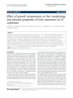
Figure 1: The DSC-TGA curves of the gel complex.
4000
3500
3000
2500
2000
1500
1000
500
Wavenumber (cm−1 )
3. Results and Discussion
Figure 1 shows the DSC and TGA curves for the sample
prepared by sol-gel method. It can be seen from Figure 1
that TGA curve exhibits a weight loss of about 65% corresponding to an exothermic peak in DSC curve at 240.55◦ C,
those are the removal of the water from crystallization and
decomposition process of the organic substances. Heating
at higher temperature led to a small weight loss (∼8.3%)
at 250◦ C and finishing at 500◦ C associated with a peak at
457.01◦ C in the DSC curve. The weight loss (∼65%) is due
to the chemical changes as shown in the following equation
[14]:
La(NO3 )3 · 6H2 O + Fe(NO3 ) · 9H2 O + C6 H8 O7 · H2 O
−→ LaFeO3 + 6CO2 + 2N2 + 2NO2 + 20H2 O
(1)
(a)
LaFeO3
1121
1402
2928
Transmittance (%)
are concentration of (CA) and sum of concentration of
metallic ions, respectively. The solution was concentrated by
evaporation at 60–70◦ C with continuous stirring and pH
controlled by NH3 solution. The nanocrystals of perovskite
LaFeO3 were obtained by decomposition of the dried gel
complex at selected temperatures: 300, 500, and 700◦ C in air.
In the co-precipitation method, La(NO3 )·6H2 O,
Fe(NO3 )3 ·4H2 O were raw materials. NH3 solution was
added to the metal nitrates solution. The La(OH)3 and
Fe(OH)3 were co-precipitated as hydroxide gel [13] at
80◦ C under continuous stirring and pH ≈ 10 to ensure the
completely precipitation. Then, the hydroxide gel was filtered
and dried. The dried powders were calcined at different
temperatures ranging from 100 to 700◦ C for 3 h in air.
In the high-energy milling method, firstly, the bulk
sample was prepared by ceramic method and then it was
milled into the nanopowder using the high-energy milling
equipment SPEX 8000D for 5 h.
Various techniques such as thermal analysis (DSC and
TGA with SDT-2960-TA Instrument-USA.), XRD (Diffractometer D5005-Bruker), SEM (S-4800-Hitachi-Japan), and
TEM (JEM1011-Jeol-Japan) were employed to characterize
the nano-sized LaFeO3 powder. The magnetic properties of
the samples were examined by a vibrating sample magnetometer (VSM) DDS-880 (USA).
Gel
595
1632
(2)
905
3436
835
(1)
646
3137
4000
3500
551
3000
1572
1385
2500
2000
1500
1000
500
Wavenumber (cm−1 )
(b)
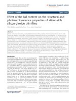
Figure 2: (a) FTIR spectra of citric acid; (b) FTIR spectra of gel
complex (black line) and LaFeO3 (red line).
During the evaporation of the solvent, a reddish-brown gas
corresponding to NO2 comes out of the solution. The above
chemical formula only shows the result of chemical reaction
but the nature of the sol-gel method is not pointed out. In
the used sol-gel method, before creating the solid solution
of LaFeO3 , the La and Fe ions have been presented in a
gel complex. The Fourier transform infrared (FTIR) spectra
of the citric acid, gel, and LaFeO3 have been measured for
demonstration of the process mentioned above [15].
The FTIR spectra of the citric acid, gel complex, and
LaFeO3 nanoparticles are shown in Figure 2. In Figure 2(b)
(black line), two vibrational bands can be observed at
1572 cm−1 and 1385 cm−1 that are assigned to the stretching
of C–O bonds. The bands occurred at 551 cm−1 and 646
cm−1 are corresponding to Fe–O and La–O bonds, respectively, and the wide band around 3137 cm−1 in Figure 2(b)
(black-line) and 3364 cm−1 in Figure 2(a) correspond to the
hydroxyl group. From the above spectroscopic observations
Advances in Materials Science and Engineering
HOOC
C2 H4
CH
3
500
COOH
400
COOH
Lin (Cps)
(a)
COO
OOC
C2 H4
La
CH
OOC
Fe
COO
C2 H4
CH
COO
C2 H4
COO
CH
COO
300
(1)
200
0
Fe
OOC
C2 H4
(400)
(2)
20
30
40
50
60
70
2θ (deg)
(1) LaFeO3 (500◦ C, 3 h)
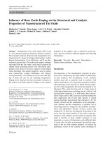
Figure 3: Molecular structure for the citric acid (a) and for a
possible complex of metal ions and citric acid (b) in gel precursor
of LaFeO3 nanoparticles.
(2) LaFeO3 (500◦ C, 10 h)
Figure 5: The powder X-ray diffraction patterns of gel complex
heated at 500◦ C for 3 hours (red line) and for 10 hours (black line).
600
400
(200)
350
500
(2)
300
(2)
Lin (Cps)
Lin (Cps)
(312)
(202)
La
(b)
300
(1)
(004)
200
100
0
(002)
COO
CH
COO
400
(004)
100
La
COO
OOC
(200)
(312)
200
(1)
(400)
(3)
(200)
150
100
(202)
(002)
250
50
(004)
(002)
(312)
(400)
(202)
(3)
0
20
30
40
50
2θ (deg)
60
70
(1) LaFeO3 (300◦ C)
(2) LaFeO3 (500◦ C)
(3) LaFeO3 (700◦ C)
20
30
(1) LaFeO3 (300◦ C)
40
50
2θ (deg)
60
70
80
(2) LaFeO3 (500◦ C)
(3) LaFeO3 (700◦ C)
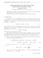
Figure 4: The powder X-ray diffraction patterns of gel complex
heated at 300◦ C (line 1); 500◦ C (line 2); 700◦ C (line 3) for 3 hours.
Figure 6: The powder X-ray diffraction patterns of hydroxide gel
heated at 300◦ C (line 1); 500◦ C (line 2); 700◦ C (line 3) for 3 hours.
it was suggested that the as-prepared gel consists of an
intermediate/complex of citric acid, water, and metal ions.
On the basis of the above FTIR results, the expected
molecular structure of the complex of metal ions and citric
acid is shown in Figure 3.
Figure 4 shows the XRD patterns of the nano-sized
LaFeO3 powders obtained after heating at different temperatures of 300◦ C (line 1), 500◦ C (line 2), and 700◦ C (line 3)
for 3 hours. At 700◦ C the XRD pattern shows that the major
phase is LaFeO3 with orthorhombic crystalline structure.
˚ b = 5.5497 A;
˚ c =
The lattice parameters are a = 5.546 A;
◦
˚
7.8573 A. The gel complex which was heated at 500 C for 3
hours has not yet changed to the LaFeO3 phase, as shown
in Figure 4 (line 2) and Figure 5 (red line). It seems to be
amorphous, but with further heating at 500◦ C for 7 hours,
the LaFeO3 phase was completely formed (Figure 5—black
line). Figure 6 shows the XRD pattern of LaFeO3 prepared
by the co-precipitation method. The complex precipitate was
heated at different temperatures for 3 hours. The phase states
are similar to the case of the sol-gel method (Figure 5). The
XRD patterns of hydroxide gel show that the LaFeO3 phase
does not appear at 300◦ C or 500◦ C; however, at 700◦ C a
major phase as LaFeO3 is formed (Figure 6).
The average crystalline particle size calculated from
Scherrer’s formula D = kλ/B cos θ is about 30 nm, where D is
the average size of crystalline particle, assuming that particles
are spherical, k = 0.9 [14], λ is the wavelength of X-ray
radiation, B is full width at half maximum of the diffracted
peak, and θ is angle of diffraction.
The particle size and morphology of the calcined powders examined by TEM and SEM are shown in Figures 7(a),
7(b), and 8, respectively. It can be estimated from these
figures that the particle size is varying from about 10 to
30 nm.
The magnetic properties of the samples were examined
by Vibrating Sample Magnetometer (VSM) in the field
4
Advances in Materials Science and Engineering
(a)
(b)
Figure 7: TEM (a) and SEM (b) micrographs of LaFeO3 prepared by sol-gel method, followed by calcining process at 700◦ C.
1.6
1.2
M (emu/g)
0.8
0.4
0
−0.4
−0.8
Figure 8: SEM micrograph of nano-LaFeO3 prepared by highenergy milling method.
−1.2
−1.6
−15000 −10000 −5000
0
5000
10000
15000
H (Oe)
LaFeO3
0.25
Figure 10: The M(H) curve at room temperature of nano-LaFeO3
prepared by sol-gel method.
M (emu/g)
0.2
0.15
0.1
0.05
0
300
400
500
600
700
800
T (K)
LaFeO3
Figure 9: The M(T) curve of nano-LaFeO3 prepared by sol-gel
method.
of 13.5 kOe from room temperature to 800 K. The Curie
temperature determined by the M(T) curve (Figure 9) is
around 730 K, which is corresponding to the peak in the DSC
curve at about 457◦ C (Figure 1). The M(H) curve of nanoLaFeO3 prepared by sol-gel method is shown in Figure 10.
As for the sample prepared by high-energy milling the
powders after milling were heated at 500◦ C in 3 hours to
eliminate inner stress in the samples. Figure 8 shows the
SEM image for the LaFeO3 powder after milling and heat
treatment. The average size of particle is about 50 nm. The
M(H) curve of nano-sized LaFeO3 prepared by milling
method is shown in Figure 11.
It is well known that the perovskite LaFeO3 displays antiferromagnetic and insulator behavior in room temperature
[16]. However, the M(T) and M(H) curves of the prepared
LaFeO3 show that LaFeO3 exhibits weak ferromagnetism. It
may be caused by the antiferromagnetic order with canted
spins [17]. In addition, during heating at high temperature
some couples of Fe3+ -Fe2+ may be appeared in LaFeO3 due
to the losing of oxygen. The difference between magnetic
moment of Fe3+ ions (5 μB) and Fe2+ (4 μB) has contributed
to magnetic behaviors of the samples and they became an
electrical conducting materials as semiconductor.
The parameters of hysteresis loop of the samples prepared by sol-gel and milling methods are listed in Table 1.
The results listed in the above table show that the preparation method and particle size influence on the magnetic
properties. Although after milling the samples have been
Advances in Materials Science and Engineering
5
Table 1: The parameters of hysteresis loop of the samples prepared
by sol-gel and milling methods.
0.4
0.3
Mm (emu/g) at
H = 13.5 kOe
Mr (emu/g)
Hc (Oe)
S = Mr /Mm
1.464
0.443
0.078
92.6
0.05
0.063
198.9
0.14
0.2
M (emu/g)
Parameters
Sol-gel method
Milling method
(Particle size of 30 nm) (Particle size of 50 nm)
0.1
0
−0.1
−0.2
−0.3
0.6
0.5
−0.4
−1.5
0.4
−1
−0.5
0
H (T)
0.3
M (emu/g)
0.2
0.5
1
1.5
M fit
M experiment
0.1
0
Figure 12: The result of the fitting of the M(H) curve of the
nano-LaFeO3 prepared by sol-gel method based on the Langevin
function.
−0.1
−0.2
−0.3
−0.4
−0.5
−0.6
−15000 −10000 −5000
0
5000
10000
15000
H (Oe)
where M sp (H) is the contribution from the superparamagnetic (sp) nanoparticles (single domain), M f (H) is the
contribution of ferromagnetic ( f ) nanoparticles (multiple
domains):
LaFeO3
M f (H) =
Figure 11: The M(H) curve at room temperature of nano-LaFeO3
prepared by high-energy milling method.
annealed, it seems that the inner press could not be
eliminated completely; thus the magnetization Mm of the
sample prepared by milling method is less than that of the
samples prepared by sol-gel method. The particle size of the
powders prepared by the milling method is larger than the
one obtained by the sol-gel method. The bigger particles give
a higher coercivity Hc . This is in good agreement with the law
(Hc ∼ D6 ) of the nanomagnetic particles [18, 19]. It is noted
that the nanosized, and single-domain ferromagnetic powder
could be superparamagnetic with Hc = 0 and Mr = 0;
S = (Mr /Ms ) = 0 [20]. If the prepared nano-sized powder
has some of particles with multiple domain sizes, Hc , Mr , and
S will differ from zero. The larger particle size gives higher S
and the ferromagnetic behavior is more clear. That is why
we suggested that the ratio S = Mr /Ms could be used as a
functionally parameter for evaluating the homogeneity on
dimension of nanoparticles and the limit of single domain
size of the magnetic nano-sized powder materials.
As mentioned above, the prepared nano-sized LaFeO3
powder is weakly ferromagnetic (Mr =
/ 0). It is a multidisperse system consisting of the single-domain and
multiple-domain particles. The magnetization of the sample
is considered as the sum of two terms:
M(H) = M sp (H) + M f (H),
(2)
f
2Ms
H ± Hc
πS
tan−1
tan
π
Hc
2
f
,
(3)
f
Ms : saturation magnetization of ferromagnetic phase (Ms =
Mr /0.866). S: rectangular coefficence of ferromagetic hysteresis loop.
The noninteraction magnetization process of the superparamagnetic monodisperse nanoparticles can be shown by
the expression:
mH
M(H) = M(∞)L
,
(4)
kB T
where m is magnetic moment and L(x) = coth(x) − 1/x is the
Langevin function, x = mH/kB T, [21]. To take into account
the effects of size dispersion that are always presented in
any real system, the magnetization of superparamagnetic
particles, in this case, it is better to use the expression:
M sp (H) = M sp (∞)
j
f mj L
mjH
.
kB T
(5)
m j is magnetic moment of the particle, f (m j ) is weighted
terms in Langevin functions [22].
It is suggested that the particles are spherical shape, the
distribution of particle size f (D) is shown by the expression
[23]:
⎛
2
⎞
1
ln (D/D) ⎠
exp⎝−
f (D) = √
,
2σ 2
2πσD
(6)
where σ is standard deviation and D is the average particle
size. f (m j ) can be calculated from D. Figure 12 shows
6
the Langevin function fitting result for the magnetization
curve of the nano-sized LaFeO3 .
4. Conclusion
The nano-sized LaFeO3 has been successfully prepared by
different methods. The particle size of nano-LaFeO3 is
varying from about 10 to 50 nm depending on the preparation method. The prepared nano-LaFeO3 exhibited a ferromagnetic behavior and the particle size influences the magnetic properties of nano-LaFeO3 . The M(H) curve was well
fitted by Langevin function. We have proposed that by using
parameter S = Mr /Ms one could evaluate the homogeneity of
the dimensions of nanoparticles and the critical size of single
domain of the nano-magnetic materials.
Acknowledgment
This work was supported by Vietnam’s National Foundation
For Science and Technology Development (NAFOSTED),
with the project code “103.03.69.09”.
References
[1] V. Caignaert, A. Maignan, and B. Raveau, “Up to 50 000 per
cent resistance variation in magnetoresistive polycrystalline
perovskites Ln2/3 Sr1/3 MnO3 (Ln=Nd; Sm),” Solid State Communications, vol. 95, no. 6, pp. 357–359, 1995.
[2] N. Gayathri, A. K. Raychaudhuri, and S. K. Tiwary, “Electrical
transport, magnetism, and magnetoresistance in ferromagnetic oxides with mixed exchange interactions: a study of the
La0.7 Ca0.3 Mn1−x Cox O3 system,” Physical Review B, vol. 56, pp.
1345–1353, 1997.
[3] H. Taguchi, M. Nagao, and M. Shimada, “Mechanism of
metal-insulator transition in the systems (Ln1−x Cax )MnO3−δ
(Ln: La, Nd, and Gd) and (Nd0.1 Ca0.9− y Sr y )MnO2.97 ,” Journal
of Solid State Chemistry, vol. 97, no. 2, pp. 476–480, 1992.
[4] Md. A. Choudhury, S. Akhter, D. L. Minh, N. D. Tho, and N.
Chau, “Large magnetic-entropy change above room temperature in the colossal magnetoresistance La0.7 Sr0.3 Mn1−x Nix O3
materials,” Journal of Magnetism and Magnetic Materials, vol.
272, pp. 1295–1297, 2004.
[5] K. Iwasaki, T. Ito, M. Yoshino, T. Matsui, T. Nagasaki, and
Y. Arita, “Power factor of La1−x Srx FeO3 and LaFe1− y Ni y O3 ,”
Journal of Alloys and Compounds, vol. 430, no. 1-2, pp. 297–
301, 2007.
[6] M.-H. Hung, M. V. M. Rao, and D.-S. Tsai, “Microstructures
and electrical properties of calcium substituted LaFeO3 as
SOFC cathode,” Materials Chemistry and Physics, vol. 101, pp.
297–302, 2007.
[7] D. Bayraktar, F. Clemens, S. Diethelm, T. Graule, J. Van herle,
and P. Holtappels, “Production and properties of substituted
LaFeO3 -perovskite tubular membranes for partial oxidation of
methane to syngas,” Journal of the European Ceramic Society,
vol. 27, no. 6, pp. 2455–2461, 2007.
[8] K. Iwasaki, T. Ito, M. Yoshino et al., “Power factor of
La1−x Srx FeO3 and LaFe1− y Ni y O3 ,” Journal of Alloys and
Compounds, vol. 430, pp. 297–301, 2007.
[9] P. Dinka and A. S. Mukasyan, “Perovskite catalysts for the
auto-reforming of sulfur containing fuels,” Journal of Power
Sources, vol. 167, no. 2, pp. 472–481, 2007.
Advances in Materials Science and Engineering
[10] M. Yang, A. Xu, and H. Du, “Removal of salicylic acid on
perovskite-type oxide LaFeO3 catalyst in catalytic wet air
oxidation process,” Journal of Hazardous Materials B, vol. 139,
pp. 86–92, 2007.
[11] X. P. Dai, R. J. Li, C. C. Yu, and Z. P. Hao, “Unsteady-state
direct partial oxidation of methane to synthesis gas in a fixedbed reactor using AFeO3 (A = La, Nd, Eu) perovskite-type
oxides as oxygen storage,” Journal of Physical Chemistry B, vol.
110, no. 45, pp. 22525–22531, 2006.
[12] M. Søgaard, P. V. Hendriksen, and M. Mogensen, “Oxygen
nonstoichiometry and transport properties of strontium substituted lanthanum ferrite,” Journal of Solid State Chemistry,
vol. 180, no. 4, pp. 1489–1503, 2007.
[13] A. D. Jadhav, A. B. Gaikwad, V. Samuel, and V. Ravi, “A low
temperature route to prepare LaFeO3 and LaCoO3 ,” Materials
Letters, vol. 61, no. 10, pp. 2030–2032, 2007.
[14] G. Shabbir, A. H. Qureshi, and K. Saeed, “Nano-crystalline
LaFeO3 powders synthesized by the citrate-gel method,”
Materials Letters, vol. 60, pp. 3706–3709, 2006.
[15] M. Srivastava, S. Chaubey, and A. K. Ojha, “Investigation on
size dependent structural and magnetic behavior of nickel
ferrite nanoparticles prepared by sol-gel and hydrothermal
methods,” Materials Chemistry and Physics, vol. 118, no. 1, pp.
174–180, 2009.
[16] S. Komine and E. Iguchi, “Dielectric properties in LaFe0.5 Ga0.5
O3 ,” Journal of Physics and Chemistry of Solids, vol. 68, no. 8,
pp. 1504–1507, 2007.
[17] A. V. Galubkov, E. V. Goncharova, V. P. Zhuze, and I. G.
Manilove, “Transport mechanism in samarium sulfide,” Soviet
Physics Solid State, vol. 7, no. 8, pp. 1963–1967, 1966.
[18] G. Herzer, “Grain size dependence of coercivity and permeability in nanocrystalline ferromagnets,” IEEE Transactions on
Magnetics, vol. 26, no. 5, pp. 1397–1402, 1990.
[19] D. Xue, G. Chai, X. Li, and X. Fan, “Effects of grain size
distribution on coercivity and permeability of ferromagnets,”
Journal of Magnetism and Magnetic Materials, vol. 320, no. 8,
pp. 1541–1543, 2008.
[20] J. P. Vejpravova, D. Niznnasky, J. Plocek, A. Hutlova, and J.L. Rehspringer, “Superparamagnetism of co-ferrite nanoparticles,” in Proceeding of Contributed Paper, Part III (WDS ’05),
pp. 518–523, 2005.
[21] G. F. Goya, T. S. Berquo, and F. C. Fonseca, “Static and
dynamic magnetic properties of spherical magnetite nanoparticles,” Journal of Applied Physics, vol. 94, Article ID 3520, 9
pages, 2003.
[22] F. C. Fonseca, A. S. Ferlauto, F. Alvarez, G. F. Goya, and R. F.
Jardim, “Morphological and magnetic properties of carbonnickel nanocomposite thin films,” Journal of Applied Physics,
vol. 97, Article ID 044313, 7 pages, 2005.
[23] S.-J. Lee, J.-R. Jeong, S.-C. Shin, J.-C. Kim, and J.-D.
Kim, “Synthesis and characterization of superparamagnetic
maghemite nanoparticles prepared by coprecipitation technique,” Journal of Magnetism and Magnetic Materials, vol. 282,
no. 1–3, pp. 147–150, 2004.
Copyright of Advances in Materials Science & Engineering is the property of Hindawi Publishing Corporation
and its content may not be copied or emailed to multiple sites or posted to a listserv without the copyright
holder's express written permission. However, users may print, download, or email articles for individual use.