All optical switch based on 1×3 multimode interference couplers
Bạn đang xem bản rút gọn của tài liệu. Xem và tải ngay bản đầy đủ của tài liệu tại đây (898.24 KB, 11 trang )
Author’s Accepted Manuscript
All-optical switch based on 1×3 multimode
interference COUPLERS
Cao-Dung Truong, Manh-Cuong Nguyen, DuyTien Le, Trung-Thanh Le
www.elsevier.com/locate/osn
PII:
DOI:
Reference:
S1573-4277(16)30060-1
/>OSN414
To appear in: Optical Switching and Networking
Received date: 25 February 2013
Revised date: 25 August 2015
Accepted date: 14 July 2016
Cite this article as: Cao-Dung Truong, Manh-Cuong Nguyen, Duy-Tien Le and
Trung-Thanh Le, All-optical switch based on 1×3 multimode interference
C O U P L E R S , Optical
Switching
and
Networking,
/>This is a PDF file of an unedited manuscript that has been accepted for
publication. As a service to our customers we are providing this early version of
the manuscript. The manuscript will undergo copyediting, typesetting, and
review of the resulting galley proof before it is published in its final citable form.
Please note that during the production process errors may be discovered which
could affect the content, and all legal disclaimers that apply to the journal pertain.
ALL-OPTICAL SWITCH BASED ON 1x3 MULTIMODE
INTERFERENCE COUPLERS
a
a
Cao-Dung Truong, bManh-Cuong Nguyen, cDuy-Tien Le and d*Trung-Thanh Le
Hanoi University of Science and Technology, 1 Dai Co Viet, Hanoi, Vietnam
b
Le Quy Don Technical University, Hanoi, Vietnam
c
d
Hanoi university of Industry, Hanoi, Vietnam
International School (also with International Francophone Institute), Vietnam National
University (VNU), Hanoi, Vietnam
Corresponding author: Email: and Tel: +84-985 848 193
Abstract- In this paper, a new all-optical switch based on 1x3 and 3x3 General Interference (GI)
multimode interference (MMI) structures is proposed. By using nonlinear directional couplers in
two arms of the structure as phase shifters, all-optical switching mechanism can be achieved. In
this study, we use chalcogenide glass on silica for designing the device structure. The switching
states of the device can be controlled by adjusting the optical control signals at the phase
shifters. The transfer matrix method and beam propagation method (BPM) are used for
designing and optimizing the device structure.
Index Terms – All-optical switch, MMI coupler, nonlinear directional coupler, phase shifter
I. INTRODUCTION
Optical communication networks have evolved into the era of all optical switching. In recent
years, various approaches to realize all optical switches have been proposed. In recent years,
there have been some optical switches using MMI structures based on thermo-optic [4], [5] and
electro-optic effects [6], [7]. However, high speed optical communication systems require high
speed optical switches. Therefore, it is particularly necessary to achieve all-optical switches. In
comparison with other optical switches, the MMI based switch has the advantages of low loss,
ultra-compact size, high stability, large fabrication tolerance and greater feasibility for
integration [2].
In addition, chalcogenide (As2S3) waveguides have been proposed as a new platform for
optical signal processing offering superior performance at ultrahigh bit-rates [8]. The high
nonlinearity enables compact components with the potential for monolithic integration, owing to
its large nonlinear coefficient n2 and low two-photon absorption (good figure of merit), the
ability to tailor material properties via stoichiometry, as well as its photosensitivity. These
properties allow the fabrication of photo-written gratings and waveguides [9].
The main aim of this paper is to propose a new structure for 1x3 all-optical switch based on
GI MMI couplers using nonlinear directional couplers as phase shifters. Chalcogenide glass on
silica platform is used for our designs. Nonlinear directional couplers at two outermost arms in
the inter-stage of 1x3 and 3x3 MMI couplers play the role of phase shifters. In order to realize
the phase shifters using nonlinear directional couplers, the control signal is at an arm of the
nonlinear directional coupler, and the information signal is at the other arm. The nonlinear
directional couplers are carefully designed so that the control signal must be separated from
input signals and enters the switching structure from a different single-mode access waveguide
after the switching operation. The aim is to reduce the powers transferring between control
waveguides and information signal waveguides. Numerical simulations using the BPM then are
used to verify the operating principle of the proposed all-optical switch.
II. THEORETICAL ANALYSIS
A. Analytical expression of the MMI coupler
The operation of optical MMI coupler is based on the self-imaging principle [10]. Self-imaging
is a property of a multimode waveguide by which as input field is reproduced in single or
1
multiple images at periodic intervals along propagation direction of the waveguide. MMI
coupler can be characterized by the transfer matrix theory [10], [11]. Following this theory, the
relationship between the input vector and output vector can be obtained. To achieve the required
transfer matrix, the positions of the input and output ports of the MMI coupler must be set
exactly.
In this study, the MMI waveguide has a width of WMMI and the access waveguides have the
same width of Wa. The positions of the input and output ports are located at xi [10]
1W
x i i e , (i=0,1,2)
2 3
(1)
where We is the effective width of the MMI coupler and N is the number of input/output.
In the general interference mechanism, the shortest length of the MMI coupler is set by
LMMI L
(2)
Where Lπ is the half-beat length of two lowest-order modes that it can be written as
L
4n W2
r e
0 1
3 0
(3)
where n r is the refractive index of the core layer, 0 is the free space wavelength.
An 3x3 general interference MMI coupler has length L LMMI L , the resulting amplitudes
from image input i (i=1,..,3) to output j (j=1,..,3) can be given in a compact form
Aij A ji
where Aij
2
1
3
(4)
is the normalized powers of the output images. The phases ij of the equal output
signals at the output waveguides can be calculated by
For
i+
j:
even,
ij 0
( j i)(8 j i)
16
and
for
i+j:
odd
,
(i j 1)(8 j i 1) , where the input ports i (i=1, 2,..,N) are numbered from
16
bottom to top and the output ports j (j=1, 2,..,N) are numbered from top to bottom in the MMI
coupler. 0 0 LMMI
is a constant phase that depends upon the MMI geometry and
2
therefore can be implied in the following calculations.
ij 0
B. Operation principle of the 1x3 all optical switch
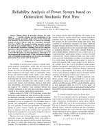
The configuration of our proposed all-optical switching is shown in Figure 1. It consists of 1x3
and 3x3 general interference MMI couplers having the same width. Here, two nonlinear
directional couplers at two outer-arms of the structure are used as two phase shifters. We assume
that input port of the switch is located at position A of the center line and output ports of the
switch are located positions b1, b2, b3 as shown in Figure. 1.
Pcontrol 1
y z
x
LMMI
wa
Input
Pcontrol 2
A
Wa
WMMI
3x3
MMI
Lc
φ1 g
a1
B1
a2
B2
a3
B3
φ2
Directional
Coupler
LMMI
WMMI
3x3
MMI
b1
b2
b3
Output
Figure. 1. A 1x3 all optical switching based on a 1x3 MMI and a 3x3 couplers using directional couplers as phase
shifters
1
A 3x3 GI-MMI coupler can be described by a transfer matrix M which describes the
relationships between the input and output fields of the coupler. The transfer matrix of the 3x3
GI MMI coupler can be expressed as [10], [11]
e j2 /3 e j2 /3
1
1 j2 /3
(5)
M
1
e j2 /3
e
3
j2
/3
j2
/3
1
e
e
The input, output complex amplitudes and phase shifters can be expressed by the following
matrices
e j1
a1
b1
M a a 2 , M b b 2 and 0
a
b
3
3
0
0
0
0 e j 2
0
1
(6)
Where φ1 and φ2 are phase shifter angles at two outermost arms caused by directional couplers
respectively. We have the following relations:
M b = M..Ma
j 1
e 3
b1
1 j 1 3
b2 3 e
b
3
e j 1
e
j
2
3
e j
e
j
2
3
a1
j 2
3
e
. a 2
j 2 a 3
e 3
e
j 2
(7)
The 3x3 MMI coupler with two phase shifters φ1 and φ2 at input port 1 and 3. From equation
(7), the input signal at any input port can be switched to output port 1 if the phase shifts at input
ports 1 and 3 compared to the phase shift at input port 2 are ( , ), switched to output port 2 if
3
5 5
the phase shifts at input ports 1 and 3 compared to the phase shift at input port 2 are ( ,
),
3
3
switched to output port 2 if the phase shifts at input ports 1 and 3 compared to the phase shift at
input port 2 are ( , ). As a result, we find out matched phase shifts for all switching operation
3
states. In summary, phase shifters required to direct the output signals from input signals can be
expressed in Table 1.
TABLE 1. PHASE SHIFTER STATES FOR OPERATION OF THE 1X3 OPTICAL SWITCHES
Input
port
Phase 1
Phase 2
Output
port
A
2
3
0
b1
A
4
3
4
3
b2
A
0
2
3
b3
C. Design of phase shifters using nonlinear directional couplers
1
As mentioned above, the structure of an all optical switching requires two nonlinear
directional couplers based on the Kerr effect [12] as phase shifters at two outermost arms of
optical device as shown in Figure 1. Originally, the nonlinear directional coupler includes two
waveguides that have small distance and full coupling takes place between them in one coupling
length, provided that one or both of them have non-linear behavior. This non-linear behavior can
be guaranteed with high intensity control field which changes the nonlinear refractive index.
When the distance of two nonlinear directional couplers is very small and mode field amplitudes
vary slowly in the z- propagation direction, the interaction of electrical fields in nonlinear
directional couplers complies with coupled mode equations
i
dA
2
2
B 1 A 2 B A
dz
(8)
i
dB
2
2
A 2 B 2 A B
dz
(9)
, Lc is coupling length, A
2Lc
and B are field amplitudes of the control and signal waveguide s of the directional coupler and
γ1, γ2 are nonlinear coefficients describing the self-phase modulation (SPM) and cross-phase
modulation (XPM) effects. Nonlinear coefficient is determined as follows
Where κ is the linear coupling coefficient, it is determined by
2n 2
0 Aeff
(10)
Here λ0 is wavelength in the vacuum, n2 is nonlinear refractive index of the waveguide, Aeff is
the effective modal cross–section area. Under the effect of self-phase modulation in the
nonlinear directional coupler, the phase in directional coupler can be changed proportional to the
intensity of input of electrical fields of waveguides. Nonlinear phase shifts in the directional
coupling waveguide can be expressed by
1
2n 2 Lc Is 2I c1
0
(11)
2
2n 2 Lc Is 2I c2
0
(12)
where I c1 , I c2 are field intensities of the control signal 1 and 2 waveguides respectively; I s is
field intensity of the signal waveguide at outermost arms. In the phase matched case when the
input wavelength and the refractive index of two waveguides are identical, maximum coupling
will take place.
III.
SIMULATION RESULTS AND DISCUSSIONS
A. Simulation results
In this study, we use the chalcogenide glass As2S3 for designing the whole device. The
material used in core layer of the proposed optical switching structure is chalcogenide glass
As2S3 with refractive index nr=2.45. The silica material SiO2 used in cladding layer has
refractive index nc =1.46. As2S3 (arsenic trisulfide) is a direct band-gap, amorphous
semiconductor. By using a highly controlled deposition process, a photo-polymerizable film of
As2S3 can be deposited on standard silica glass substrates. Chalcogenide As2S3 is chosen due to
its advantages. For example, it is attractive for high rate photonics integrated circuits, especially
attractive for all optical switches in recent years because of the fast response time associated
with the near-instantaneous third order nonlinearity allows flexible ultrafast signal processing
[13]. In- addition, the chalcogenide glass supports the operation of wavelengths range in the
windows 1.55μm; and As2S3 material has a high refractive index contrast to allow for a high
confinement [14] of light also ultra-compact size. Therefore, it is useful and important for large
scale integrated circuits. The other advantage of the chalcogenide glass is that it has a high
nonlinear coefficient n2 about 2.92× 10⁻⁶μm2/W. From equations (11) and (12), we can see that
phase angle in the phase shifter of the structure increases proportionally in the nonlinear
coefficient and the control field intensity, so if nonlinear coefficient is high then control field
intensity is low when we keep the phase angle constant. This would be better for operation of the
1
proposed switch because a very high intensity of the control beam will overwhelm the signal.
Moreover, since the control beam intensity is much higher than the signal beam one, the
nonlinear directional coupler needs an extreme high isolation; so that it is difficult to design and
optimize the proposed structure. Silicon dioxide SiO2 is used in cladding layer because of high
refractive index difference between core and cladding layers that allows for a high confinement
of light and also supports a larger mode numbers in MMI region. In addition, both As 2S3 and
SiO2 materials are available and cheap also they can implement in the practical fabrication.
Recently, these materials are very attractive for ultrahigh bit-rate signal processing applications.
The device used in our designs is shown on Figure 1. Here, we use the TE (Transverse
Electric) polarization and operating wavelength 1550-nm for analyses and simulations. If the
uniformity of the time harmonic of TE-polarized waves can be assumed along the x direction of
Figure 1, the simulation can be done assuming it as a 2D structure. In order to reduce time
consuming but still have accuracy results a 3D device structure is converted to a 2D structure
using the effective index method (EIM) first, then the 2D-BPM method is used for simulations
[15].
The design parameters of the proposed structure are chosen as follows: the width of each 3x3
MMI coupler WMMI is 24μm, the width of access waveguides Wa is 4μm in order for single mode
condition can be obtained, the length of the multimode region LMMI is set as Lπ for the general
interference mechanism and it can be calculated by the mode propagation analysis (MPA)
method is 1259.8μm.
Parameters of the control waveguides are designed as follows: the width is set as Wa; at the
beginning, a straight waveguide has the length of 2059.15μm calculated by using the BPM.
Next, it is connected to a sine waveguide which has the length of 1000μm in z propagation
direction and the distance of 9μm in x-direction. Then it is concatenated to another straight
waveguide. By using the BPM, the length of the straight waveguide of the nonlinear directional
couplers Lc is chosen to be 360μm to satisfy the eliminating condition of the cross transfer
power between control and structure waveguides. Gap g between this straight waveguide and the
outermost arm is small (Figure 1) to enable mode coupling. Finally, a sine waveguide and a
straight waveguide are in turn connected (as shown on Figure 1). We choose the sine waveguide
for two purposes: First, the sine waveguides are used to connect the straight waveguides together
in which it puts a waveguide near outermost arms which link between MMI regions in order to
make a full coupling and a phase shift between nonlinear directional waveguides and the second
aim is that light beam power can be conserved when propagated through it. Both control beams
and input signal beams have the same wavelength, amplitude and polarization state in all of
switching states.
Now we optimize the whole device structure. Firstly, the length LMMI is optimized by the 2DBPM method to find the optimal value by changing the values of the length around L π. Finally,
we find out the optimal value as 1260μm. The optimal gap g between two parallel waveguides of
the directional couplers used as phase shifters can be found by using the BPM. The simulations
are shown in Figure 2. We need to find the optimal value g to minimize the cross transferring
power between outermost arms and the control waveguides and split the total power entering
into one input port equally into 3 arms a1B1, a2B2, a3B3 as Pa1B1, Pa2B2, Pa3B3, respectively. This
can be done by introducing power into ports a1, a2 and a3 and use 2D-BPM method. Due to the
symmetry of the proposed structure, we only need to consider the power inserted into control
waveguide 1. By changing the value of g gradually from 0.09μm to 0.11μm and monitoring and
normalizing the power Pa1B1 as well as Pcontrol1, we choose the optimal value of g as 0.1μm
according to Figure 2.
1
Normalized output power
1
0.98
0.96
in a1-PA1B1
0.94
in a2-PA1B1
in a3-PA1B1
0.92
in a1-Pcontrol1
g=0.1 m
0.9
in a2-Pcontrol1
in a3-Pcontrol1
0.88
0.09
0.095
0.1
g ( m)
0.105
0.11
Figure 2. 2D BPM simulation results for the optimal values of the distance between control and structure
waveguide in two cases: a) In case of the control power is on and b) In case of the control is off
Simulation results implemented by the 2D-BPM method in Figure 3 also show that at the
optimal value of the distance between control and structure waveguides, the coupling power
between them is reduced to the minimum value.
To optimize the operation of the MMI regions in the role of the splitter and combiner as
well as minimize the insertion loss and crosstalk effect, linear taper waveguides are used to
connect between MMI regions and access waveguides. In our design, linear tapers have the
length la=150μm and the widths from 3μm to 5μm are calculated and optimized by BPM
simulations.
a)
b)
Figure 3. 2D BPM simulation results for optimal value of the distance between control and structure
waveguide when: a) the control power is on, the data power off and b) the control power off, the data
power on
As mentioned before in results are shown on the Table 1, when the input field enters the
switch from the input A port, if the phase shift in the first linking arm is 2π/3 radian and the
second linking arm is zero radian, it will switch to output b1 port.
For switching from an input to an output of the structure, we implement numerical simulation
by 2D–BPM method to find optimal values of field intensities of control waveguides. The
simulation has to satisfy two requirements: the first, we find the values of field intensities of
control waveguides to produce exactly matched phase shifts for switching operations; then those
values must be optimized so that the transfer power between signal waveguides and control
waveguides is minimal.
We assume that the normalized input power in optical switching device is set as 1
normalized unit; input field intensity I0 equals 1 GW/cm2. This value is chosen because it can
generate the largest nonlinear phase shift. To reach the switching state from port a1 to port b1,
firstly we find the intensity I1, which is introduced into control waveguide 1 (also see Figure 1),
by varying the intensity slowly. The appropriate result is about 14.38GW/cm2 making phase
shift 2π/3 radian in comparison with the center access waveguide. Secondly, we can also change
the value of the intensity I2, which is introduced into control waveguide 2. The appropriate result
1
is about 450GW/cm2 making phase shift zero radian in comparison with the center access
waveguide. Finally, if we use these results to reproduce the simulation and adjust their values
very slowly around them again, we obtain the optimal values I1=14.38 GW/cm2 and
I2=27.38GW/cm2, respectively. The reason for this is due to the loss when the light travels in the
MMI region and also because the length of MMI region is too long to be operated as a splitter or
a combiner accurately. Table 2 lists optimal field intensities and states of control waveguides
used in two control waveguides.
TABLE 2. POWER AMPLITUDE AND INTENSITTY STATES FOR OPERATION OF THE 1X3 OPTICAL SWITCHES
Input
Output
A
I c1
I c2
2
W/μm
W/μm2
b1
14.38
27.38
A
b2
27.72
50.84
A
b3
27.09
18.73
B. Discussions
In this section, we investigate the performance of the device using the insertion loss and
extinction ratio parameters. The insertion loss (I. L.) and extinction ratio (Ex. R.) [16] are
defined by
P
I.L. dB 10log10 out
Pin
(16)
Phigh
Ex.R. dB 10log10
Plow
(17)
where Pout and Pin are the output and input power of the switch in operation state, Phigh and Plow
are output power levels in ON and OFF states respectively.
Simulation results presented in Figure 4 prove that all of the important parameters of the
proposed optical switch are suitable for all optical switching. Refractive index of As 2S3 in this
design is calculated by Sellmeier’s equation [17]. Calculation results show that when the
wavelength varies from 1545nm to 1555nm, the refractive index of As2S3 varies in a small range
0.006 around refractive coefficient 2.435. This variation is very small so we can be neglected.
Therefore, in all of simulation results, we consider refractive index of chalcogenide glass as a
constant.
Input A àOutput b1
Input A àOutput b2
Input A àOutput b3
Figure 4. Simulation results implemented by BPM method for all switching states of the 1x3 all
optical switches
1
Figure 5 shows the dependency of extinction ratio and crosstalk in 10nm of the wavelength
bandwidth. Results show that extinction ratio of the proposed switch vary from 32dB to 34dB,
whilst crosstalk vary from 26dB to 38dB. Those results are very good for application of the
optical switch.
Extinction Ratio and Crosstalk (dB)
38
36
34
32
30
Extinction Ratio: A --> b1
Extinction Ratio: A --> b2
28
Extinction Ratio: A --> b3
Crosstalk: A --> b1
26
Crosstalk: A --> b2
Crosstalk: A --> b3
24
1545 1546 1547 1548 1549 1550 1551 1552 1553 1554 1555
Wavelength (nm)
Figure 5. Wavelength dependency of the extinction ratio and crosstalk of the proposed switch
Figure 6 describes the wavelength dependence of the insertion loss of the proposed switch.
In 10nm wavelength bandwidth (from 1545nm to 1555nm), results show the variation of the
insertion loss in all of operation states of the proposed switch is not exceed 0.5dB.
As shown in Figure 7, the length and the width dependence of MMI sections in proposal
design structure are simulated by the BPM method. The output power is normalized unit dB by
the input power. Results denoted a variation about 0.4 dB of the output power in a quite large
range 1μm of the width and a range 30μm of the length of MMI regions. Hence, the fabrication
tolerance of proposed design is very large.
0
Insertion Loss (dB)
-0.1
-0.2
-0.3
Insertion Loss: A-->b1
-0.4
Insertion Loss: A-->b2
Insertion Loss: A-->b3
-0.5
1545
1546
1547
1548
1549 1550 1551
Wavelength (nm)
1552
1553
1554
1555
Figure 6. Wavelength dependency of the insertion loss in all operation states of the proposed switch
Clearly, the proposed switch has an ability to switch none blocking from any input ports to
any output ports. In comparison with an existing 3x3 optical switch using a 3x3 fiber coupler,
we can see that the 3x3 fiber coupler cannot switch none blocking between input and output
ports despite having phase shift in each input port [18].
Compared with the existing approach structure in the literature which used the 3x3 MZI
structure and electro-optic effect [19], our proposed structure has a better insertion loss. In
addition, our proposed switch is an all-optical switch that can be useful for all-optical networks
and other all-optical signal processing applications.
1
Normalized output power (dB)
-0.15
-0.2
-0.25
-0.3
A-->b1
-0.35
A-->b2
A-->b3
-0.4
-15
-10
-5
0
Length tolerance (m)
5
10
15
Normalized output power (dB)
0
-0.05
-0.1
-0.15
-0.2
-0.25
-0.3
A-->b1
-0.35
A-->b2
-0.4
-0.5
A-->b3
-0.4
-0.3
-0.2
-0.1
0
0.1
Width tolerance (m)
0.2
0.3
0.4
0.5
Figure 7. Normalized output power on the variation of width and length of MMI regions in all
operation states of the proposed switch: a) the variation of the width and b) the variation of the length
IV.
CONCLUSIONS
A novel all-optical MMI switch is designed and presented in this paper, in which the nonlinear directional couplers are utilized to realize all-optical phase shifters. The proposed structure
can be used as an 1x3 all-optical switch. The optical control signals are used to achieve phase
shift. For the first time, an 1x3 all-optical switch based on 3x3 MMI structures is proposed. The
simulation results show that the switching operation has a very good agreement with the
theoretical analysis. In addition, the fabrication tolerance of the switch is relatively large. The
performance of the switch is also analyzed and it is shown that the proposed all-optical switch
can be useful for all-optical networks in the future.
ACKNOWLEDGEMENTS: This research is funded by Vietnam National Foundation for
Science and Technology Development (NAFOSTED) under grant number “103.02-2013.72"
and Vietnam National University, Hanoi (VNU) under project number QG.15.30.
REFERENCE
[1]
J. Sugisaka, N. Yamamoto, M. Okano, and K. Komori, “Demonstration of a photonic crystal
directional coupler switch with ultra short switching length,” Photonics and Nanostructures
Fundamentals and Applications, vol. 2, no. 1, pp. 1–2, 2008.
[2]
J. Leuthold, P. A. Besse, R. Hess, and H. Melchior, “Wide Optical Bandwidths and High Design
Tolerances of Multimode-Interference Converter-Combiners Comparison with Mode-Analysis,”
Proc. of European Conferenc on Integrated Optics, no. 1, pp. 154–157, 1997.
[3]
L. Cahill, “Optical Switching Using Cascaded Generalised Mach-Zehnder Switches,” TENCON
2005 - 2005 IEEE Region 10 Conference, pp. 1–5, Nov. 2005.
[4]
A. M. Al-Hetar, A. B. Mohammad, A. S. M. Supa’at, and Z. A. Shamsan, “MMI-MZI Polymer
Thermo-Optic Switch With a High Refractive Index Contrast,” Journal of Lightwave Technology,
vol. 29, no. 2, pp. 171–178, Jan. 2011.
1
[5]
W. C. Liu, C. L. Mak, and K. H. Wong, “Thermo-optic properties of epitaxial as optical
modulator,” Optics express, vol. 17, no. 16, pp. 13677–13684, 2009.
[6]
M. Earnshaw and D. Allsopp, “Semiconductor space switches based on multimode interference
couplers,” Journal of Lightwave Technology, vol. 20, no. 4, pp. 643–650, 2010.
[7]
Q. Wang and J. Yao, “A high speed 2x2 electro-optic switch using a polarization modulator.,”
Optics express, vol. 15, no. 25, pp. 16500–5, Dec. 2007.
[8]
M. D. Pelusi, F. Luan, S. Madden, D. Choi, D. A. Bulla, S. Member, and B. J. Eggleton,
“Wavelength Conversion of High-Speed Phase and Intensity Modulated Signals Using a Highly
Nonlinear Chalcogenide Glass Chip,” IEEE Photonics Technology Letters, vol. 22, no. 1, pp.
2009–2011, 2010.
[9]
J. Xu, M. Galili, H. C. H. Mulvad, L. K. Oxenløwe, A. T. Clausen, P. Jeppesen, B. Luther-, S.
Madden, A. Rode, D. Choi, M. Pelusi, F. Luan, and B. J. Eggleton, “Error-free 640 Gbit / s
demultiplexing using a chalcogenide planar waveguide chip,” Opto-Electronics and
Communications Conference, and Australian Conference on Optical Fibre Technology.
OECC/ACOFT, vol. 2, pp. 3–4, 2008.
[10]
M. Bachmann, P. A. Besse, and H. Melchior, “General self-imaging properties in N × N
multimode interference couplers including phase relations.,” Applied Optics, vol. 33, no. 18, pp.
3905–3911, 1994.
[11]
L.Soldano and E.C.M Pennings, “Optical Multi-Mode Interference Devices Based on SelfImaging: Principles and Applications,” Journal of Lightwave Technology, vol. 13, no. 4, pp. 615–
627, 1995.
[12]
M. Danaie and H. Kaatuzian, “Improvement of power coupling in a nonlinear photonic crystal
directional coupler switch,” Photonics and Nanostructures Fundamentals and Applications, vol. 9,
no. 1, pp. 70–81, 2011.
[13]
M. D. Pelusi, F. Luan, S. J. Madden, D. Choi, D. A. P. Bulla, and B. J. Eggleton, “CW pumped
wavelength conversion of 40 Gb / s DPSK and 160 Gb / s OOK signals in a Chalcogenide glass
chip,” OptoElectronics and Communications Conference,14th, pp. 5–6, 2009.
[14]
Y. Shi, S. Anand, and S. He, “Design of a Polarization Insensitive Triplexer Using Directional
Couplers Based on Submicron Silicon Rib Waveguides,” Journal of Lightwave Technology, vol.
27, no. 11, pp. 1443–1447, 2009.
[15]
S.-Y. Tseng, C. Fuentes-Hernandez, D. Owens, and B. Kippelen, “Variable splitting ratio 2 x 2
MMI couplers using multimode waveguide holograms.,” Optics express, vol. 15, no. 14, pp.
9015–21, Jul. 2007.
[16]
A. Bahrami, S. Mohammadnejad, and A. Rostami, “All-Optical Multi-Mode Interference Switch
Using Non-Linear Directional Coupler as a Passive Phase Shifter,” Fiber and Integrated Optics,
vol. 30, no. 3, pp. 139–150, Jun. 2011.
[17]
C. Chaudhari, T. Suzuki, and Y. Ohishi, “Chromatic Dispersions in Highly Nonlinear Glass
Nanofibers,” Proc. of SPIE.Photonic Fiber and Crystal Devices: Advances in Materials and
Innovations in Device Applications, vol. 7056, pp. 1–8, Aug. 2008.
[18]
D. O. Culverhouse, T. A. Birks, S. G. Farwell, and P. S. J. Russell, “3x3 All-Fiber Routing
Switch,” IEEE Photonics Technology Letters, vol. 9, no. 3, pp. 333–335, Mar. 1997.
[19]
M. Syuhaimi, A. Rahman, K. M. Shaktur, and R. Mohammad, “Analytical And Simulation Of
New Electro-Optic 3x3 Switch Using Ti : LiNbO3 As a Wave Guide Medium,” International
Conference on Photonics (ICP), pp. 4–8, 2010.
1