DSpace at VNU: Design and Implementation of high - order digital equalizers for audio signal using matlab and dsk tms 320c6711
Bạn đang xem bản rút gọn của tài liệu. Xem và tải ngay bản đầy đủ của tài liệu tại đây (2.87 MB, 7 trang )
VNU JOURNAL OF SCIENCE, Mathematics - Physics, T.XXII, N01 2006
D E S I G N A N D IM P L E M E N T A T IO N O F H I G H -O R D E R D IG IT A L
E Q U A L I Z E R S F O R A U D IO S IG N A L U S I N G M A T L A B A N D D S K
TM S320C6711
S u n g Ho V a n
D epartm ent o f Electronics & Telecommunication, College o f Technology V N U
A b s t r a c t . In this paper, the transfer function of the seventh order digital
graphic equalizer is calculated. The gain responses of the digital filters, of
individual equalizers and of overall graphic equalizer are designed by MATLAB
and implemented by DSK TMS320C6711. These gains can be controlled
independently by adjusting the parameters c, a and p of each section in the
digital graphic equalizer.
1. I n tr o d u c tio n
In the audio a nd musical in s t r u m e n t s , the equalizers are used to enhance
performance of the t r a n s m i t t e r channels or to improve the quality of sound
reaching to the listeners. A typical equalizer consists of a low frequency shelving
filter a nd t h r e e or more peaking filters with a dju sta ble p a r a m e t e r s to provide
a d ju s tm e n t of t h e overall equalizer frequency response over a broad range of
frequencies in the audio spectrum. In a para m etric equalizer, each individual
p a r a m e t e r can be varied independently without effecting the p a r a m e t e r s of the
other filter blocks in the equalizer. In a graphic equaliz er , its consists of a cascade
of peak ing filters with fixed center frequencies b ut a d ju sta ble gain levels.
The major applications of equalizers are to correct and to improve certain
types of problems t h a t may have occurred during the processing or the transfe r
process a nd to a l t e r or to reduce the noise. The a daptiv e equalizers are basically an
adaptiv e filter FIR with coefficients t h a t are ad ju sted by the LMS algorithm to
compensate c h an n e l distortions caused by intersymbol interference s (ISI).
In th is pa per, allpas s filters are employed to design a nd to realize high order
equalizers for audio a nd musical signals. The purpose of these equalizers is to
increase the de sired frequency components and to reduce the u n desired frequency
components in the sound ran ge by modifying the gain response.
2. S tr u c tu r e o f h ig h o rd er e q u a lizer
A high o r d e r equaliz er is created by connecting a cascade of one first-order
with one or more second-order equalizers . The frequency response of overall
eq ualizer can be controlled by adju sting the center frequencies of each section in the
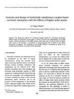
cascade. Figure ( 1) shows the block schema of a cascade of a seventh equalizer
which consist of one first-order and three second-order equalizers. In this block
Su ng Ho Van
48
schema, A,(z) is t r a n s f e r function of the first-order allpass filter, while A 2(z), A 3(z),
A ,(z) a re t r a n s f e r functions of th e second-order allpass filters.
The first-orde r e q u a liz e r is cre ate d by add ing one low-pass filter a nd one highpass filter with th e m u lt i p li e r coefficients Cj/2 and 1/2, respectively a nd is
c h arac terize d by th e following t r a n s f e r function
H , ( z ) = —r ^ - = —L[ l - A | ( z ) ] + - [ l + A | ( z ) ] ;
X(z)
2
2
(1)
where c, is a positive p a r a m e t e r ; Aj(z) is a first-order allpass t r a n s f e r function
given by
A,(z) =
oti “ z
1 —
1-ocjZ
Figure 1. The block schema of a seventh - order graphic equalizer.
The frequency res p o n s e of th is first section Hj(z) can be varied by varying the
values of p a r a m e t e r s Cị a n d Qị. P a r a m e t e r c controls the a m o u n t of boost or cut at
low frequencies, while t h e c o n s t a n t Ơ Ị controls the boost or cut bandwidth .
The c o rre sp on d in g in p u t- o u t p u t relation of the first-order equalizer is
described by following difference equation
y,[n] = -
[(C,+l) + ( 1 -C ,)a 1]x[n] + ị [(0,-1) - ( c , + l ) a 1]x[n-l] + a , y i [n-l] •
(3)
T h a t shows clearly t h a t th e coefficients of difference equatio n can be adjusted
by vary in g th e p a r a m e t e r s Ci a n d ƠỊ.
The t r a n s f e r function of th e ith second-order equalizer is given by
H,(z) = — [l - A, (z)] + ỳ [ l + A; (z)] ,1 = 2 , 3 , 4 ,
2
2
where
(4)
Design a n d I m p l e m e n t a t i o n o f H ig h - o rd e r D i g i t a l . .
A / X _ a i ~ P i ( l +OCj)z 1 + z
A,(z) = - L—1
~
-----------
1 - P j (1 + a jZ
2
49
.
, i = 2, 3, 4
(5)
+aịZ
The rela tio ns (4) and (5) show t h a t the ith e q u a liz e r is c re a t e d by combining
one b a n d p a s s filter with one bandstop filter. T he c e n t e r fr eq uency a n d the 3-dB
band w id th of each filter can be varied by varying t h e v a lue s of p a r a m e t e r s k a a nd
p,. These p a r a m e t e r s of each equalizer can be t u n e d i n d e p e n d e n t l y w i t h o u t effecting
the p a r a m e t e r s of the other sections . Therefore th e frequency a n d m a g n itu d e
response of the overall equalizer can be controlled by a d j u s t i n g t h e s e p a r a m e t e r s .
The c e n t e r frequency CÙQÌ is controlled by th e p a r a m e t e r Pj, b ecause which is
dete rm ined by the following relation
cooi = a r c o s ( P . ) •
The p a r a m e t e r
relation (7)
Qj d ete rm ines
Bw i
(6)
the 3-dB b a n d w i d t h
BW
j of
each e q ualiz er by
arcos
(7)
1+ a :
The magnitude response of the ith equalizer is controlled by para m eter c = H (ej“0)The t r a n s f e r function of th e overall equalizer a s on fig u re(l) given by
Y(z)
H( z ) ~ ™
H
l ( z ) H 2 ( z ) H 3 ( z ) H 4 (z) .
(8)
3. N u m e r ic a l r e s u lts
G a in r e s p o n s e o f e q u a liz e r a = 0 0
20
15
m
s
*
-
y
-20
I
-4Ũ
□
0.5
N o r m a liz e d fr e q u e m c y củ/ ti
10
QJ~
1
IQ .
5
I
0
"vT
0
0 .5
N o r m a liz e d fr e q u e m c y .c o /71
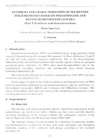
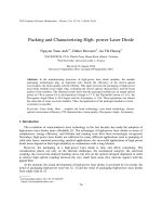
Figure 2. Gain response of the bandpass, band stop and secondorder equalizers with the different values of c, a a nd p.
1
Sung Ho Van
50
A second-order equaliz er is built by adding one b a n d p a ss filter with one
bandstop filter. Figure2 shows the gain responses of these filters a nd of the
equalizer sim ula ted with different p a r a m e t e r s c, a and p. The b a n d p a s s and
bandstop filters are designed with the values of a : ƠỊ =0.8; a 2 =0.5; a 3 =0.2 a nd p =
0.315. These filters are employed for im plem enting two second-order equalizers;
the first equalizer with th e p a r a m e t e r s : C 10 =1.5; C 20 =2.5; C 30 =5; C 40 =0.5; a 3 = 0 .2 ;
p= 0.8 and c , =1; C 2 = 2 ; C 3 =3.5; C 4 =0.7; a, = 0 .8 ; p = 0.315 .
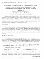
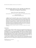
By connecting in cascade of one first-order equalizer with the second-order
equalizers , we can built the higher- order graphic equalizers as plotted on the
figurel. The figure 3 a nd 4 plot the gain responses of the ba ndpass, bandstop
filters, equalizers a nd seventh-order graphic equalizer obtained by synthesizing
these filters and individual equalizers from equations (4) a nd (8 ). Figure3 is plot of
gain responses with the p a r a m e t e r s of values: a = 0.1584; p 2 = 0.809; p3= 0.309; p.j =
- 0.809 and c , = 1.3;
C 2 = 1 .2 ; C 3 = 0.95; C 4 = 1.1 and figure4 with a = 0.7267; p 2
= 0.7071; p 3 = 0.1564;
p 4 = - 0.7071; and c , = 1.3; C 2=2.75;
C3=3.65; C 4 = 3.21.
Figure 5 is the impulse response of graphic equalizer which has frequency response
given on the figure 4.
G ain re sp o n se o f lo w p a ss and b a n d p a ss filGfeam resp on se of h ig h p a ss and ba n d sto p filter
0
0.5
1
N o rm a lize d fre q u e n cy ,củ/ h
G ain re sp o n se o f th e individual eq u a lize rs
"0
0.5
1
N o rm alized fre q u e n cy .co/71
G ain resp on se of th e overal eq ua lize r
3
- 0.5
N o rm a lize d fre q u e n cy
1
, cd/ h
0
0.5
1
N o rm a llize d fre q u e n c y ,03/71
Figure 3. G ain response of the bandpass, b a n dsto p filters,
individual equalizers a nd seventh-order graphic equalizer
with: a = 0 .8 ; p, = 0.809; p3= 0.309; p4= - 0.809; a nd C l = 1.3;
C 2 = 1.7; C3 = 1.55; C4=1.31.
D esign a n d I m p l e m e n t a t i o n o f H ig h - o rd e r D i g i t a l . .
51
G a in re s p o n s e o f lo w p a s s and b a n d p a s s filt& o in re s p o n e o f h ig h p a s s an d b a n d s to p filter
0
05
1
N o r m a liz e d fre q u e n c y .(d/ k
G ain re s p o n s e o f individual e q u a liz e rs
0.5
N o r m a liz e d fre q u e n c y
0
0 5
1
N o r m a liz e d fre q u e n c y .co/n
G a in re s p o n s e o f overal e q u a liz e r
1
,
u/ti
1
N o r m a liz e d fre q u e n c y ,co/w
Figure 4. Gain response of the b a n dp ass, b andstop filters,
individual equalizers and seventh-order graphic equalizer
with: a=0.7267; P2=0.7071; (33=0.1564; (34= - 0.7071; and
C 1=1.3;C 2=2.75; C 3 =3.65;C4 =3.21.
The plots show t h a t the gain response of each equalizer a nd can be regulated
independ ently without effecting the p a ra m e t e r s of th e oth er equalizers and hence
the gain response of overall equalizer can be controlled by reg ulating the
p a r a m e t e r s of each individual equalizer. Therefore, the desired frequency
components can be increased or reduced by reg ula tin g the p a r a m e t e r s c, a or p,
respectively.
Impulse response of overall equalizer
Sample number.n
Sample number.n
Figure 5. Impulse response of the graphic equalizer with
frequency response given on the figure 4 .
52
Sung Ho Van
The coefficients of overall graphic equalizer are printed in the following table
coeff.h =
{
2.2877; 0.2110; -1.2788; -0.2758; -0.1347; 0.4113; 0.1148; -0.3444; 0.3659;
0.2325; -0.1208; -0.1567; -0.2313; 0.1193; 0.1500;-0.0649; 0.0196; 0.0172; 0.0234;
0.0031; -0.0916; -0.0076; 0.0445; 0.0136; 0.0105; -0.0173; -0.0002; 0.0143; -0.0162; 0.0092; 0.0069; -0.0021; -0.0059; 0.0012; 0.0017; 0.0037; -0.0006; -0.0037; 0.0007;
0.0005; -0.0003; -0.0002; -0.0006; 0.0012; 0.0006; -0.0008; -0.0003; -0.0001; 0.0003;
0.0002; -0.0003; 0 0001; 0 0002 ; -0.0000; -0.00QJ; -0.0002; 0.0000;
0.0001; -0.0000;
...0 .0000 }.
4. Im p le m e n ta tio n o f a h ig h - o rd er e q u a liz e r u s in g DSK TMS320C6711
The above se venth-ord er
graphic equalizer can be implemented by
employing DSK TMS320C6711. In this in s t r u m e n t , the four sets of coefficients of
graphic equalizer designed by MATLAB in th e above table is contained in th e file
graphicEQcoeff.h. Both th e inp u t samples and the set of coefficients are
trans formed into the frequency domain. Because the filtering is implemented by
fast convolution with overlap-add method. The complex FFT and IFFT are carried
out on th e floating point DSK TMS320C6711.
The progra m graphicEQ.C which im ple m e n ts this seventh-order equalizer is
tested using an i n p u t voice file Theforce.wav added a sinusoid of the frequency
950Hz which is g e n e r a te d by bass frequency generator. In the o utput of overall
equalizer, this sinusoidal signal is a tt e n u a t e d , because the dip of the gain response
of equalizer occurs a t this frequency component. The slider file graphicEQ.gel
allows to control four frequency bands of overall equalizer independently. The
input, o u tp u t signa ls a nd th eir spectrum of th e overall equalizer can be obtained
with a digital oscilloscope, with a signal analyzer, with th e CCS-window or with an
earphone.
5. C o n clu sio n
By using th e first-order and second-order allpass filters , the lowpass,
highpass, b a n d p a s s a nd bandstop filters are built. These filters are the basic
components to con stitute the individual equalizers. Therefore the overall graphic
equalizer has a very simple stru ctu re. T h a t m ea n s t h a t the impl ementing the FIR
filter is carried ou t rapidly not only on the software b ut also on the hardware.
Because, it allows to reduce a great n u m b e r of computations as well as the num ber
of delays, a d d e r s a nd the coefficient multipliers. The MATLAB and DSK
TMS320C6711 p r o g r a m s p erm it to control flexibly th e p a ra m e te r s of each
individual equaliz er a nd hence the gain response of the overall graphic equalizer
can be controlled flexibly in a desired range of frequency.
D esign a n d I m p l e m e n t a t i o n o f H ig h - o rd e r D i g i t a l . . .
53
R efe r e n c e s
1.
Hồ Văn Sung, x ử lý sô tín hiệu Phương p h á p truyền thống kết hợp với p h n
m ềm M A T L A B . T1&2. Nhà Xuất Bản Giao dục H à Nội 2003, 2005.
2.
Hồ Văn Sung, Thực h à n h x ử lý sô'tín hiệu trên m á y tín h PC với M A T L A B Nhà
Xuất Bản Khoa học và Kỹ T h u ậ t Hà Nội 2005.
3.
TM S320C 6000 CPU a n d Instruction Set Reference Guide, SP RU 189F, Texas
I n str u m e n ts, Dallas, TX, 2005
. 1.
4.G. Pallot, Processeurs de signaux et logique program m able, cours e t TP
CNAM/MEDIAS 2002
4.
S. K. Oppenheim a nd at.all, Discrete-time S ig n a l Procesing, Prentice
1999.
5.
Sanjit K. Mitra, Digital S ig n a l Processing: A Computer- B a se d
McGraw - Hill Irwin 2001.
6.
R. Chassaing, D S P A pplications using c a n d the T M S 3 2 0 C 6 X D SK , J oh n Wiley
& Sons , INC. 2002.
7.
J a n ie s H.McClellan, c . Sidney B u r r u s a nd at., Com puter - B a se d Exercises for
S ig n a l Processing Using M A T L A B 5, Prentic e Hall, 1998.
8.
TM S320C 6000
Code
Composer
I n s t r u m e n t s , Dallas, TX, 2 0 0 1 .
S tu d io
Tutorial,
Hall
Approach,
SP R U 301C ,
Texas