DSpace at VNU: Detection of the location of the hazard during and after the design of combinational circuits
Bạn đang xem bản rút gọn của tài liệu. Xem và tải ngay bản đầy đủ của tài liệu tại đây (832.39 KB, 8 trang )
V N l J Jo ur na l o f S c i e n c c , M a t h e m a t i c s - P hy s i cs 27 ( 2 0 1 1 ) 1 23 - 130
Detection o f the location o f the hazard during and after the
design of combinational circuits
Nguyen Quy Thuong
VNU, Ỉ44 Xuan Thuy, Can Giav, Hanoi, Vietnam
Received 14 April 2011
A bstract. Delay fault and glitch fault cause hazards that are structure hazard and function hazard.
During design process we can use many methods to identify and remove structural hazard [1-2],
[3]. However, with function hazards, determination and remove much more difficult. In this paper
we introduce a new solution to determine the structure hazard by the Truth table - Matrix
mathematics M ethod and method for determining function hazard over how to determine crosstalk
fault [4-71.
Keywords: Structure hazard, function hazard, truth table, multiplication matrix, hazard - algebra,
crosstalk fault, glitch.
1.
Introduction
D etecting, lo c a tin g an d rem oving hazards in a digital circuits is the com pelling w ork o f a designer.
K arn au g h m ap [ 8 ] w a s u sed very often to design digital circuits that are com binational an d sequence;
sy n ch ro n o u s and a sy n ch ro n o u s w ith hazard - free.
John K n ig h t [1], [3], T h u o n g N .Q [2] applied h azard - algebra m ethod for the d esig n o f digital
circuits. I f a c irc u it h a s a hazard, then function o f the circuit will be reduced to one o f th ese form s
XX, X
4- X , x x + x a n d
(x + x)x . H azard - algebra m ethod can detect and m ask h azard in both
co m b in atio n al an d se q u en c e circuits.
T o in v estig a te h a z ard in com binational circuits w ith E X - O R gates, E .c . Tan and M .H . H o [9]
b u ilt m atrix m eth o d th a t g enerate a set o f variables o f all nodes in each gate level o f a circuit
p ro g re ssiv e ly until it reach es the output o f circuit. H ow ever, this m ethod has notyet show exact
location o f h a z ard s a n d w hen dynam ic hazard is d ep endent on static logic
static logic
1
0 “ hazard or d ep en d en t on
- hazard. [4 -7 ], [10,11] sh o w s the test m ethods for crosstalk fault in d u ced glitch
fault. Through crosstalk fault, we have function Hazards can be determined, that appears only
after the circuit was put into use.
In this p a p e r a n e w so lu tio n is pro p o sed to investigate structure h azards in co m binational circuits
that is b a se d on c o m b in a tio n o f truth table, m atrix m athem atics and hazard - algebra to detect structure
E-mail: cp4mua@ yahoo.com.vn
123
N.Q. T huong/ VNU Journal o f Science, Mathematics - Physics 27 (20Ỉ Ỉ) Ỉ23-Ỉ30
124
hazards. T his p ap er also p o in ts out the m ethod o f determ in in g the function hazards via the
determ in atio n o f cro sstalk fault. T he structure o f this paper is as follow s. S ection 2 gives background
on h azard algebra, the d ifferen ce betw een B oolean algebra and H azard algebra; relatio n s betw een
m a t ì x m athem atics and truth table and circuit equation o f function; the test m eth o d s to determ ine the
cro sstalk fault, w hich is to determ in e function hazard in the digital circuit. S ection 3 gives the form al
p ro b le m statem ent to be solved, and an intuitive overview o f the new m ethod as the rules to delect
sừ u c tu re h azards o f so p h isticated form s (in cluding SO P and PO S). S ectio n 4 gives the m ode o f
d e te rm in in g the function h azard in the circuit w as put into use.
2.
Background
T h e potential for a glilch in a com binational circuit is called a hazard. H azards fall into two
classes: function h azards and structural hazards. S tructure hazard could be d etected and rem oved even
d u rin g the design p ro cess b u t function hazard that can delect only the circu it after having taken into
use and the rem oval o f function hazaru is m ore difficult than o f structural hazard. T h is section focuses
on the p ro b le m to o f hazards, h azard algebra, m atrix m athem atics and cro sstalk fault.
2.1. Truth table - M a trix M a th e m a tics M eth o d f o r (he detection a n d location o f s tru c tu re h azards in
d ig ita l circuits
T ru th table - m atrix m ath em atics m ethod w as built to the detection and lo catio n h azards in
co m b in atio n al circuits th at is expressed in eith er sum -of- p ro d u cts (S O P ) form or p roduct-of-sum s
(P O S ) form or both. T h e m ain idea o f this w ork IS to “d ip ” the variables o f fim c iio n on th eir truth ta b le
b y m u ltip ly in g these m atrices c o n fo m i to the rules o f m u ltiplication m atrix (m ath em atics). T he result
o f the m ultiplication is co m p ared w ith definitions o f hazards in hazard algebra [1], [2], [3]. T h at is ^ =
^ (0 ) as static 0 - hazard, ^ ^ t ” -r
( t^ +
^ ( 1 ) as static I - h a za rd aruli^ ^
= ^ e (l) as dynam ic hazard dep endent on static
0
x’
^o(O) , ^ ^
- hazard and dynam ic hazard dependent on
static 1 - hazard, respectively.
T h e p rin cip le o f th is m eth o d as follow s: firstly w e find the variables X th at can cause hazard, and
th en fix value 0 or 1 in variab les Xj X. T o realize this problem w e can “d ip ” the variables, the sum
facto rs or the p roduct term s o f circu it equation on the truth table n variab les b a sed on m ultiplying
eq u a tio n - m atrix w ith truth table - m atrix that conform to the m les o f m u ltip licatio n m atrix
(m ath em atics).
T h e equation ~ m a trix is a m atrix express circuit equation. I f circu it e q u atio n in form SO P, then
c irc u it e q u atio n w ill ho ld s sum factors and if circuit equation in form P O S , then circu it equation w ill
h o ld s p ro d u ct term s. N u m b e r o f sum factors or product te n n s in these circu it eq u atio n s show s n um ber
colum ns o f m atnx, that is, matrix with dim ensions Ixn that IS matrix with 1 row and n colum ns.
T h e M a trix truth tab le is a m atrix express ưxith table o f circu it function. In th is m eth o d the fruth
tab le is rep u te d to be a m atrix n X 2""', it m eans m atrix w ith n colum ns and 2 " “ ‘ row s.
T o m ake n u m b er o f co lu m n s in circuit equation - m atrix equal to n u m b er o f ro w s in truth table matrix we can change this matrix into transpose matrix, that is, let A be an n X 2" ' matrix defined by
th e n u m b e r aịj, then the tran sp o se o f A as A^, denoted
is the 2"'' X n m atrix defin ed b y the n um ber
bjj where bji =
N.Q. Thuong
/
VNU Journal o f Science, Mathematics - Physics 27 (2011) 123-130
125
The algorithm to d etect structure h azard s m com binational circuit o f this m ethod IS given as
follows:
Step 1: C onsider the circuit equation.
I f the circuit equation is co m p licated , then apply De M organ Law to get the sim plest circu it
equation that are circuit equations in form s eith er SO P or PO S or both.
Step 2: C onsider the variables.
_
- Firstly, find the v a n a b le s that can cause hazards. T hey are those variables having b o th X an d X
form , in this case x:= x " a n d x ’:= x' are independent.
Fix X
) values (0,1) by “d ip ” circuit equation n v ariables on the truth table o f circu it
function respectively that realized by m u ltip ly in g tw o m atrices that are circuit equation - m atrix and
truth table - m atrix.
Step Ỉ: C o n sid er the resu lt o f m ultiplication
A fter the variablesX
are fixed value 0 or 1 by “ d ip ” circuit eq u atio n n variables on the
truth table so we get the result o f m ultiplication that either the sum factors t ” . t ’’ = ^ ( 0 ), the c irc u it
con tain s static - 0 hazard, or the product term s t" + t ‘- = ^(1), that IS the circuit con tain s static - 1
hazard, or dynam ic hazard dependent on static logic 0 - hazard
h azard dependent on static logic
1
- hazard ^ = (x"+
) .t" =
4
Ị, =
t". x‘'
= ^o(O) and dynam ic
o(l). or not at all, that is the free h a z ard
circuit.
Step 4: Investigate to rem a in in g variables
T o find the rem aining v ariables X jthat can cause hazards. G o to Step 2, Step 3 until last variab le Xi
is considered.
2.2 To detect crosstalk fa u lt in d u ce d fu n c tio n hazards
A fter the digital circuit is d esig n ed and built, it is alw ays desirable to know w h eth er the c irc u it is
co n sừ u c te d w ithout any faults. Is it IS properly constructed and in use, it m ay be d isable by alm ost any
internal failure. T he process o f applying test and determ ining w h eth er a digital circu it is fault free or
not is know n as fault detection. I f w e know n relationship exists betw een the v arious possible faults
and deviations o f output pattern s, IS term ed as fault location [12] as fu n c tio n hazard. T he in creased
design density in deep - subm icron designs leads to m ore significant in terference b etw een the sig n als
b ecause o f capacitive co u p lin g or crosstalk. C rosstalk can induce bo th B oolean e ư o rs and delay faults.
C ro sstalk - induced pulses are likely to cause errors on hazard - sensitive lines such as inpu ts to
dynam ic gates, clock, set/reset and data inputs to flip - flops. C ro sstalk p u lses m ig h t result in logic
e ư o rs o r degraded voltage levels, w h ich increase propagation delays [6 ].
Studies show that increased co u p lin g effects betw een signals can cause signal delay to in crease
(slow dow n) or decrease (speed up) significantly. B oth conditions can cause errors. Signal slow d o w n
can cause delay fa u lts if a transition is propagated along paths with small slacks. Signal speed - up can
cause race (glitch) conditions i f a tran sitio n s are propagated along short p aths [ 6 ], C rosstalk g litch
o ccu rs w hen there is a sw itch for the signal at one line and the signal at the o th er line is driven steady,
in w h ich case a glitch is form ed at the output o f the steady line. T h e condition for cro sstalk d e la y is
that the signal at both line sw itch es to the opposite direction. T he resu lt is an increase in fransition
tim e [5]. F or tw o line in a circuit, i f the signal ữ an sitio n o f 0 to 1 o r 1 to 0 on a line produces co u p lin g
effects on an o th er line, then the signal line is called an aggressor line, and the o th er line is c a lled a
v ictim line. F or instance, i f the victim line and aggressor line are driven resp ectiv ely b y a static 0 a n d a
126
N.Q. Thuong / VNU Journal o f Science, Mathematics Physics 27 (20Ỉ I) 123-130
-
fast - rising ( 0 to 1 ) transition, then the crosstalk p o sitive glitch is g en erated in th e v ic tim ’s output
signal. If the height o f cro sstalk glitch happens to be larger than the u p p e r - th re sh o ld value o f logic lo w voltage for the give technology, it w ill produce logic failures fu n c tio n a lity p r o b le m ) [ 6 ], W e
c o n sid e r the function hazard in digital circuit, w as put into use, as d etect the c ro ssta lk faults. H ere w e
d efin e crosstalk fault on digital circuits by using B inary D ecision D iag ram (B D D ) o f [ 6 ],
So if w e w ant to detect all form s o f hazard in the circuit so, then w e need to d e te rm in e structure
h a z ard s w ithin the design process and function hazard by determ in in g the cro sstalk fault.
3.
Detection structure hazard in com binational circuits
F rom definitions o f hazard and the algorithm to detect hazard o f this m eth o d in sectio n 2 now w e
can find hazards in circuits for sum - o f - products im plem entation, or for p ro d u c t - o f - sum s
im plem entation, or co m p licated circu it that is not only in forni P O S o r SO P b u t also ho ld all POS and
SO P. L et us consider an EX - O R gate [9] (Fig. 5) as com plex circuit
X ---------- -----------w
Q
Y
Fig. 1. Circuit with EX - OR gate.
S tep 1: F rom this circuit w e have circuit equation:
Q =X Y +X Y +X + W +X Y +X Y +Z
U se the B oolean relatio n s to change circuit equation, w e get:
Q-
+ XỸ)X w + (X + Y)(X + Y)Z
S tep 2: T he C ircuit equation has tw o variables X ( x ^ ',T ^ ) and Y
can cause hazard.
F irstly , consider for X:
X :=
(Y,Z,W): = (OJ) ^
T h e equation Q has tw o sum fa c to r s that are (XY + XY)XW and (X + Y )(X + Y )Z (in form SO P),
b u t in one sum factor hold p ro d u ct term s (PO S). E xam ple: sum facto r (3Õ" +
p ro d u c t term s (X Y + X Y ) and x w
(PO S and SO P). So w e
Can
XỸ)XW hold tw o
create from circu it e q u a tio n Q to one
m afrix M w ith tw o p ro d u ct term s (X Y + X Y ) , X w and one sum factor (X + Y )(X + Y )Z
‘0 1 0 1 0 1 0 1
M.A^ =[(3Ò^ + XỸ)
(XW)
(X + Y)(X + Y )z ] .
0 0
1 1 0 0 1 1
0 0 0 0 1 1 11
N.Q- T huong/ VNU Journal o f Science, Mathematics
-
127
Physics 27 (20Ĩ1) Ỉ23-Ỉ30
Also resu lt o f m u ltip licatio n in a colum n is defined by addition (A oC ) for sum factors and m u ltip ly
(M oC ) for p ro d u ct term s. E xam ple, result o f m ultiplication in first colum n o f b elo w M .A
).
is
. S o w e get:
(x«)
(T ^ )
M .A ^ =
( 0)
(t")
L
L
_L
(T^) (t^^)
(0)
xL
(x » )
(t^ )
Y
(0 )
(0 )
z
0
0
w
0
-1
II
(
t
L
) +
^
t:
(
L
).(
t
t
L
) +
t
L
L
t
I]
Y -1
Y=1
Y=0
z =0
ệ (l)in^
z =0
z=0
^( 0 ) in -
0
W=1
w =0
w =0
C om pare w ith D efinition 1 and 2 w e find out one static - 0 hazard ậ (0 ) in
Y- w
- 1,
z
- 0, one
static - 1 h a z ard ^ ( l ) i n Y = Z = W = 0 and one dynam ic hazard d ep en d en t static - 1 hazard ^ 0 ( 1 ) in
Y = l,z = w = 0.
Step 4: G o to Step 2, Step 3 to co n sid er variable Y :
Y ; = (T»,x^)
(X,Z,W): = (0,1)
M . A ' =[M
1
1
0
1
0
0
1
1
0
0
1
0
0
0
0
1
1
1
0
0
1
1
(x“ )
(x")
(T*-)
(x^-)
(t '-)
(x^-)
X
(x " )
(0 )
(0 )
(t “ )
(t" )
(0 )
(0 )
0
T*-
0
z
w
1
(t“ )
(t" )
0
(t» )(:-'■)+
x =0
x -0
z =0
ệ (0) in • z =0
0
w =0
0
0
Ji
u
^ (l)in <
1
u
u
-
0
W =1
r'-
(T” )(r^ )
0
u
X=1
m in ■z =0
W =1
0
128
we
N.Q. Thuong / VNU Journal o f Science, Mathematics - Physics 27 (2011) 123-130
have
identified
h azard s
^ (1 )
eỊx=Z=W=oỊ,
^ (0 )
eíX=W=l,Z=0)Ị
and
^Q(0)e(x = l, z = w = 0)
0
4.
T hus, the circuit functio n Q has not only dynam ic hazard [9], but also sta tic - 1 h a z ard and static hazard.
Detection Crosstalk induced function hazard
T o determ ine the glitch in the circuit than we need to identify the c ro s s ta lk fau lt. In p rin cip le to
d eterm in e the stuck at fault or cro sstalk fault is to create the test v ector. I f th e re
IS
a fau lt in a circuit
th en the test vectors o f the fault are the input assignm ents that cause th e fau lty c irc u it and norm al
c irc u it (fault - free circuit) to produce different output values. T he test v e c to r d istin g u ish betw een the
g oo d m achine and the faulted m achine. So the test vecto r is built, w h ic h is th e X O R o p e ra tio n o f the
fau lt - free circuit and faulty circuit. F igures 2 [10] tells us m ore about th is in F u n c tio n a l E quivalence
a n d F unctional D om inance (F unctional C ollapsing): F or an input v ector, V , to b e a test for a fault, we
have:
F ,( V ) 0 F ,( V ) = 1
w h ere Fo is the fault - free function and F | is the faulty function, resp e c tiv e ly . C o n s id e r a second fault
th a t p ro d u ces a fault function p 2 . A ccording lo the definition o f fault e q u iv a le n t fau lts h a v e exactly the
sam e tests. T herefore, for tw o faults to be equivalent, w e have
[F„ ( V ) © F, (V )]
e F, (V )] =
0
=> F, (V )] © R ( V ) =
0
Fig. 2. \ ’iewing fault Equivalence.
In [ 6 ] test vector is called test B D D (T est B inary D ecisio n D iag ram ), n o rm a l c irc u it a re know n as
n o rm a l B D D and faulty c irc u it is faulty B D D , so w e have test BD D;
T est B D D = norm al B D D •
faulty B D D + norm al B D D • fa u lty B D D =1
In the test BD D , each inp u t assig n m en t w ith attribute value 1 is a test v e c to r o f th e fault.
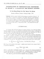
T h e crosstalk fault is one o f the interference effects b e in g cau sed b y p a ra sitic c ap acitan ce and
in d u ctan ce coupling. F o r tw o line in circuit, if the signal tran sit o f 0 to 1 o r 1 to 0 o n e line produces
c o u p lin g effe c ts on an o th er line, then the line is called an ag g resso r line, th e o th e r
line. F ig u re 3 show s the relatio n sh ip betw een aggressor line and v ictim lin e [11].
IS
c a lle d a victim
N.Q. Thuong / VNU Journal o f Science, Mathematics ~ Physics 27 (201Ỉ) 123-Ỉ 30
Y1
Yi-1
Yi
0 victim
Y1
Yi
Yi-1
Y
Yi-1
1 victim
Y1
victim
Yi-1
victim
Y1
Y1
Yi+I
Yi+1
Yi+1
Yi+1
Yn
Yn
Yn
Yn
i
i
victim
129
A
V
victim
victim
Negative glitch
Positive glitch
victim
Slow to fall
Slow to rise
Fig. 3. Maximal aggressor fault model.
T he P ositive g litc h a n d N e g a tiv e glitch in Fig. 3 are function hazards. T h e se H azards can n o t be
rem oved d u rin g th e d e sig n p ro cess, b ecau se they appear only after having taken into use.
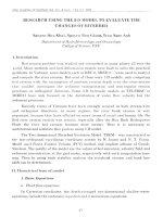
H ere for c irc u it C 1 7 [ 6 ] sh o w n in Fig. 4, w e give an exam ple for test g en eratio n w hen th ere is a
crosstalk fau lt b e tw e e n sig n a l lines C3 and C4 . T h e task o t test g en eration is to se arc h for the inputs
vectors o f circ u it c 17 in o rd e r to d etect the cro sstalk fault. For exam ple, a test v ecto r o f the c ro sstalk
fault is made up o f circuit input vectors Vi = (Xi, X 2 , X 3 , X 4 , X 5 ) = (0, 0, 0, 0, 0) and V 2 = (X|, X2 , X3 , X 4 ,
X5 ) = (0, 0, 0, 0, 1). A p p ly V i and V 2 to the circuit sequentially. I f the circu it o u tp u ts are yi = 0 an d y i
= 0 for V i, y, = 0 a n d y 2 = 1 for V 2 ., then there is not crosstalk. I f the circu it o u tp u ts are yi = 0 a n d yz =
0 for V ,, y, = 1 a n d y 2 = 1 for V 2 ,, then there is crosstalk. T herefore, th is te st v e c to r can d e te c t the
crosstalk fau lt b e tw e e n
63
and
64.
H ere, assum e that C4 ÌS a ag g resso r line and
that a d ow n tra n sitio n (1 to 0 ) in signal line
64
is a victim lin e, and
produces a glitch (1 to 0) in signal line e3, th at is, th ere
is a function h azard .
ei
XI
yi
X3
X2
G3
X4
6 2
X5
63
o64
Fig. 4. C17 Cừcuit.
y2
130
N.Q. T h u o n g / VNU Journal o f Science, M athematics - Physics 27 (2 0 ỈĨ) Ỉ2 3 -Ỉ3 0
5, C onclusion
T h e detection, lo c a te a n d re m o v e th e H a z a rd s o f th e d ig ita l c irc u its is v e ry c ritic a l fo r circuit
d esig n ers. Structure h a z a rd a re d e te c te d an d re m o v e d e v e n d u rin g th e d e s ig n p ro c e s s and th ere w ere
so m e m eth o d s to so lv e th is. T ru th ta b le - M a trix M a th e m a tic s M e th o d p re s e n te d here is a new
so lu tio n to in v estig ate stru c tu re h a z a rd . T h is m e th o d n o t o n ly d e te c te d all k in d s h azards in
combinational circuits but also point out location o f hazards with high accuracy. The Truth table M a trix M ath em atics ca n d e te c t h a z a rd in all c irc u it fu n c tio n s th a t c a n e x p re s s e d b y tru th table. The
rem o v in g structure h a z a rd e rro rs n o d iffic u lty i f w e u se K a rn a u g h m a p [ 8 ] or h a z a rd a lg e b ra [1-3] to
su p p ly red u n d an t term s c o rre s p o n d in g e a c h k in d o f h a z ard . T h e s e fu n c tio n h a z a rd can n o t b e rem oved
d u rin g the design p ro c e ss, b e c a u s e th ey a p p e a r o n ly a fte r h a v in g ta k e n in to use. D u ra tio n o f function
h a z ard can p e rm a n en t, te m p o ra ry o r in te rm itte n t, th u s re m o v in g it is n o t easy. W e can determ ine
fu n ctio n hazard, for e x a m p le th ro u g h th e id e n tific a tio n o f c ro s s ta lk fa u lt as d e s c rib e d above.
R eferences
[1] John Knight, Asynchronous Circuits Races Cycles, and Effect o f Hazards, Electronics Departm ent Carleton
University, April 1, 2006,
[2]N .Q . Thuong, Race and hazard algebra in asynchronous system, K//Ơ Journal o f Science, MathematicsPhysics, VoL24, N o .l (2008) 47.
[3]
John Knight, Glitches and Hazards in D igital Circuits, Electronics D epartm ent, Carĩeton University April 1,
2006.
[4] Shehzad Hasan (advisor: Prof. w . Anheier) (hasan, anheier), Test Pattern Generation and Compaction fo r
Crosstalk induced Gỉitch Fault, ITEM, University o f Bremen, Otto - H ahn - Allee 1, 28359 Bremen,
Germany.
[5] Xiaoyun sun, seonki Kim, Bapiraju Vinnakoda, Crosstalk fa u lt detection by dynam ic Idd, Department of
Electrical and Com puter Engineering U niversity o f M innesola, M inneapolis, M M , 55455.
[6 ] Zhong - Liang Pan, Ling Chen, Guang - Zhao Zhang, Cultural A lgorithm for M inim ization of Binary
Decision Diagram and its A pplication in Crosstalk Fault Detection, International Journal o f Automation and
Computing, 7(1) February (2010) 70.
[7] Kwang - Ting Cheng, C urrent Directions in Autom atic Test - Pattern Generation^ U niversity of California,
Santa Barbara.
[8] M. Karnaugh, A M ap M ethod for synthesis o f com binational logic circuit, Transactions o f the AỈEE,
Communications and Electronics, V ol72:l (1953) 593.
[9] E .c. Tan, M.H. Ho, M atrix m ethod to detect logic hazard in com binational circuit with EX OR gate, Journal
o f Universal Computer Science, vol. 5, 1 1 (1999) 765.
[10] Raja K. K. R. Sandừeddy, Vishwanti D. Agrawal, Diagnostic and D etection Fault CoUapsing fo r Multiple
Output Circuits, D epartm ent o f Electrical and Com puter Engineering A uburn University, AL 36849, USA.
[11] Jin Fu Li, Transistor Stuck - Open Fault, Advanced Reliable systems (ARES) Lab.
[12] Thamarai, S.M. Kuppusam y, K. M eyyappan, T. Enhancing test pattern com pacrion algorithm s for simple
two stage cừcuits, International Journal o f Current Research, v.)l. 4 (2010) 015.