DSpace at VNU: Improved performances in light-emitting diodes based on a semiconductor TiO2 nano cluster buffer layer
Bạn đang xem bản rút gọn của tài liệu. Xem và tải ngay bản đầy đủ của tài liệu tại đây (752.86 KB, 5 trang )
Home
Search
Collections
Journals
About
Contact us
My IOPscience
Improved performances in light-emitting diodes based on a semiconductor TiO2 nano cluster
buffer layer
This content has been downloaded from IOPscience. Please scroll down to see the full text.
2013 Adv. Nat. Sci: Nanosci. Nanotechnol. 4 025013
( />View the table of contents for this issue, or go to the journal homepage for more
Download details:
IP Address: 155.97.178.73
This content was downloaded on 02/12/2014 at 10:58
Please note that terms and conditions apply.
IOP PUBLISHING
ADVANCES IN NATURAL SCIENCES: NANOSCIENCE AND NANOTECHNOLOGY
Adv. Nat. Sci.: Nanosci. Nanotechnol. 4 (2013) 025013 (4pp)
doi:10.1088/2043-6262/4/2/025013
Improved performances in light-emitting
diodes based on a semiconductor TiO2
nano cluster buffer layer
Phuong Hoai Nam Nguyen and Nang Dinh Nguyen
Faculty of Engineering Physics and Nanotechnology, University of Engineering and Technology,
Vietnam National University in Ha Noi, 144 Xuan Thuy Road, Cau Giay District, Hanoi, Vietnam
E-mail:
Received 5 December 2012
Accepted for publication 4 April 2013
Published 30 April 2013
Online at stacks.iop.org/ANSN/4/025013
Abstract
Ultra-thin films of TiO2 nano clusters were fabricated and characterized by field- emission
scanning electron microscopy (FE-SEM) and transmittance measurements. The x-ray spectra
of the TiO2 nano crystals were also studied. The performances of the devices based on the
blended conducting polymer are improved by inserting a semiconducting layer of TiO2 nano
cluster into the emissive poly[9-vinylcarbarzole] (PVK)/ poly[2-methoxy-5(2-ethylhexyloxy)-1,4-phenylenevinylene] (MEH-PPV) and Al cathode. The organic
light-emitting diodes (OLEDs) show high efficiency and good stability with turn-on voltage
lower than 3 V and current density higher than 0.5 mA mm−2 .
Keywords: nano cluster, conducting polymer, blend polymer, organic light emitting diodes
Classification number: 4.02
carriers. It is widely recognized that unbalanced charge
carriers due to higher hole mobility in the hole transporting
layer and slower electron mobility in the electron transporting
layer (ETL) lead to reduced efficiency of OLEDs. It is thus
important to balance the injected charges to improve device
performance. Recently, much work has been done on device
structure especially on the interface of the device [5, 6].
Some organic materials and inorganic insulating materials
have been adopted as hole injection buffer layers inserted
between the indium tin oxide (ITO) anode and the organic
layer, such as copper phthalocyanine (CuPc), polyaniline,
SiO2 , Al2 O3 , and so on [7–11]. In this work ultra-thin films
of TiO2 nano cluster have been fabricated and characterized.
The blend films of poly[9-vinylcarbarzole] (PVK) and
poly[2-methoxy-5-(2-ethylhexyloxy)-1,4-phenylenevinylene]
(MEH-PPV) with optimal weight ratios of PVK/MEH-PPV
have been fabricated and used as the emitting layer.
The TiO2 nano cluster film was inserted at the
interface of this emitting layer. The hole injecting layer
is poly(3,4-ethylenedioxythiophene):poly(styrenesulfonate)
(PEDOT-PSS). It provides an improved efficiency and
good stability as compared to the control device. The
energy-transfer process from PVK to MEH-PPV was
1. Introduction
Organic light-emitting diodes (OLEDs) have been applied
to flat panel display due to the fact that they are easily
manufactured, all solid-state, and have faster switching speed
as well as wider viewing angle, etc. Along with developing
new technology, OLEDs have the potential to substitute
liquid crystal display (LCD) and to become the pacemaker in
the display market. High-performance organic light-emitting
diodes should have a low operating voltage, high efficiency
and relatively good stability. In order to improve the efficiency
of devices, various techniques are available as anode or
cathode modification, annealing and optical coupling [1–4].
For example, cathode modification has been shown to
increase electron injection, so as to improve the electron–hole
balance. As a result, the efficiency of the devices can be
improved. The electroluminescence efficiencies of organic
light-emitting diodes can also be promoted with better charge
injection as well as the balance of the opposite charge
Content from this work may be used under the terms of
the Creative Commons Attribution 3.0 licence. Any further
distribution of this work must maintain attribution to the author(s) and the
title of the work, journal citation and DOI.
2043-6262/13/025013+04$33.00
1
© 2013 Vietnam Academy of Science & Technology
Adv. Nat. Sci.: Nanosci. Nanotechnol. 4 (2013) 025013
P H N Nguyen and N D Nguyen
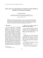
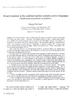
Figure 1. The structure of the OLED.
observed, and thus the emission of MEH-PPV was exclusively
observed when the blended polymer film was photoexcited
by light whose energy was corresponding to the absorption of
PVK. The current–voltage (I–V) characteristics of the devices
were also studied.
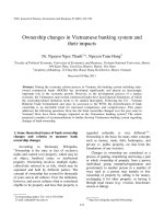
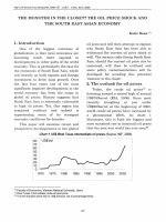
Figure 2. FE-SEM of the TiO2 nano cluster film.
2. Experimental
In this study some kinds of devices have been fabricated
and the devices’ properties were compared with each other.
The TiO2 nano cluster film was introduced between the
emission layer and the cathode. The device configuration
of ITO/PEDOT-PSS/PVK + MEH-PPV/TiO2 /Al is shown in
figure 1.
The TiO2 nanoparticles were available as an aqueous
solution of a 10 wt% suspension of TiO2 in H2 O (purchased
from Sigma-Aldrich). The TiO2 nano cluster films were
prepared by spin-coating at 3000 rpm to investigate the effect
of the electrodes buffer layers on the performance of the
devices. The conducting polymers PVK and MEH-PPV were
purchased from Aldrich Chemical Co. and used as received.
Indium tin oxide (ITO) and Al were used as the anode and
the cathode, respectively. The sheet resistance of the ITO
was 25 cm−1 . Before use, the ITO substrate and glass were
routinely cleaned by ultrasonication in a mixture of acetone
and alcohol, alcohol and deionized water [12]. The blended
polymers were obtained by mixing PVK with MEH-PPV
(PVK:MEH-PPV = 100 : 15) [13] and then the blends were
spin-coated onto the substrates and dried in vacuum at 80 ◦ C
for 2 h. The thickness of the polymer layers were controlled
both by spin speed and by the concentration of polymers
in solvent. The film thickness was measured by using a α
step DEKTAK and found to be around 120 nm. The surface
morphology of the TiO2 nano cluster films were investigated
by using a Hitachi field emission scanning electron
microscopy (FE-SEM) S-4800. The transmittance spectra of
the thin films were obtained from a Jasco UV–Vis–NIR
V570 spectrometer. The photoluminescence (PL) spectra of
the blend conducting polymer films were carried-out by
using a FL3-2 spectrophotometer. The current–voltage (J–V)
characteristics of the devices were measured on an Auto-Lab
Potentiostat PGS-30. All the photophysical measurements
were performed at room temperature in air.
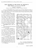
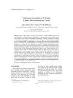
Figure 3. X-ray (a) and transparency (b) spectra of the TiO2 film.
nanoparticles with 20–30 nm in diameter could be determined
to be 3–5 nanoparticle clusters per µm2 .
From the x-ray spectrum of the nanoparticle cluster
TiO2 film (figure 3(a)), the crystal structure of the TiO2
can be determined as rutile with a specific peak [14]. The
transmittance spectrum of the TiO2 film (figure 3(b)) shows
a minimum value at wavenumber of 280 nm, implying that
TiO2 nanoparticle can absorb ultraviolet light.
3. Results and discussion
Figure 2 is the FE-SEM image of the surface of the TiO2 nano
cluster film. It can be seen that the concentration of the TiO2
2
Adv. Nat. Sci.: Nanosci. Nanotechnol. 4 (2013) 025013
P H N Nguyen and N D Nguyen
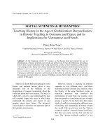
Figure 6. Electrical properties of the electrode buffer layer devices.
Figure 4. Photoluminescence spectra of the conducting polymer
films excited at 325 nm.
obtain the same current density is obviously increased for the
OLEDs with nano cluster TiO2 buffer layer compared with
the device with PEDOT-PSS buffer layer. This is probably
because the PEDOT-PSS thin layer enhances most of the
holes injected from the anode to the emitting layer (PVK +
MEH-PPV) due to its holes transporting property. Figure 6
shows the J–V characteristics of the device using the nano
cluster TiO2 film as anode buffer layer (A) and the multilayer
device (B) combined nano cluster TiO2 film as cathode buffer
layer and PEDOT-PSS as anode buffer layer, respectively.
Figure 6 reveals that the device which combined nano
cluster TiO2 film as cathode buffer layer and PEDOT-PSS as
anode buffer layer, respectively, shows the best performance
with a turn-on voltage about 2.5 V and maximum current
density at 0.7 mA mm−2 (device B). The improvements of
the performance of the device can be considered in order
to explain the behavior of the nanoparticle- cluster-modified
devices. The hole mobility in ordinary PPV is two orders of
magnitude higher than the electron mobility [15], resulting
in a recombination zone that is very close to the aluminum
cathode. In addition, the barrier for hole injection is lower
than the barrier for electron injection. Hence, the J–V
characteristics of the device are mainly determined by the
holes [16]. The nanoparticle clusters, arbitrarily distributed
between the PVK + MEH-PPV and the aluminum layer, create
a randomly nanopatterned cathode interface. This gives rise
to locally enhanced fields again resulting in a higher electron
injection rate, in turn leading to a better charge balance.
The enhanced internal quantum efficiency entails finally an
increased luminescence. This interpretation is supported by
the lower turn-on voltage and the high enhancement factor at
low current densities.
Figure 5. The J–V characteristic of the devices.
Figure 4 compares the PL spectra of bulk films of
PVK and PVK + MEH-PPV. The PL emission from PVK
film excited at 325 nm overlaps with the absorption peaks of
MEH-PPV, and, thus an efficient F¨orster energy transfer can
be anticipated [13].
Figure 5 shows the current density–voltage (J–V)
characterictics of the single layer device (A) and the
multilayer devices using the PEDOT-PSS and nano cluster
TiO2 films as the anode buffer layer (B and C). The multilayer
device (C) was fabricated consisting of a transparent
indium–tin-oxide (ITO) electrode, the nano cluster TiO2 film,
the blend conducting polymer film and an aluminum (Al)
electrode: ITO/TiO2 nano cluster/PVK + MEH-PPV/Al. The
thickness of the nano cluster TiO2 film was estimated to be
around 20–30 nm.
From figure 5 we see that the J–V performances of the
devices are strongly dependent on the presence of the nano
cluster TiO2 film between the anode and the emitting layer. It
can be seen that the current density of the multilayer devices
(B and C) are much higher compared with those of the single
layer device (A) at the same operating voltage. Also, the
threshold field of the multilayer devices is decreased to lower
than 3 V. The single layer device performed very poorly. This
result suggests that the tunneling of charge carriers between
ITO and PVK + MEH-PPV can highly enhance the injection
of holes due to the large potential drop across a thin insulating
layer; hence, the turn-on voltage is reduced and overall current
density is increased. But it shows that the bias voltage to
4. Conclusion
We have fabricated OLEDs with nano clusters TiO2 film
between the emission layer and the cathode. The performance
of the device is improved in decreasing turn-on voltage
(to 2.5 V) and increasing current density (to 0.7 mA mm−2 ),
leading to increase in the efficiency and lifetime of the device.
The nanoparticle clusters increase the electron injection at
the nanoparticle cluster–cathode interface therefore enhancing
the internal quantum efficiency. This effect is particularly
beneficial for solution processed devices, since these
3
Adv. Nat. Sci.: Nanosci. Nanotechnol. 4 (2013) 025013
P H N Nguyen and N D Nguyen
nanoparticles are low cost and easy to handle and might be an
alternative to additional polymer layers for controlling charge
injection and balance.
[5] Bulovic V, Khalfin V B, Gu G, Burrows P E, Garbuzov D Z
and Forrest S R 1998 Phys. Rev. B 58 3730
[6] Kim J S, Friend R H, Grizzi I and Burroughes J H 2005 Appl.
Phys. Lett. 87 023506
[7] Hsiao C C, Chang C H, Hung M C, Yang N J and Chen S A
2005 Appl. Phys. Lett. 88 033512
[8] Aziz H, Popovic Z D, Hu N X, Hor A M and Xu G 1999
Science 283 1900
[9] Karg S, Scott J C, Salem J R and Angelopoulous M 1996
Synth. Met. 80 111
[10] Deng Z B, Ding X M, Lee S T and Gambling W A 1999 Appl.
Phys. Lett. 74 2227
[11] Kurosaka Y, Tada N, Ohmori Y and Yoshino K 1999 Synth.
Met. 102 1101
[12] Tang C W and VanSlyke S A 1987 Appl. Phys. Lett. 51 913
[13] Nguyen P H N and Nguyen N D 2011 Adv. Nat. Sci.: Nanosci.
Nanotechnol. 2 035012
[14] Kumar P M, Badrinarayanan S and Sastry M 2000 Thin Solid
Films 358 122
[15] Hulea I, Van Der Scheer R, Brom H, Langeveld-Voss B, Van
Dijken A and Brunner K 2003 Appl. Phys. Lett. 83 1246
[16] Malliaras G, Salem J, Brock P and Scott C 1998 Phys. Rev. B
58 13411
Acknowledgments
This work was supported by the Asia Research Center and the
Korea Foundation for Advanced Studies, Vietnam National
University in Hanoi within the project code: 55/QD-NCCA.
References
[1] Vanslyke S A, Chen C H and Tang C W 1996 Appl. Phys. Lett.
69 2160
[2] Chen B J, Sun X W, Divayana Y and Tay B K 2005 J. Appl.
Phys. 98 046107
[3] O’Brien D F, Baldo M A, Thompson M E and Forrest S R
1999 Appl. Phys. Lett. 74 442
[4] Chen B J, Sun X W, Wong T K S, Hu X and Uddin A 2005
Appl. Phys. Lett. 87 063505
4