DSpace at VNU: Photoluminescence and I -V Characteristics of Blended Conjugated Polymers ZnO Nanoparticles
Bạn đang xem bản rút gọn của tài liệu. Xem và tải ngay bản đầy đủ của tài liệu tại đây (220.54 KB, 9 trang )
VNU Journal of Science: Mathematics – Physics, Vol. 32, No. 1 (2016) 52-60
Photoluminescence and I -V Characteristics of
Blended Conjugated Polymers/ZnO Nanoparticles
Nguyen Kien Cuong1,*, Nguyen Quoc Khanh2
1
Faculty of Engineering Physics and Nanotechnology, VNU University of Engineering and Technology,
144 Xuan Thuy, Cau Giay, Hanoi, Vietnam
2Faculty of Automobile Technology, Hanoi University of Industry, 32 Road, Tu Liem, Hanoi, Vietnam
Received 30 December 2015
Revised 15 January 2016; Accepted 18 March 2016
Abstract: The investigation of photoluminescence and current-voltage (I-V) characteristics of the
MEH-PPV/PVK blended polymers doped with ZnO nanoparticles (ZnO NPs). First, PVK
polymers were mixed with MEH-PPV in respect to the mass-ratio of 100:15, respectively. And
then the MEH-PPV/PVK composites were doped with ZnO NPs with the mass-ratio of 10 wt%, 15
wt% and 20 wt% of total weight blended polymers. Polymer light-emitting diodes (PLEDs), based
on a hybrid composite, having structure of ITO/ MEH-PPV/PVK/ZnO/Al were made by spincoated, and subsequently vacuum-thermally evaporated.
UV-Vis absorption, photoluminescence properties, SEM micrographs of the hybrid composite
layer as well as I -V characteristics of the PLED based on the MEH-PPV/ZnO-and PVK/ZnOheterojunction were investigated. Results obtained show that the turn-on voltage of the
polymers/ZnO-based PLED is lower than that of the polymers-based PLED without doped ZnO
NPs. This is due to the Auger-assisted energy up-conversion process occurring at the
polymers/ZnO-heterojunction that could enhance the luminescence efficiency of the PLED.
Keywords: PLED, photoluminescence efficiency, MEH-PPV, PVK, SEM, spin coating, thermal
vacuum evaporation
1. Introduction∗
It is commonly recognized that the efficiency of polymer light-emitting devices (PLEDs) strongly
depends on the efficiency of carrier (holes and electrons) injection and of carrier recombination as
well as the balance of hole- and electron-current densities. However, the mobility of holes is generally
much higher than that of electrons in most organic conductive materials. This is one of main reasons
causing imbalanced carrier injection inside the multi-layered PLEDs based on conducting polymers
[1]. Therefore, charge injection balance is an extremely important issue in achieving high efficiency of
the PLEDs [2].
∗
Corresponding author. Tel.: 84-9822114032
Email:
52
N.K. Cuong, N.Q. Khanh/ VNU Journal of Science: Mathematics – Physics, Vol. 32, No. 1 (2016) 52-60
53
Studying a device structure with a charge-balanced operation, one needs to consider both effects
of energy barriers and of e/h mobility on charge injection and charge transport, respectively. Up to
now, some papers have been reported on enhancing the electron injection at the interface of
cathode/electron transport materials (ETM) by using low work function metals [3-4] or balancing the
combination of hole and electron injected from anode and cathode [5-6]. During the device operation,
the imbalanced injection of electrons or holes would result in non-irradiative recombination of the
charge carrier species at the polymer/cathode or the polymer/anode interfaces.
Another approach to overcome the limitation of electron injection and mobility is to combine
conjugated polymers with inorganic semiconductor nanoparticles which have the low energy barrier to
the electron injection and high electron mobility. Zinc oxide nanoparticles (ZnO NPs), a wide-band
gap semiconductor with high electron mobility and low work function, are promising materials for the
LED application [7, 8]. The PLEDs made of a ZnO NPs/MDMO-PPV hybrid polymer composite have
shown electroluminescence (EL) intensity greater than that of the PLED made from the pristine
MDMO-PPV polymer because of the enhancement of charge injection and transport due to adding
ZnO NPs [9]. Moreover, Ajay K. Pandey et. al. [10] have revealed that light emitted by the
hole/electron-recombination in the conjugated-polymer layer at a turn-on voltage below the polymer’s
band gap is observed due to an efficient Auger electron-assisted energy up-conversion process
occurring at rubrene/perylene diimide-heterojunction.
Besides the PLEDs based on the hybrid polymer, blended polymers were also used for enlarging
emission spectrum of PLEDs. The blended polymers of poly(9-vinylcarbazole):poly[2-methoxy-5-(2ethylhexyloxy)-1,4-phenylenevinylene] abbreviated as PVK/MEH-PPV, excited by laser irradiation at
the wavelength of 325 nm, emit the long-wavelength of 300 nm to 600nm due to the Förster resonance
energy transfer [11].
In this paper, we have reported bulk-heterojunction light emitting devices based on blended
conjugated polymers doped with ZnO NPs to enlarge the emission spectrum from the UV to the
visible range. Effects of various amounts of ZnO NPs at polymer/ZnO heterojunction on
photoluminescence (PL) properties were investigated. And also the lower turn-on voltage of the PLED
made of MEH-PPV/PVK/ZnO in the current-voltage (I –V) characteristics than that of MEHPPV/PVK (without ZnO NPs doped), based on a hetero-junction between blended polymers/ doped
ZnO NPs, is found.
2. Experimental
MEH-PPV, PVK conducting polymers and zinc oxide nanoparticles (ZnO NPs) were purchased
from Aldrich Chemical Co. Ltd. Both as p-type conducting polymers dissolved in chloroform solvent,
were mixed with a zinc oxide (ZnO) acting as an n-type inorganic semiconductor to produce hybrid
polymer composites of MEH-PPV/PVK/ZnO. A device for measuring the current-voltage (I–V),
prepared on a glass, had a sandwich structure of ITO/MEH-PPV/PVK/ZnO/Al in which indium tin
oxide (ITO) and aluminum (Al) layers were used as an anode and a cathode electrodes, respectively.
Patterned ITO-electrodes corroded from an ITO-layer on a glass-slide were cleaned in EtOH by
sonication for 10 min each, and dried in an oven at 60 oC for 15 min. The ITO-electrode’s electric
resistance measured is about 60 Ω. Secondly, a compound of PVK and MEH-PPV powder mixed at a
mass-ratio of 100 : 15 (in response to 3.3 mg of PVK and 0.5 mg of MEH-PPV) was dissolved in 1ml
solvent [11] in which an amount of ZnO NPs equal to a mass-ratio of 10%, 15% and 20% of the
polymer compound [12] was added and dispersed in the polymers by sonication in a ultrasonic bath at
room temperature (RT). Hybrid composite films were then made by spin-coating the hybrid compound
solution on both glass-slides and the ITO-electrodes at RT with a rotation speed of 1000 rpm for the
54
N.K. Cuong, N.Q. Khanh / VNU Journal of Science: Mathematics – Physics, Vol. 32, No. 1 (2016) 52-60
60 s. For solvent evaporation and polymer-chain stability, the films were latterly cured in a vacuum
oven at a temperature of 80 oC for 2 hours. Finally, we deposited an Al-cathode on the polymers by
thermal vacuum evaporation of an Al wire on the hybrid composite film at a pressure of 10 -4 Torr, and
a deposition time of 30 s to create devices of ITO/MEH-PPV/PVK/ZnO/Al and ITO/MEHPPV/PVK/Al.
ZnO nanoparticles
(101)
Intensity (a.u.)
(002)
(100)
(110)
(102)
25
35
45
55
2θ
θ (deg.)
(112)
(103)
65
75
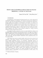
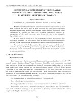
Fig. 1. XRD pattern of ZnO particles.
Structural analysis of ground ZnO NPs was performed by using X-ray Diffractometer (XRD)
model D8 Advance (Bruker, Germany) with Cu Kα radiation, angle step size of 0.01, and count time
of 1.0 s per step. UV-visible absorption spectra of the hybrid composite films were obtained using a
model UV-Vis/NIR-JΛSCO 570 (Japan) spectrometer. Surface images of the hybrid composites of
MEH-PPV/PVK/ZnO were observed on the scanning electron microscope (SEM), Hitachi, Japan.
Photoluminescence (PL) spectra in the rage from 350 nm to 800 nm were collected from a Varian
Cary Eclipse (USA) fluorescence spectrophotometer using a xenon lamp (500 W using a He–Cd cw
laser) as an excitation source of 325 nm and 442 nm, while I-V characteristics of the device were
measured on a PGS-30 potentiometer.
3. Results and discussion
3.1. Structural analysis of ZnO NPs
The X-ray diffraction (XRD) pattern, taken from a ZnO powder before being doped with
polymers, is shown in the Fig. 1. The spectrum is composed of seven distinct peaks, in which, the
XRD peaks at 2θ = 31.740, 36.260 and 610 corresponding to the (100), (101) and (103) planes of ZnO
NPs, respectively. The diffraction peaks suggest that the ZnO NPs are crystalline and have a
hexagonal Wurtzite structure [13]. In addition, their average size calculated from the XRD pattern
using the Scherer’s equation is estimated roughly to be 30 - 40 nm. Doped in the blended polymers,
these ZnO NPs were embedded in the conjugated polymers that formed ZnO/MEH-PPV and
ZnO/PVK heterojunctions.
3.2. UV-Vis absorption analysis
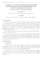
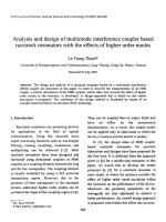
Figure 2 shows absorption spectra of the hybrid composite film of PVK/MEH-PPV/ZnO with the
various mass-ratio of ZnO NPs. It can be seen that there are also two absorption peaks at the range
N.K. Cuong, N.Q. Khanh/ VNU Journal of Science: Mathematics – Physics, Vol. 32, No. 1 (2016) 52-60
55
from 330 nm to 650 nm; the small onset at wavelength of 345 nm belongs to PVK absorption while
the broad peak at 498 is corresponding to the π–π* transition of conjugated MEH-PPV chains [11]. In
addition, both MEH-PPV and PVK absorption decreased with added ZnO concentration was up to
20%, however PVK intensity considerably was reduced while MEH-PPV intensity slightly decreased.
This result provides evidence of the incorporation of ZnO NPs into MEH-PPV/PVK blended
polymers in which doped ZnO NPs do not lead to degrade the optical quality of the composite films
as well as there is no bonding between the blended polymers and ZnO nanoparticles [11-12].
3.3 Photoluminescence spectrum (PL)
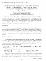
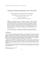
Fig. 3a displays photoluminescence (PL) spectra emitted from the MEH-PPV/PVK/ZnO
composites in the range of 350 to 800 nm using 325 nm as the excitation source at RT with the
different ZnO mass-ratio. The PL spectrum contains a sharp UV emission band centered at 380 nm,
410 nm, and wide green at 560 nm as well as a green-yellow range at around 580 nm. It could be
considered that these emission peaks of the composites are considerably affected by the interfaces of
PVK/MEH-PPV, ZnO/PVK and ZnO/MEH-PPV heterojunctions. In the first component, Förster
energy transfers from the PVK matrix to MEH-PPV one through their interface because the blue
emission spectrum of PVK matrix (PVK’s peak at 410 nm) excited by laser wavelength of 325 nm
overlaps the absorption spectrum of MEH-PPV matrix (its peak at 490 nm). Therefore, green emission
intensity of MEH-PPV matrix at wavelength of 560 nm can be enhanced [11].
1
2
Absorption (a.u.)
1
3
10% ZnO
15% ZnO
20% ZnO
2
3
300
350
400
450
500
550
600
650
Wavelength (nm)
Fig. 2. UV-vis absorption spectra of the blended polymers doped with ZnO NPs.
The present of ZnO NPs, however, affected photoluminescence (PL) emission of blended
polymers. A PL spectrum of the ZnO NPs exhibited a peak at 380 nm in the blue region, which
corresponds to the band gap energy of ZnO. Moreover, the increase in the ZnO NPs concentration up
to the mass-ratio of 20 wt% in the composite film led to form a broad defect-related deep level visible
emission, centered in the green-yellow range at around 580 nm. Normally, these two emission bands
compete against each other; a strong UV luminescence usually coexists with a rather weak visible
emission due to the ZnO NPs growth process.
N.K. Cuong, N.Q. Khanh / VNU Journal of Science: Mathematics – Physics, Vol. 32, No. 1 (2016) 52-60
56
Photoluminescence emitted from PVK/ZnO and MEH-PPV/ZnO heterojunctions was quenched
when compared to that emitted from the pristine polymers. This suggests that the ZnO NPs provided
alternative pathways for excited electrons through polymers/ZnO heterojunctions. Therefore, they
reduce the possibility of radiative emission of the exciton. In the case of the quenching of MEH-PPV
matrix, the alternative pathway is most likely to be a charge transfer process based on the energy
alignment of MEH-PPV matrix and ZnO NPs. As we know, the LUMO of MEH-PPV is - 2.8 eV and
its HOMO is -5.3 eV while the conduction band (CB) of ZnO NPs is - 4.2 eV and their valence band
(VB) is -7.6 eV [12]. During the charge transfer process, when MEH-PPV matrix absorbs photons,
electrons are photo-excited into the lowest unoccupied molecular orbital (LUMO) of this polymer and
leaving behind holes in the highest occupied molecular orbital (HOMO) that produces electron/hole
pairs in MEH-PPV matrix. It is known that the photoluminescence arises from the radiative process
that the excited electrons return to the bottom of valance band. In ZnO-blended polymer
nanocomposites, however, the excited electrons alternatively inject into the conduction band of the
ZnO nanoparticles, because the conduction band edge of ZnO (-4.2 eV) lies below LUMO of MEHPPV (-2.8 eV). This charge transfer at the interface could reduce the transition probability for the
excited electrons from LUMO to HOMO and then reduce the recombination probability of electron
and hole. Therefore, it reduces the intensity of MEH-PPV photoluminescence (quenching) [14].
Similarly, when the charge transfer process at the PVK/ZnO NP interfaces occurs (see Fig. 3a) it
causes large decrease in the emission peak of PVK matrix at 410 nm. The charge transfer at the
interface of hybrid polymers/ZnO heterojunction indicates that the ZnO NPs are effective electron
trappers due to their charge mobility and high electron affinity. Accordingly, the observed large
decrease in the intensity of photoluminescence emission of PVK matrix indicates that the ZnO
nanoparticles in the given nanocomposites are effective electron trappers reducing the number of
excited electrons which could be recombined with holes at the HOMO band.
10% ZnO
15% ZnO
20% ZnO
2
1.
2.
3.
1
3
10% ZnO
15% ZnO
20% ZnO
Intensity (a.u.)
Intensity (a.u.)
1.
2.
3.
2
1
3
350
400
450
500
550
Wavelength (nm)
a)
600
650
500
550
600 650 700
Wavelength (nm)
750
800
b)
Figure 3. Photoluminescence (PL) of the layer MEH-PPV/PVK/ZnO excited by the excited laser at
wavelength of a) 325 nm and b) 442 nm
Figure 3b shows PL spectra of MEH-PPV/PVK/ZnO composites with the different ZnO
concentration under the exposure to the laser at wavelength of 442 nm (λ = 442 nm). The excited
wavelength of 442 nm does not lead to the generation of electron-hole pairs in the bulk of ZnO NPs
and PVK polymer since the photon energy is much smaller than the band gap of two materials.
N.K. Cuong, N.Q. Khanh/ VNU Journal of Science: Mathematics – Physics, Vol. 32, No. 1 (2016) 52-60
57
However, it still promotes an electron to the LUMO band, leaving behind a hole in the HOMO band of
MEH-PPV matrix. The electron and the hole can form a bound state called an exciton which later
diffuses to the MEH-PPV/ZnO interface, and then dissociates. The charge transfer process (similar to
the process mentioned in the previous paragraph) that leads to photoluminescence quenching of MEHPPV matrix when the ZnO NP concentration increases in the composites. Also, the red-shift of PL
emission peaks with the increase in ZnO concentration is due to the longer conjugated polymer chains
made by a larger amount of ZnO NPs added to the MEH-PPV/PVK/ZnO hybrid composites. The PL
spectrum of the MEH-PPV/PVK/ZnO composite in a range 350 nm to 700 nm with two peaks at 380
nm and 570 nm shows emitted blue-green light that expands the emission band of the hybrid
composites from the blue to visible light compared to pristine MEH-PPV and pristine PVK polymers.
3.4. Current-voltage (I-V) characteristics of OLED components
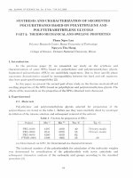
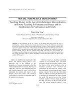
Under forward bias, electrons are efficiently injected from the Al-cathode into the conduction band
(CB) of the ZnO NPs due to the negligible injection barrier between ZnO NPs and the Al-cathode.
Similarly, injected holes from the ITO-electrode also efficiently transferred across the ITO/MEH-PPV
interface due to an injection barrier at a low energy offset of the interface (- 0.5 eV) shown in Fig. 4a.
And then, the injected holes quickly diffused in the MEH-PPV area in which their diffusion-range
depends on the concentration of ZnO NPs.
Although these electrons and holes could be injected into the ZnO NPs and MEH-PPV from the
Al-cathode and the ITO-anode, respectively, they are still confined and accumulated within the ZnO
NPs/MEH-PPV hetero-junction. This might be due to the large energy offset of -1.4 eV between the
LUMO of MEH-PPV and the CB of ZnO NPs as well as the large energy offset (- 2.2 eV) between the
HOMO level of MEH-PPV and the valence band (VB) edge of the ZnO NPs (seen in Fig. 4a), leading
to the electrons and holes to hardly transfer through the MEH-PPV/ZnO NPs heterojunction interface.
In this process, the large energy offset of 1.4 eV between the LUMO of MEH-PPV and the
conduction band of ZnO NPs leads to electron accumulation at the MEH-PPV/ZnO NP interface.
Upon large accumulation of charges at the hetero-junction interface, the electrons at conduction band
of ZnO and holes at the HOMO of MEH-PPV form interfacial charge transfer (CT) excitons. And
then, the resonance energy, released from the non-radiative recombination of these CT excitons, is
resonantly transferred to the proximate electrons on the conduction band of ZnO NPs through an
Auger-assisted energy up-conversion process to produce electrons with sufficiently high energy
overcoming the barrier of 1.4 eV. These proximate electrons absorbing energy were injected into the
LUMO level of MEH-PPV. In addition, the barrier between the VB of ZnO NP and HOMO of MEHPPV is enough to accumulate and confine holes to a range of the MEH-PPV/ZnO interface. Finally,
injected electrons at the LUMO band of MEH-PPV radiatively recombine with accumulated holes at
the HOMO band of MEH-PPV to emit photons with energy, equal to the HOMO-LUMO gap of
MEH-PPV [10, 15-16].
Similarly, the interpretation for accumulation of holes/electrons coupled with the Auger electronassisted energy up-conversion process at the PVK/ZnO NPs hetero-junction interface revealed the
radiative recombine between injected electrons at the LUMO and accumulated holes at the HOMO
band of PVK, resulting in photon emission at the UV range of the PVK.
Furthermore, current-voltage (I-V) characteristics were measured for two devices mainlyconstructed from blended MEH-PPV/PVK with and without ZnO NPs added. It can be seen that the IV spectrum from the blended polymer/ZnO NPs device is identical to that from the corresponding
device without the ZnO NPs. However, the turn-on voltage of the devices having ZnO NPs is
N.K. Cuong, N.Q. Khanh / VNU Journal of Science: Mathematics – Physics, Vol. 32, No. 1 (2016) 52-60
58
significantly lower (approximately 0.8 V shown in Fig 5 left.) than that of the device without ZnO
NPs. This sub-bandgap turn-on voltage is attributed to an efficient Auger up-conversion process at the
polymer/ZnO hetero-interface that was interpreted above. Furthermore, when larger driving voltage
applied, the current of the devices having ZnO NPs highly increased than that of the device without
ZnO NPs and it can be easily seen that the slope of the I-V curve at a point of the ZnO/polymer -based
device is larger than that of the device without ZnO NPs (see Fig.5). Lower turn-on voltage due to
Auger up-conversion process caused by the presence of doped ZnO NPs results in the enhancement of
efficiency of light-emitting heterojunction of PLEDs.
-2.0 eV
-2.8 eV
ITO
- 4.8 eV
MEHPPV - 4.2 eV
-5.3 eV
a)
- 4.2 eV
- 4.2 eV
PVK
ITO
- 4.2 eV
Al
Al
- 4.8 eV
-5.2 eV
ZnO
NPs
ZnO
NPs
-2.0 eV
-7.5 eV
PVK
ITO
- 4.8 eV
-5.2 eV
b)
- 2.8 eV
-7.5 eV
- 4.2 eV
MEHPPV
Al
c)
-5.3 eV
18
16
14
12
10
1.8
1.6
1.4
Current (mA)
Current (mA)
Fig. 4. Schematic energy level diagram of ITO/MEH-PPV/PVK/ZnO/Al device in which each heterojunction of
MEH-PPV/ZnO and PVK/ZnO are illustrated.
8
6
4
2
0
1.2
1
0.8
0.6
0.4
0.2
0
0 0.5 1 1.5 2 2.5 3 3.5 4 4.5 5
Voltage (V)
0
0.5
1
1.5
2
2.5
3
3.5
Voltage (V)
Figure 5. I-V characteristic of the OLEDs based on the structure of
left) ITO/MEH-PPV:PVK:20% ZnO/Al and right) ITO/MEH-PPV: PVK/Al.
4
4.5
5
N.K. Cuong, N.Q. Khanh/ VNU Journal of Science: Mathematics – Physics, Vol. 32, No. 1 (2016) 52-60
59
4. Conclusion
The PLED is based on the structure of ITO/MEH-PPV:PVK:ZnO/Al with MEH-PPV/ZnO
PVK/ZnO and MEH-PPV/PVK hetero-junction. The blended MEH-PPV: PVK based on PLED shows
the broad photoluminescence emission band extending from the range of 380 nm to 580 nm larger
than that of each polymer. And also determining the current-voltage characteristic curves, we found
that the turn-on voltage of the polymers/ZnO-based PLED is lower than that of the polymers-based
PLED without ZnO NPs. It is believed that the lower turn-on voltage, achieved by the added ZnO NPs
than the band-gap voltage of MEH-PPV and PVK polymer is due to an efficient Auger-assisted energy
up-conversion process that occurred at the MEH-PPV/ZnO and PVK/ZnO heterojunction. Therefore,
the addition of ZnO NPs in the ZnO/polymers-based PLED results in the higher efficiency of
luminescence emission compared to the emission of the PLED device based on pristine blended MEHPPV:PVK polymers.
Acknowledgments
This research work is a part of the QG.10.42 project funded by Vietnam National University
(VNU), Hanoi. Advice given by Professor Nguyen Nang Dinh, Faculty of Engineering Physics &
Nanotechnology, School of Engineering & Technology has been a great help in examining
heterojunction effects of PVK/MEH-PPV blended polymers doped with ZnO-NPs on current-voltage
characteristics of the OLED. My special thanks are extended to both Mr. Do Ngoc Chung, a PhD
student and MSc. Truong Van Thinh, a former student of the Faculty of Engineering Physics &
Nanotechnology-VNU for the sample preparation and SEM-image measurement.
References
[1] J.H. Burroughes, D.C. Bradley, A.R. Brown, R. N. Marks, K. Mackay, R. H. Friend, P.L. Burns, A.B. Holmes,
Light-emitting diodes based on conjugated polymers, Nature 347 (1990) 539.
[2] S.Y. Quan, F. Teng, Z. Xu, D.D. Wang, S.Y. Yang, Y.B. Hou, Y.S. Wang, Effect of inorganic nanolayers on
electron injection in polymer light-emitting diodes, Phys. Lett. A 352 (2006) 434.
[3] M.G. Mason, C.W. Tang, L. S. Hung, P. Raychaudhuri, J. Madathil, D.J. Giesen, L.Yan, Q.T. Le, Y. Gao, S. Y.
Lee, L.S. Liao, L.F. Cheng, W.R. Salaneck, D.A. Santos, J. L. Bredas, Interfacial chemistry of Alq3 and LiF with
reactive metals, J. Appl. Phys. 89 (2001) 2756.
[4] X.Y. Deng, S.W. Tong, L.S. Hung, Y.Q. Mo, Y. Cao, Role of ultrathin Alq3 and LiF layers in conjugated
polymer light-emitting diodes, Appl. Phys. Lett. 82 (2003) 3104.
[5] Y.Q. Peng, F.P. Lu, Injection of holes at indium tin oxide/dendrimer interface: An explanation with new theory
of thermionic emission at metal/organic interfaces, Appl. Surf. Sci. 252 (2006) 6275.
[6] F.S. Li, Z.J. Chen, W. Wei, Q.H. Gong, Blue polymer light-emitting diodes with organic/ inorganic hybrid
composite as hole transporting layer, Org. Electron. 6 (2005) 237.
[7] R. Könenkamp, R.C. Word, M. Codinez, Ultraviolet electroluminescence from ZnO/polymer heterojunction
light-emitting diodes, Nano Lett. 5 (2005) 2005.
[8] H. Sun, Q. F. Zhang, J. L. Wu, Electroluminescence from ZnO nanorods with an n-ZnO/p-Si heterojunction
structure, Nanotechnoly 17 (2006) 2271.
[9] J.P. Liu, S.C. Qu, X.B. Zeng, Y. Xu, X. F. Gou, Z.J. Wang, H.Y. Zhou, Z.G. Wang, Fabrication of ZnO and its
enhancement of charge injection and transport in hybrid organic/inorganic light emitting devices, Appl. Surf. Sci.
253 (2007) 7506.
[10] A. K. Pandey and J. M. Nunzi, Up-conversion injection in rubrene/perylene-diimide-hetero-structure
electroluminescent diodes, Applied Physics Letters 90 (2007) 263508.
60
N.K. Cuong, N.Q. Khanh / VNU Journal of Science: Mathematics – Physics, Vol. 32, No. 1 (2016) 52-60
[11] F. Kong, Y.M. Sun, R.K. Yuan, Enhanced resonance energy transfer from PVK to MEH-PPV in nanoparticles,
Nanotechnology 18 (2007) 265707.
[12] Y. J. Choi, H.H. Park, S. Golledge, D.C. Johnson, A study on the incorporation of ZnO nanoparticles into MEHPPV based organic/inorganic hybrid solar cells, Ceramics International 38S (2012) S525.
[13] C. Y. Lee, J. S. Huang, S. H. Hsu, W. F. Su, C. F. Lin, Characteristics of n-type ZnO nanorods on top of p-type
poly (3-hexylthiophene) heterojunction by solution-based growth, Thin Solid Films 518 (2010) 6066.
[14] I. Musa, F. Massuyeau, E. Faulques, T.P. Nguyen, Investigations of optical properties of MEH -PPV/ZnO
nanocomposites by photoluminescence spectroscopy, Synthetic Metals 162 (2012) 1756.
[15] W. Ji, P. Jing, L. Z., D. Li, Q. Zeng, S. Qu & J. Zhao, The work mechanism and sub-bandgap-voltage
electroluminescence in inverted quantum dot light-emitting diodes, Nature.com, scientific reports 4 (2014)
Article No: 6974.
[16] A. K. Pandey and J. M. Nunzi, Rubrene/Fullerene heterostructures with a half-gap electro- luminescence
threshold and large photovoltage, Adv. Mater. 19 (2007) 3613.