DSpace at VNU: Interface charge trap density of solution processed ferroelectric gate thin film transistor using ITO PZT Pt structure
Bạn đang xem bản rút gọn của tài liệu. Xem và tải ngay bản đầy đủ của tài liệu tại đây (547.58 KB, 15 trang )
This article was downloaded by: [Selcuk Universitesi]
On: 09 February 2015, At: 13:31
Publisher: Taylor & Francis
Informa Ltd Registered in England and Wales Registered Number: 1072954 Registered
office: Mortimer House, 37-41 Mortimer Street, London W1T 3JH, UK
Ferroelectrics Letters Section
Publication details, including instructions for authors and
subscription information:
/>
Interface Charge Trap Density of Solution
Processed Ferroelectric Gate Thin Film
Transistor Using ITO/PZT/Pt Structure
Pham Van Thanh
a d
, Bui Nguyen Quoc Trinh
, Phan Trong Tue
b c
, Eisuke Tokumitsu
b c
b e
, Takaaki Miyasako
& Tatsuya Shimoda
b
a b c
a
School of Materials Science , Japan Advanced Institute of Science
and Technology , Nomi , Ishikawa , 923-1292 , Japan
b
ERATO, Shimoda Nano-Liquid Process Project , Japan Science and
Technology Agency , Nomi , Ishikawa , 923-1211 , Japan
c
Green Devices Research Center , Japan Advanced Institute of
Science and Technology , Nomi , Ishikawa , 923-1292 , Japan
d
Faculty of Physics , University of Science, Vietnam National
University , 334 Nguyen Trai, Thanh Xuan , Hanoi , Vietnam
e
Faculty of Engineering Physics and Nanotechnology , University of
Engineering and Technology, Vietnam National University , 144 Xuan
Thuy, Cau Giay , Hanoi , Vietnam
Published online: 13 Aug 2013.
To cite this article: Pham Van Thanh , Bui Nguyen Quoc Trinh , Takaaki Miyasako , Phan Trong Tue ,
Eisuke Tokumitsu & Tatsuya Shimoda (2013) Interface Charge Trap Density of Solution Processed
Ferroelectric Gate Thin Film Transistor Using ITO/PZT/Pt Structure, Ferroelectrics Letters Section,
40:1-3, 17-29, DOI: 10.1080/07315171.2013.813823
To link to this article: />
PLEASE SCROLL DOWN FOR ARTICLE
Taylor & Francis makes every effort to ensure the accuracy of all the information (the
“Content”) contained in the publications on our platform. However, Taylor & Francis,
our agents, and our licensors make no representations or warranties whatsoever as to
the accuracy, completeness, or suitability for any purpose of the Content. Any opinions
and views expressed in this publication are the opinions and views of the authors,
and are not the views of or endorsed by Taylor & Francis. The accuracy of the Content
should not be relied upon and should be independently verified with primary sources
of information. Taylor and Francis shall not be liable for any losses, actions, claims,
proceedings, demands, costs, expenses, damages, and other liabilities whatsoever or
howsoever caused arising directly or indirectly in connection with, in relation to or arising
out of the use of the Content.
Downloaded by [Selcuk Universitesi] at 13:31 09 February 2015
This article may be used for research, teaching, and private study purposes. Any
substantial or systematic reproduction, redistribution, reselling, loan, sub-licensing,
systematic supply, or distribution in any form to anyone is expressly forbidden. Terms &
Conditions of access and use can be found at />
Ferroelectrics Letters , 40:17–29, 2013
Copyright © Taylor & Francis Group, LLC
ISSN: 0731-5171 print / 1563-5228 online
DOI: 10.1080/07315171.2013.813823
Interface Charge Trap Density of Solution Processed
Ferroelectric Gate Thin Film Transistor Using
ITO/PZT/Pt Structure
Downloaded by [Selcuk Universitesi] at 13:31 09 February 2015
PHAM VAN THANH,1,4,∗ BUI NGUYEN QUOC TRINH,2,5
TAKAAKI MIYASAKO,2 PHAN TRONG TUE,2,3 EISUKE
TOKUMITSU,2,3 AND TATSUYA SHIMODA1,2,3
1
School of Materials Science, Japan Advanced Institute of Science and
Technology, Nomi, Ishikawa 923-1292, Japan
2
ERATO, Shimoda Nano-Liquid Process Project, Japan Science and Technology
Agency, Nomi, Ishikawa 923-1211, Japan
3
Green Devices Research Center, Japan Advanced Institute of Science and
Technology, Nomi, Ishikawa 923-1292, Japan
4
Faculty of Physics, University of Science, Vietnam National University, 334
Nguyen Trai, Thanh Xuan, Hanoi, Vietnam
5
Faculty of Engineering Physics and Nanotechnology, University of Engineering
and Technology, Vietnam National University, 144 Xuan Thuy, Cau Giay, Hanoi,
Vietnam
Communicated by Dr. George W. Taylor
(Received in final form December 15, 2012)
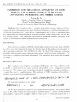
The conductance method was applied to investigate the interface charge trap density
(Dit ) of solution processed ferroelectric gate thin film transistor (FGT) using indium-tin
oxide (ITO)/ Pb(Zr,Ti)O3 (PZT)/Pt structure. As a result, a large value of Dit of MFS
capacitor, i.e., Pt/PZT/ITO, was estimated to be 1.2 × 10¹⁴ eV −1 cm−2. This large Dit
means that an interface between the ITO layer and the PZT layer is imperfect and it is
one of the main reasons for the poor memory property of this FGT. By using transmission
electron microscopy (TEM), this imperfect interface was clearly observed. Thus, it is
concluded that improvement of this interface is critical for better memory performance.
Keywords Ferroelectric; metal-ferroelectric-semiconductor; indium-tin oxide (ITO);
Pb(Zr,Ti)O3 (PZT); ferroelectric gate thin film transistor (FGT); C-V measurement;
interface charge trap density (Dit ); conductance method
1. Introduction
Recently, ferroelectric-gate field-effect transistors using ferroelectric materials as gate insulators have attracted much attention as a nonvolatile memory element with low power
consumption, high speed and high endurance due to their natural ferroelectric properties,
∗
Corresponding author. E-mail:
17
Downloaded by [Selcuk Universitesi] at 13:31 09 February 2015
18
P. V. Thanh et al.
and there are various applications such as wireless IC cards and tools for mobile communication [1, 2]. Many studies of these devices have been conducted since the 1960s
[3, 4]. Among these studies, Si-base ferroelectric gate transistors have been studied most
intensively [5, 6]. However, Si-base ferroelectric gate transistors have the problem of interdiffusion of constituent elements between the ferroelectric layer and the Si substrate
because high crystallization temperature is needed to deposit ferroelectric films leading
to formation of a transition layer at the interface between the Si-substrate and the ferroelectric layer, therefore the interface charge trap density is increased very much when the
crystallization temperature of ferroelectric films is increased [7]. It is well known that the
interfaces between semiconductor channels and gate insulators of field effect transistors
influent much on their electric properties [8–10]; thus, this transition layer leads to poor
electric properties of this transistor. To solve this problem, multi-stacked structures including a buffer layer such as a metal-ferroelectric-insulator-semiconductor (MFIS) [11, 12]
or a metal-ferroelectric-metal-insulator-semiconductor (MFMIS) [13] have been used to
fabricate Si-base ferroelectric gate memory transistors. In the case of the MFIS structure,
C. Y. Chang et al. reported the small value of 3 × 10¹¹eV−1 cm−2 of interface charge trap
density between Si-semiconductor and Dy2 O3 insulator of MFIS structure estimated by
the conductance method [12]. However, a problem of these transistors is charge mismatch
between the ferroelectric layer and the insulator layer. Therefore, partial polarization of a
polarization-electric field (P-E) loop is only used in MFIS-FET structure [14]. That leads
to a small memory window in transfer characteristics even if high operation voltage is applied. In the case of the MFMIS structure, several reports have demonstrated good electrical
properties [5, 6, 13] such as large memory window and good retention time with the large
MIS/MFM area ratio; especially, the small interface charge trap density of 1–2 × 10¹² eV−1
cm−2 calculated by C-V measurement was believed to be one of the major reasons for the
improved electric properties of the MFMIS-FET [6]. However, its structure is complicated
to fabricate, so it is not suitable for low-cost fabrication and high integration.
Therefore, oxide-based ferroelectric gate thin film transistor (FGT) could be one of
the most promising candidates for a low cost memory with high performance, because of
very simple oxide-semiconductor/ferroelectric stacked structure. In addition, as the oxidesemiconductor layer can be deposited directly on the ferroelectric layer, these FGTs can
utilize full ferroelectric polarization without charge-mismatch because the polarization of
the ferroelectric gate insulator can be directly applied to the oxide-semiconductor channel.
Consequently, this type of FGTs could have large memory window with low operation
voltage and improve retention properties. The good properties of these typical FGTs have
been already reported by Tokumitsu et al. [14], Tanaka et al. [15], Miyasako et al. [16]
and Kato et al. [17]. Furthermore, in order to reduce the processing costs, Miyasako et al.
reported the total solution deposition processed-FGT using ITO/PZT stacked structure with
a large memory window and a high ON/OFF current ratio [18]. The effect of the oxidesemiconductor/ferroelectric interface on the electric properties of these FGTs was also
considered. Kato et al.[17] and Kaneko et al. [19] reported the very good interface between
the ZnO layer and the PZT one deposited by PLD method, which was observed by the
HR-TEM. This perfect interface leads to the good electric properties of these FGTs such
as the large on/off ratios of 105, the good data retention properties: it is believed that the
amount of space charge at the ZnO/PZT interface is markedly low. Whereas, Miyasako
et al. reported the existence of the imperfect 4-nm-thick interface between the ITO channel
and the PZT layer of the FGT fabricated by total solution process, which could result
in the large interface charge trap and it was supposed to be a main reason for the poor
retention property [18]. However, the absolute value of the interface charge trap density
(Dit ) between the oxide-semiconductor and the ferroelectric insulator has not yet reported
Downloaded by [Selcuk Universitesi] at 13:31 09 February 2015
Dit of Solution Processed FGT Using ITO/PZT/Pt
19
before although this interface charge trap density (Dit ) would be the best way to confirm
whether a semiconductor/insulator interface is good or not. In order to determine the Dit
between a semiconductor and an insulator, the conductance method extracted from the
admittance measurement of the metal-insulator-semiconductor (MIS) structure is a reliable
method [20], in which SiO2 /Si was used as a standard MIS structure. This method is useful
not only for the Si-based MIS structure but also for the others, such as polyfluorene-based
MIS [21] and Ge-base MIS [9]. In addition, by using the conductance method, the Dit of
the metal-ferroelectric-semiconductor structure was also investigated [22]. Therefore, it is
expected that this method could be used to calculate the Dit of ITO/PZT structure, i.e.,
metal-ferroelectric-semiconductor structure.
In this study, a good FGT was successfully fabricated using solution processed-PZT
and sol-gel ITO as ferroelectric gate insulator and n-type channel, respectively. Electric
properties of this FGT were investigated. The measured capacitance-voltage (C-V) characteristic of Pt/ITO/PZT/Pt (MFS) capacitor exhibited that depletion and accumulation of the
ITO layer were wholly controlled by the huge polarization charge of the PZT-gate insulator.
In particular the interface charge trap density (Dit ) between ITO and PZT was estimated by
using the conductance method.
2. Experimental Methods
170-nm-PZT thin film was prepared on a Pt(111)/Ti/SiO2 /Si substrate by the sol-gel technique. Raw solution of Pb1.2 (Zr0.4 Ti0.6 )O3 was spin coated at a speed of 2500 rpm for 25 s,
then dried at 240◦ C for 5 min, this process was repeated several times to obtain 170-nmthick of PZT film, and then this sample was crystallized at 600◦ C for 20 min in ambient air
by rapid thermal annealing (RTA) system. The excess of the lead was added to compensate
for evaporation loss and to assist the crystallization. Next, the ITO layer with a thickness of
25 nm was deposited by spin-coating using carboxylate-based precursor solution (5 wt%
SnO2 -doped) on the PZT layer and consolidated at 350◦ C in air for 10 min. After that, Pt
source and drain electrodes were sputtered at room temperature and patterned by a lift-off
process. In the next step of fabrication, the ITO channel was patterned by photolithography and dry-etching. Finally, the ITO channel was annealed at 450◦ C in air for 60 min
by RTA. The channel length (LDS ) and channel width (W) were 15 and 60 μm, respectively. Schematic illustrations of Pt/PZT/Pt (MFM), Pt/ITO/PZT/Pt (MFS) capacitors with
1.12 × 10⁻⁴ cm2 area of the top electrodes and a FGT are shown in Fig. 1(a)–1(c).
The crystalline structure of the PZT thin film was identified by X-ray diffraction (M18XHF-SRA) using Cu Kα radiation. The cross sectional image of an
ITO/PZT/Pt structure was observed by the transmission electron microscope (TEM). The
Figure 1. Schematic illustrations of (a) MFM, (b) MFS capacitors and (c) ferroelectric gate thin film
transistor. (Figure available in color online.)
20
P. V. Thanh et al.
polarization-electric field (P-E) curves were measured using the Sawyer-Tower circuit.
The capacitance-voltage (C-V) measurements were performed using Wayne Kerr precision
component analyzer 6440B with 50 mV amplitude of AC signal. The impedance characteristics were carried out by Solartron 1296 Dielectric interface and 1260 Impedance analyzer
in a frequency range of 5 Hz-100 kHz at room temperature with a 50 mV amplitude of
AC signal. These measurements were carried out by applying voltage to the bottom Pt
electrode with the top Pt electrode grounded. The transfer characteristics (IDS -VG ) and
the output characteristics (IDS -VD ) were measured by semiconductor parametric analyzer
(Agilent 4155C).
Downloaded by [Selcuk Universitesi] at 13:31 09 February 2015
3. Interface Charge Trap Density (Dit ) of Metal-InsulatorSemiconductor Capacitor
For analysis of the interface trap, the equivalent circuit of a metal-insulator-semiconductor
capacitor (MIS) is presented as Fig. 2(a) where CD is capacitance of the depleted region
of a semiconductor layer, Cit (ω) is the equivalent parallel interface trap capacitance, Gp (ω)
is the equivalent parallel conductance and Cox is the capacitance of an insulator layer. The
admittance Ys of the semiconductor portion is given by [20]
Ys = j ωCD + Cit (2τit )−1 ln 1 + (ωτit )2 + 2j arctan (ωτit ) = j ωCp + Gp
(1)
Figure 2. (a) Lumped parallel equivalent of circuit of MIS capacitor in depletion of a distribution of
interface traps, (b) equivalent circuit of the MIS capacitor in depletion including series resistance Rs .
Dit of Solution Processed FGT Using ITO/PZT/Pt
21
where equivalent parallel capacitance Cp and conductance Gp of the semiconductor portion
are defined as
Cp = CD + Cit (ωτit )−1 arctan (ωτit )
(2)
Gp (ω)
Cit
ln 1 + (ωτit )2
=
ω
2ωτit
(3)
Downloaded by [Selcuk Universitesi] at 13:31 09 February 2015
and
respectively, where Cit = qDit is the interface trap capacitance measured at low frequencies,
1, and ω and τ it are the angular frequency and the time constant of the
i.e., when ωτit
interface charge trap, respectively. The peak value of the conductance loss Gp /ω equals to
0.4Cit = 0.4qDit when ωτit = 1.98.
The value of Gp is not equal to the measured parallel conductance Gm . Gp can be
extracted from the measured admittance, Ym = Gm + jωCm , corresponding to the equivalent
circuit of Fig. 2(b) with Cm being the measured capacitance. Because of the existence of
series resistance Rs , corrected capacitance Cc and corrected equivalent parallel conductance
Gc will be calculated by
Cc =
G2m + ω2 Cm2 Cm
a 2 + ω2 Cm2
(4)
Gc =
G2m + ω2 Cm2 a
,
a 2 + ω2 Cm2
(5)
and
2
with Gma
respectively, where a = Gm − G2m + ω2 Cm2 Rs and Rs = Gma / G2ma + ω2 Cma
and Cma being the capacitance and the equivalent parallel conductance at the accumulation
region of MIS. Finally, the value of Gp /ω is given by
2
Gp
ωCox
Gc
= 2
2
ω
Gc + ω (Cox − Cc )2
(6)
It is important to use the equation (6) to obtain Gp /ω rather than using Gm /ω to calculate
Dit for MIS.
4. Results and Discussion
4.1. Ferroelectric Properties of PZT-Gate Insulator
Figure 3 shows the X-ray diffraction spectrum (XRD) of the PZT film. It is found that
the PZT film presents a preferential orientation in the (111) direction due to the highly
(111)-oriented Pt bottom electrode [23, 24]. Cross-sectional TEM image of this PZT film
was shown in Fig. 5. It was observed that there were not any boundaries inside the PZT
film; hence, this film was well crystallized from bottom to top [25].
Figure 4(a) shows the polarization-electric field (P-E) hysteresis of the Pt/PZT
(170 nm)/Pt capacitor. This P-E loop has a good squareness. The obtained average remanent
polarization (Pr ) and average coercive field (Ec ) of this PZT capacitor were 29 μC/cm2
and 91 kV/cm, respectively, which is the typical Pr value of a PZT capacitor [25, 26]. In
22
P. V. Thanh et al.
Downloaded by [Selcuk Universitesi] at 13:31 09 February 2015
Figure 3. XRD spectrum of PZT film on Pt(111)/Ti/SiO2 /Si substrate.
addition, the capacitance-voltage (C-V) characteristic of the PZT capacitor was measured
and shown in Fig. 4(b), a butterfly shape of C-V characteristic was obtained because of
natural ferroelectric properties of the PZT film. Furthermore, dielectric constant (ε) and
loss tangent (tan δ) characteristics of this PZT capacitor were obtained by impedance measurement and shown in Fig. 4(c). It is recognized that the value of ε increased in the range of
600 to 700 with decreasing the frequency (F) because of the dipolar relaxation phenomenon
[27]. The value of tan δ was as small as in 0.024 − 0.03 range exhibiting a good quality
of this PZT insulator. Because of the large value of Pr and the small loss tangent, this PZT
film is suitable for a gate insulator for the FGT.
4.2. Electric Properties of Solution Processed Ferroelectric Gate Thin Film Transistor
and Interface Charge Trap Density of ITO/PZT Structure
Figure 1(c) shows the schematic diagram of a FGT. Solution-process was used to fabricate
PZT and ITO as a ferroelectric-insulator layer and a n-type channel, respectively. The
cross-sectional TEM of the ITO/PZT/Pt structure is shown in Fig. 5(a). And high resolution
TEM image of interfacial region between the ITO-channel and the gate PZT insulator is
shown in Fig. 5(b). In this figure, the interface layer around 5 nm thickness was observed
between ITO and PZT, which is similar to one of the FGT fabricated by the total solution
process [18].
Figure 6(a) shows the IDS -VG characteristic of this device. The counter-clockwise
hysteresis loop was obtained at the operation voltage of ±7 V with the constant drain
voltage (VD ) of 1.5 V due to natural ferroelectric properties of PZT gate-insulator. The
obtained values of the on/off current ratio and the memory window were about 107 and
1.5 V, respectively. However, the 1.5 V-memory window is smaller than the theoretical
value given by 2Ec d = 3.1 V, where Ec and d are the coercive field and the thickness of the
PZT film, respectively. Notably, the drain current at the gate voltage of −7 V was about
10−10 A despite of the large charge concentration around 1019 cm−3 of the ITO channel [18].
It means that the ITO channel was completely depleted by the huge polarization charge
of the PZT gate-insulator. In addition, the subthreshold voltage swing was estimated to
be 375 mV/decade. The field effect mobility of the channel, μFE , can be estimated in the
Dit of Solution Processed FGT Using ITO/PZT/Pt
23
saturation region of IDS -VG curve as follows [15]
μFE =
∂IDS ∂VG
∂VG ∂Q2D
VD WL
(7)
Downloaded by [Selcuk Universitesi] at 13:31 09 February 2015
where Q2D is the ferroelectric polarization and can be calculated as Q2D = Pr + Cox VG
with Cox being the capacitance of a ferroelectric capacitor; ∂IDS /∂VG was estimated from
the IDS -VG curve at a saturation region, ∂VG /∂Q2D = 1/Cox with Cox = 1.1 μF/cm2 obtained
Figure 4. (a) P-E loop, (b) C-V characteristic, and (c) dielectric constant (ε) and loss tangent (tan δ)
characteristics of MFM capacitor. (Figure available in color online.)
Downloaded by [Selcuk Universitesi] at 13:31 09 February 2015
24
P. V. Thanh et al.
Figure 5. (a) Cross-sectional TEM image of ITO/PZT/Pt structure and (b) interface between ITOchannel and PZT film. (Figure available in color online.)
from the capacitance-voltage (C-V) characteristic of the PZT capacitor [Fig. 4(b)] when
VG = 7 V. The value of μFE was estimated to be 7.9 cm2/Vs, this value of μFE is comparable
to those of the other TFTs using oxide semiconductors such as sputter ITO [14, 16], ZnO
[28, 29], and IGZO [30].
Otherwise, the IDS -VD characteristics were carried out with the swept of VD from 0 to
8 V, while VG increased from 0 to 8 V [Fig. 6(b)]. It is recognized that a typical n-channel
transistor operation was obtained with a large on current. With VD = VG = 8 V, the value
of drain current was estimated to be 2.3 mA closing to one of the FGTs with the sputter
ITO channels [14, 16]. Furthermore, the data retention property of this FGT was measured
and the short retention property was confirmed to be about 103 s. It was suggested that the
reason for the short retention property and the small memory window of this FGT could
be attributed to the existence of a 5-nm-thick interface layer between ITO and PZT, which
resulted in a large interface charge trap [18].
To further confirm the depletion and the accumulation characteristics of the ITO layer,
C-V characteristic of the MFS capacitor, which is illustrated in Fig. 1(b), was investigated.
The measured curve is shown as the curve (b) in Fig. 7. This C-V characteristic exhibited a
Downloaded by [Selcuk Universitesi] at 13:31 09 February 2015
Dit of Solution Processed FGT Using ITO/PZT/Pt
25
Figure 6. (a) IDS -VG characteristic and (b) IDS -VD characteristic of an FGT with 25-nm-thick ITO
channel. (Figure available in color online.)
large difference between negative and positive applied voltages. When the positive voltage
was applied, the capacitance of MFS (Con ) behaved like a MFM capacitor indicating that
the electrons were accumulated in the ITO layer; while at negative applied voltage, the
capacitance of MFS (Coff ) was much smaller than that of MFM as a result of the depletion
of ITO layer [17]. This difference between Con and Coff indicated that conductivity of ITO
layer was wholly controlled by the huge polarization of the PZT film. That is the origin of
ON/OFF operation of a FGT [31].
Next, impedance characteristic of MFS capacitor was carried out, and the admittance
characteristic of this capacitor was also obtained. As the MFS capacitor can be considered
like a MIS one when it is depleted as described above, it is expected that the interface charge
trap density (Dit ) of semiconductor (ITO)/insulator (PZT) contact could be estimated in this
MFS capacitor. One of the problems lies in estimation of Cox . Notably, the capacitance Cox
of the PZT film is the butterfly shape and its value depends on the value of applied voltage
due to the natural ferroelectric property of the PZT film which is shown as the curve (a) in
Fig. 7. In order to solve this problem, we should calculate the value of Dit at the applied
voltage of 0 V corresponding to the OFF state at the depletion region of MFS in ID -VG of
FGT, of which state is achieved when it was swept from −7 to 7 V.
Based on previous description, the value of Gp /ω depending on frequency of AC signal
was calculated and plotted as the line (a) in Fig. 8 for the MFS capacitor. In this calculation,
Rs was obtained from the impedance measurement of MFS capacitor at the accumulation
Downloaded by [Selcuk Universitesi] at 13:31 09 February 2015
26
P. V. Thanh et al.
Figure 7. (a) C-V characteristics of MFM [line (a)] and MFS capacitors [line (b)]. (b) The zoom
image of C-V characteristics. (Figure available in color online.)
state (ON state) of the MFS capacitor at the applied voltage of 5 V, Cox was obtained
from the impedance measurement of the MFM capacitor at the applied voltage of 0 V.
Consequently, the value of Cit was obtained to be 2.08 × 10⁻⁹ F from the peak of Gp /ω
which is clearly shown by the line (a) in Fig. 8. Hence, the interface charge trap Dit was
estimated to be 1.2 × 10¹⁴ eV−1 cm−2. Otherwise, by using the obtained value of Cit for
Figure 8. (a) Gp /ω vs. frequency (F) obtained from measured admittance, and (b) theoretical value
of Gp (ω)/ω. (Figure available in color online.)
Downloaded by [Selcuk Universitesi] at 13:31 09 February 2015
Dit of Solution Processed FGT Using ITO/PZT/Pt
27
equation (3), the theoretical values of Gp (ω)/ω were calculated and shown as a curve (b) in
Fig. 8. This curve is close to the experimental curve of Gp /ω, which is a proof of validity
of the calculation for Dit . The value of 1.2 × 10¹⁴ eV−1 cm−2 of Dit is several orders
larger than those of MFIS [12] and MFMIS [6]. That can be attributed to the imperfect
5-nm-thick interface between ITO and PZT [Fig. 5(b)]. Therefore, this large value of Dit is
pointed out as one of the major reasons for the short retention property of the FGT using
ITO/PZT/Pt structure fabricated by a solution process. Moreover, that is also the reason
for small memory window of 1.5 V of this FGT compared to the theoretical value of 2Ec d
= 3.1 V. Hence, we insist it is inevitably necessary to improve the interface between a
semiconductor channel and a gate-insulator layer to obtain better performances of FGT
such as long retention, large on/off current ratio and large memory window. As a matter of
fact, Y. Kato et al. reported the good performances of FGT such as a long retention time
and a high on/off current ratio of 105 because of the very good interface of the epitaxial
ZnO/PZT structure fabricated by the pulsed laser deposition technique [17].
5. Conclusion
In this work, an FGT using ITO/PZT/Pt structure was fabricated. The obtained values
of the on/off current ratio, the memory window and the subthreshold voltage swing were
about 107, 1.5 V and 375 mV/decade, respectively. The C-V characteristic of MFS capacitor
confirmed that the conductivity of ITO layer was wholly controlled by the huge polarization
of PZT-gate insulator which is the origin of on/off operation of FGTs. Therefore the MFS
capacitor can be considered as a MIS one when it is depleted. That means a conductance
method could be applied to extract Dit in the MFS capacitor. Based on this consideration, the
interface charge trap Dit in the MFS capacitor fabricated by solution process was obtained
to be 1.2 × 10¹⁴ eV−1 cm−2 by using conductance. The large value of Dit is due to the
imperfect interface of 5-nm-thickness between ITO and PZT observed by HR-TEM. This
large Dit can be considered as one of the major reasons both of the short retention properties
and the small memory window of 1.5 V of the FGT.
Acknowledgments
This work was partially supported by Japan Science and Technology Agency-ERATOShimoda Nano Liquid Project. P.V. Thanh gratefully acknowledges financial support by
322 Scholarships (doctoral course) of the Vietnamese Government.
References
1. J. F. Scott, and C. A. Paz de Araujo, Ferroelectric Memories. Science. 246(4936), 1400–1405
(1989).
2. C. A. P. de Araujo, J. D. Cuchiaro, L. D. McMillan, M. C. Scott, and J. F. Scott, Fatigue-free
ferroelectric capacitors with platinum electrodes. Nature. 374(6523):627–629 (1995).
3. J. L. Moll, and Y. Tarui, A new solid state memory resistor. Electron Devices, IEEE Transactions
on. 10(5), 338–338 (1963).
4. H. Ishiwara, Proposal of Adaptive-Learning Neuron Circuits with Ferroelectric Analog-Memory
Weights. Jpn. J. Appl. Phys. 32(Copyright (C) 1993 Publication Board, Japanese Journal of
Applied Physics), 442 (1993).
5. E. Tokumitsu, G. Fujii, and H. Ishiwara, Nonvolatile ferroelectric-gate field-effect transistors
using SrBi2 Ta2 O9 /Pt/SrTa2 O6 /SiON/Si structures. Appl. Phys. Lett. 75(4), 575 (1999).
Downloaded by [Selcuk Universitesi] at 13:31 09 February 2015
28
P. V. Thanh et al.
6. E. Tokumitsu, G. Fujii, and H. Ishiwara, Electrical properties of metal-ferroelectric-insulatorsemiconductor (MFIS)-and metal-ferroelectric-metal-insulator-semiconductor (MFMIS)-FETs
using ferroelectric SrBi2 Ta2 O9 film and SrTa2 O6 /SiON buffer layer. Jpn. J. Appl. Phys. 39(4B),
2125–2130 (2000).
7. J. F. Scott, Ferroelectric Memories. Berlin: Springer; 2000.
8. T. Sakurai, and T. Sugano, Theory of continuously distributed trap states at Si-SiO2 interfaces.
J. Appl. Phys. 52(4), 2889–2896 (1981).
9. N. Taoka, W. Mizubayashi, Y. Morita, S. Migita, H. Ota, and S. Takagi, Nature of interface
traps in Ge metal-insulator-semiconductor structures with GeO2 interfacial layers. J. Appl. Phys.
109(8), 084508 (2011).
10. D. Kuzum, J.-H. Park, T. Krishnamohan, H. S. P. Wong, and K. C. Saraswat, The Effect of
Donor/Acceptor Nature of Interface Traps on Ge MOSFET Characteristics. IEEE Transactions
on Electron Devices. 58(4), 1015–1022 (2011).
11. K. Aizawa, B.-E. Park, Y. Kawashima, K. Takahashi, and H. Ishiwara, Impact of HfO2 buffer
layers on data retention characteristics of ferroelectric-gate field-effect transistors. Appl. Phys.
Lett. 85(15), 3199 (2004).
12. C.-Y. Chang, TP-c Juan, and JY-m Lee, Fabrication and characterization of metal-ferroelectric
(PbZr0.53 Ti0.47 O3 )-insulator (Dy2 O3 )-semiconductor capacitors for nonvolatile memory applications. Appl. Phys. Lett. 88(7), 072917 (2006).
13. E. Tokumitsu, K. Okamoto, and H. Ishiwara, Low Voltage Operation of Nonvolatile
Metal-Ferroelectric-Metal-Insulator-Semiconductor (MFMIS)-Field-Effect-Transistors (FETs)
Using Pt/SrBi2 Ta2 O9 /Pt/SrTa2 O6 /SiON/Si Structures. Jpn. J. Appl. Phys. 40, 2917–2922
(2001).
14. E. Tokumitsu, M. Senoo, and T. Miyasako, Use of ferroelectric gate insulator for thin film
transistors with ITO channel. Microelectron. Eng. 80(0), 305–308 (2005).
15. H. Tanaka, Y. Kaneko, and Y. Kato, A Ferroelectric Gate Field Effect Transistor with a
ZnO/Pb(Zr,Ti)O3 Heterostructure Formed on a Silicon Substrate. Jpn. J. Appl. Phys. 47(9),
7527–7532 (2008).
16. T. Miyasako, M. Senoo, and E. Tokumitsu, Ferroelectric-gate thin-film transistors using
indium-tin-oxide channel with large charge controllability. Appl. Phys. Lett. 86(16), 162902
(2005).
17. Y. Kato, Y. Kaneko, H. Tanaka, and Y. Shimada, Nonvolatile Memory Using Epitaxially Grown
Composite-Oxide-Film Technology. Jpn. J. Appl. Phys. 47(4), 2719–2724 (2008).
18. T. Miyasako, B. N. Q. Trinh, M. Onoue, T. Kaneda, P. T. Tue, E. Tokumitsu, and T. Shimoda,
Ferroelectric-Gate Thin-Film Transistor Fabricated by Total Solution Deposition Process. Jpn.
J. Appl. Phys. 50(4), 04DD09 (2011).
19. Y. Kaneko, Y. Nishitani, H. Tanaka, M. Ueda, Y. Kato, E. Tokumitsu, and E. Fujii, Correlated motion dynamics of electron channels and domain walls in a ferroelectric-gate thin-film
transistor consisting of a ZnO/Pb(Zr,Ti)O3 stacked structure. J. Appl. Phys. 110(8), 084106
(2011).
20. E. H. Nicollian, and J. R. Brews, MOS (Metal Oxide Semiconductor) Physics and Technology.
New York: Wiley; 1982.
21. M. Yun, R. Ravindran, M. Hossain, S. Gangopadhyay, U. Scherf, T. B¨unnagel, F. Galbrecht, M.
Arif, and S. Guha, Capacitance-voltage characterization of polyfluorene-based metal-insulatorsemiconductor diodes. Appl. Phys. Lett. 89(1), 013506 (2006).
22. M. Alexe, Measurement of interface trap states in metal-ferroelectric-silicon heterostructures.
Appl. Phys. Lett. 72(18), 2283–2285 (1998).
23. P. T. Tue, T. Miyasako, B. N. Q. Trinh, L. Jinwang, E. Tokumitsu, and T. Shimoda, Optimization
of Pt and PZT Films for Ferroelectric-Gate Thin Film Transistors. Ferroelectrics 405(1), 281–291
(2010).
24. Z. Huang, Q. Zhang, and R. W. Whatmore, Structural development in the early stages of annealing
of sol-gel prepared lead zirconate titanate thin films. J. Appl. Phys. 86(3), 1662–1669 (1999).
Downloaded by [Selcuk Universitesi] at 13:31 09 February 2015
Dit of Solution Processed FGT Using ITO/PZT/Pt
29
25. K. Amanuma, T. Mori, T. Hase, T. Sakuma, A. Ochi, and Y. Miyasaka, Ferroelectric properties
of sol-gel derived Pb(Zr, Ti)O3 thin-films. Jpn. J. Appl. Phys. 32(9B), 4150–4153 (1993).
26. N. Sama, C. Soyer, D. Remiens, C. Verrue, and R. Bouregba, Bottom and top electrodes nature
and PZT film thickness influence on electrical properties. Sens. Actuators A 158(1), 99–105
(2010).
27. R. Frunza, D. Ricinschi, F. Gheorghiu, R. Apetrei, D. Luca, L. Mitoseriu, and M. Okuyama,
Preparation and characterisation of PZT films by RF-magnetron sputtering. J. Alloys Compd.
509(21), 6242–6246 (2011).
28. T. Fukushima, T. Yoshimura, K. Masuko, K. Maeda, A. Ashida, and N. Fujimura, Electrical
Characteristics of Controlled-Polarization-Type Ferroelectric-Gate Field-Effect Transistor. Jpn.
J. Appl. Phys. 47(12), 8874–8879 (2008).
29. J. Siddiqui, E. Cagin, D. Chen, and J. D. Phillips, ZnO thin-film transistors with polycrystalline
(Ba,Sr)TiO3 gate insulators. Appl. Phys. Lett. 88(21), 212903 (2006).
30. G. H. Kim, B. Du Ahn, H. S. Shin, W. H. Jeong, H. J. Kim, and H. J. Kim, Effect of indium
composition ratio on solution-processed nanocrystalline InGaZnO thin film transistors. Appl.
Phys. Lett. 94(23), 233501 (2009).
31. T. Fukushima, T. Yoshimura, K. Masuko, K. Maeda, A. Ashida, and N. Fujimura, Analysis of
carrier modulation in channel of ferroelectric-gate transistors having polar semiconductor. Thin
Solid Films. 518(11), 3026–3029 (2010).