DSpace at VNU: Fabrication of new single-walled carbon nanotubes microelectrode for electrochemical sensors application
Bạn đang xem bản rút gọn của tài liệu. Xem và tải ngay bản đầy đủ của tài liệu tại đây (1.18 MB, 7 trang )
Talanta 91 (2012) 88–94
Contents lists available at SciVerse ScienceDirect
Talanta
journal homepage: www.elsevier.com/locate/talanta
Fabrication of new single-walled carbon nanotubes microelectrode for
electrochemical sensors application
Nguyen Xuan Viet a,b , Yoshiaki Ukita a , Miyuki Chikae a , Yasuhide Ohno c , Kenzo Maehashi c ,
Kazuhiko Matsumoto c , Pham Hung Viet d , Yuzuru Takamura a,∗
a
School of Materials Science, Japan Advanced Institute of Science and Technology (JAIST), 1-1 Asahidai, Nomi City, Ishikawa 923-1292, Japan
Faculty of Chemistry, Hanoi University of Science, VNU, 19 Le Thanh Tong, Hoan Kiem District, Ha Noi, Viet Nam
c
The Institute of Scientific and Industrial Research, Osaka University, 8-1 Mihogaoka, Ibaraki, Osaka 567-0047, Japan
d
Research Center for Environmental Technology and Sustainable Development (CETASD), Hanoi University of Science, VNU, 334 Nguyen Trai, Thank Xuan District, Ha Noi, Viet Nam
b
a r t i c l e
i n f o
Article history:
Received 31 October 2011
Received in revised form 12 January 2012
Accepted 12 January 2012
Available online 20 January 2012
Keywords:
Single-walled carbon nanotube
Microelectrode
Electrochemical sensors
a b s t r a c t
In this paper, we describe two simple different ways to fabricate an array of single-walled carbon nanotubes (SWCNT) microelectrodes from SWCNT network, grown on Si substrate, through micro-fabrication
process. Two kinds of material, photoresist – organic compound and sputtered SiO2 , were used as an
insulator layer for these arrays of SWCNT microelectrodes. The SWCNT microelectrodes were characterized by scanning electron microscopy (SEM), Raman spectroscopy, and electrochemical measurements.
The SWCNT microelectrodes with sputtered SiO2 as an insulator exhibit some prior advances to these
used photoresist layer as insulator such as much stable in harsh condition (high active organic solvents)
and high current density (24.94 A mm−2 compared to 2.69 A mm−2 , respectively). In addition, the
well-defined geometry of SWCNT microelectrodes is not only useful for investigating kinetics of electron
transfer, but also promising candidate in electrochemical sensors application.
© 2012 Elsevier B.V. All rights reserved.
1. Introduction
Carbon nanotubes (CNTs), discovered by Ijima in 1991 [1], is the
next generation of carbon materials. They have distinct structural
and electronic properties compared to conventional carbon materials that have been widely used in electrochemistry such as glassy
carbon (GC), graphite, and carbon fiber [2,3]. The combination of
high aspect ratio, nanometer sized dimensions, good electrical conductivity, and low capacitance [4] in the pristine state dictates that
CNTs have the capability to make excellent electrode materials [5].
Random networks of single-walled carbon nanotubes (SWCNTs), which lie flat on the insulator support surface, have multiply
interconnected points at high density of networks. They have conductive length scales much longer than the individual nanotubes.
In fact, they have acting effect like thin conducting film [6]. These
SWCNT networks have shown interesting properties for electrical
and electrochemical applications [5,6].
There is much attention in using SWCNT to fabricate electrode
in the small dimension, because there are several benefits of using
small-scale electrodes in electrochemical sensors. Firstly, since current (i) is proportional to the electrode area, small-scale electrodes
will further reduce the Ohmic (iR) drop distortion and can be used to
∗ Corresponding author. Tel.: +81 761 51 1661; fax: +81 761 51 1665.
E-mail address: (Y. Takamura).
0039-9140/$ – see front matter © 2012 Elsevier B.V. All rights reserved.
doi:10.1016/j.talanta.2012.01.023
detect electrochemical reactions in poorly conducting media, even
in the absence of a supporting electrolyte [7]. Secondly, doublelayer capacitances are proportional to electrode area. Thus they are
greatly reduced for small-scale electrodes which have small surface area, resulting small RC (R: resistance, C: capacitance) time
constants in electrochemical cells [8]. Thirdly, the rate of mass
transport to and from the electrode (and the related current density) increases as the electrode size decreases [9,10].
Normally, CNT electrodes are prepared essentially by randomly
dispersing or confining the CNTs on a conducting substrate, most
commonly glassy carbon. This is achieved by drop casting [11],
abrasive attachment [12] or directly grown random CNTs network
on metal substrates by chemical vapor deposition (CVD) [13,14].
But, in these CNT electrodes, the supporting conductive substrates
are not electrically isolated the electrolyte solution, so that the electrochemical signals came from both CNTs and supporting substrate.
Thus, they are unsuitable for fundamental electrochemical studies,
as it is difficult to quantitatively isolate the SWCNT response from
that of the support substrate.
Several techniques have been developed for fabrication of the
well-defined geometry microelectrodes based on CNTs, in which
the support substrate was isolated, at the range of nano [7,9,15]
to micro scale [8,13,14,16]. Koehne et al. fabricated nanoelectrode
arrays using vertically aligned multi-walled carbon nanotubes
(MWCNT) embedded within SiO2 matrix. Only the end of MWCNT
was protruded to expose to solution by using chemical mechanical
N.X. Viet et al. / Talanta 91 (2012) 88–94
polishing process [7]. Macpherson et al. fabricated ultramicroelectrodes from SWCNT networks grown on Si wafer through a
conventional photolithography process. The photoresist was used
as insulator layer [8]. However, the challenges of manipulating a
CNTs probe, the contamination and breakdown during fabrication
or the unstable of electrode in high active organic solvents [8,9,15]
prevent them from wide applications.
In this work, we report the novel approach and simple method
to fabricate an array of SWCNT microelectrodes based on SWCNT
network through conventional photolithography. These microelectrodes are robust, can be fabricated in high yield, and are of uniform
diameter. The SWCNT networks were directly grown on Si substrate
using ethanol CVD. Two distinguish insulators, sputtered SiO2 and
photoresist, were used for fabricating of SWCNT microelectrodes.
The effects of insulator layers and the ways fabricating insulator
layers on the electrochemical properties of SWCNT microelectrodes
were investigated. The couple K3 [Fe(CN)6 ]/K4 [Fe(CN)6 ] was used
as a benchmark to characterize the electron transfer properties of
SWCNT microelectrodes.
2. Experimental
2.1. Reagent
Fe(NO3 )3 ·9H2 O, Mo(acac)2 , KCl, K3 [Fe(CN)6 ] were purchased
from Wako Pure Chemical Industries (Japan). Other reagents were
of analytical grade, and all solutions were prepared and diluted
using ultra-pure water (18.2 M cm) from the Millipore Milli-Q
system.
2.2. Device fabrication
2.2.1. Electric contact on Si wafer
Platinum contacts, thickness of 30 nm with 10 nm Ti adhesive
layers, were thermally evaporated onto the Si substrate through
a conventional photolithography process and a plasma sputtering
method. The Si substrate is the p-type with 100 nm of thermally
intrinsic SiO2 . In order to separate between electrodes, a chromium
layer (60 nm of thickness) was also sputtered in the middle of platinum contacts. This layer then was removed off after the catalytic
process by chromium etchant solution to leave the blank space of
Si wafer between electrodes on the same Si wafer.
2.2.2. Growth of SWCNT network
SWCNT network was grown on Si substrate by ethanol CVD
method [17]. The Si substrate was immersed in the catalyst solution
consisting of Fe(NO3 )3 ·9H2 O, Mo(acac)2 , and alumina nanoparticles for 10 min, and dried in the air for 10 min [18]. The catalyst
coated Si substrate was baked at 130 ◦ C in 3 min before transferring into CVD machine. The substrate was heated to 825 ◦ C in
CVD machine under argon gas and then argon gas was replaced by
ethanol vapor. The growth process was conducted for 10 min.
2.2.3. Apply the insulator layer on SWCNT network
a) SiO2 layer
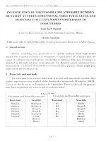
The procedure for fabricating SWCNT microelectrodes is
shown in Fig. 1a. A chromium layer (200 nm) was, firstly, thermally evaporated onto the SWCNT network using the plasma
sputtering method. A photoresist layer with thickness of 15 m
(PMER photoresist) was subsequently spun over the chromium
layer. Disk type patterns of 180 m diameter inside the Pt contacts were formed by exposing to the 458 nm He light for 30 s and
developing in PG-7 solution. The exposed chromium layer was
removed by chromium etchant solution in 2 min. Then a thermal
SiO2 layer of 250 nm was sputtered on exposed SWCNT network by the plasma sputtering method. Finally, the residue disk
89
type of the photoresist layers and chromium layers were clean
by remover and chromium etchant solution, respectively. Note
that between two continuous steps, the SWCNT microelectrodes
were washed by Mili-Q water for 1 min and then blown under
N2 gas to dry. This SWCNT microelectrode is labeled electrode
S.
b) Photoresist layer
The process is depicted in Fig. 1b. According to this way, a photoresist layer of thickness 15 m was directly spun on surface
of SWCNT network via conventional photolithography process.
This layer was then exposed to the 458 nm He light in 30 s with
mask pattern of disk type microelectrode. The diameter of disk
type microelectrode was also 180 m. Finally the photoresist
layer was developed in the PG-7 developing solution and subsequently washed by pure water to get the SWCNT microelectrode.
This SWCNT microelectrode is named electrode P.
In both ways, 24 SWCNT microelectrodes were arrayed on a
single Si substrate of 25 mm × 30 mm.
2.2.4. Measurement
Scanning electron microscopy (SEM) images were obtained
using Hitachi S-4100 with accelerating voltage 20 kV. Raman spectra were performed with laser excitation energy of 514.5 nm on
Micro-Raman machine.
Electrochemical measurements were performed on ALS/CH
Instruments electrochemical analyzer, model 730C (USA) as shown
in Fig. 1c, in which three electrodes system were used with Pt wire
as counter, AgCl/Ag micro-electrode as reference (Microelectrodes
Inc., USA) and SWCNT microelectrodes as working electrode. A drop
of KCl 0.1 M solution (25 l) containing interested electroactive
species was placed in the PDMS chamber over the exposed SWCNT
area.
Cyclic voltammetric measurement on as-grown SWCNT network was conducted by using cone capillary cell, in which the
top and bottom inner diameter of capillary are 3 mm and 0.5 mm,
respectively [19]. The counter and micro-reference electrode were
placed inside the capillary. The approach of capillary to the surface
of SWCNT network was performed by using the manually controlled x-y-z positioner. By this way, the bottom tip of capillary
will not contact with the surface of SWCNT network.
The electrodeposition of Au on SWCNT microelectrodes was
conducted by chronoamperometric technique. The constant potential of −0.4 V versus Ag/AgCl was applied on these microelectrodes
for a period of 20 s in 0.1 M phosphate buffer saline PBS solution
containing 10 mM HAuCl [19].
3. Results and discussion
3.1. Characterization of SWCNT network and microelectrode
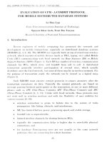
The SEM image of as-grown SWCNT network, shown in Fig. 2a,
clearly illustrates high density of as-grown SWCNT and they exist
in the individual or small bundle tubes. The Raman spectrum of asgrown SWCNT is depicted in Fig. 2b. The shape and position of peaks
in Raman spectrum around 1600 cm−1 (G band) allow to identify
the SWCNT [20]. The characterized peak of disorder graphite at
around 1350 cm−1 (D band) indicates that there is little amorphous
carbon present and that the as-grown SWCNT is high quality, that
there are very few defects in SWCNT [17,18,20].
The distribution of SWCNT diameter can be induced from the
radial breathing mode (RBM) following equation [20].
d=
248
(1)
90
N.X. Viet et al. / Talanta 91 (2012) 88–94
Fig. 1. Schematic of procedure for fabricating SWCNT microelectrodes. (a) Using SiO2 layer as insulator. (b) Using photoresist layer as insulator. (c) The electrochemical
measurement set-up with SWCNT microelectrode as working electrode, Pt wire as counter electrode, and microelectrode Ag/AgCl as reference electrode.
N.X. Viet et al. / Talanta 91 (2012) 88–94
91
Fig. 2. (a and b) SEM image and Raman scattering spectrum of as-grown SWCNT network, respectively.
where is the RBM peak position and d (nm) is the nanotube diameter. From Eq. (1) the nanotube diameter is calculated and given
in the upper x-axis and the value of nanotube diameter is in range
1.0–2.0 nm, in good agreement with those obtained from published
literatures [14,17].
Fig. 3a shows the SEM image of an obtained SWCNT microelectrode. The disk diameter of SWCNT microelectrodes was calculated
from the SEM images and got the value of 185 ± 2.6 m (average of
8 individual samples).
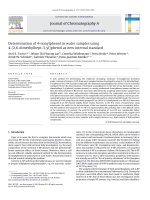
The SEM images of SWCNT network inside electrode S and
electrode P are shown in Fig. 3b and c, respectively. The SWCNT
networks of electrode P after post treatment processes look slightly
thicker than that in as-grown SWCNT network and electrode S as
well. The SEM images exhibit that the density of SWCNT networks
Fig. 3. (a) SEM image of obtained SWCNT microelectrode (b and c) SEM images of SWCNT network inside electrode S and electrode P, respectively.
92
N.X. Viet et al. / Talanta 91 (2012) 88–94
Fig. 4. Cyclic voltammograms in 0.1 M KCl solution containing 0.05 mM K3 [Fe(CN)6 ]/K4 [Fe(CN)6 ] mixture (1:1 molar ratio) of (a) as-grown SWCNT network (b) electrode S
and electrode P. All potential scan rates are 4 mV s−1 .
after post processes seem as high as that of as-grown SWCNT (see
Fig. 2a). This is because the individual or small bundle of SWCNT
entangles each other to increase the stability of network during
post processes. In case of electrode S, the surface of SWCNT network was covered entirely by a sputtering Cr layer. The Cr layer,
however, finally removed by chromium etchant solution, which
specifies to Cr only and does not have any harmful effects to Si
substrate and SWCNT network. This Cr layer also acted as a shield
to prevent direct contact of organic compounds (photoresist, solvents) to the SWCNT network, which is believed strongly effects on
the electrochemical properties of SWCNT [9].
On the other hand, the SiO2 insulator layer is directly applied on
the SWCNT network without the Cr layer. When SiO2 is removed
from SWCNT surface by either wet etching with HF solution [9]
or drying etching [14]. Both etching processes could not exactly
control removing the upper layer of SiO2 insulator. One can lead to
over etching which break the Si substrate destroying the SWCNT
network, another is not completely removed which make SWCNT
network inactive at some areas due to the blocking of SiO2 on the
surface of SWCNT (data not shown).
The SiO2 insulator exhibits some advantages to photoresist insulator [8] including much thermal stable and inert in DMF, DMSO
environment. These solvents are usually used as the solvent for
linker molecular during the immobilization of antibody on the
surface of SWCNT [14,21] in the sensing process compared to photoresist layer.
3.2. Electrochemical properties of the SWCNT microelectrodes
Fig. 4a shows the typical cyclic voltammogram (CV) of as-grown
SWCNT electrode in 0.05 mM K3 [Fe(CN)6 ]/K4 [Fe(CN)6 ] mixture
solution (1:1 molar ratio) at potential scan rate 4 mV s−1 .
The Ep , peak potential separation of forward and backward
curves in a redox couple, is 67 mV suggesting a quasi reversible at
the electrode.
For a microelectrode using SWCNT network, the density/separation of individual or small bundle SWCNT is critical [7].
As observed with the high density SWCNT network, the diffusion
layers of neighbor individual SWCNT likely overlap. As a result, the
CV of this kind of electrodes in measuring the redox species in bulk
solution is similar to a solid planar macroelectrode [22].
The high electroactivity of SWCNT has been recently attributed
by the present of nano-graphitic “impurity” [23,24], which is rich
edge plane material and is the highest electrochemical activity
among carbon materials [25–27], in as-grown SWCNT rather than
by SWCNT itself.
It is clear that the CNT electrode is driving the electron transfer (ET) reaction faster than many other carbon electrodes surfaces
observed [3], with very small apparent activation barrier at the
electrode surface.
On the other hand, the SWCNT microelectrodes show the very
different CV behavior. Fig. 4b shows typical CVs of two different
SWCNT microelectrodes in 0.05 mM K3 [Fe(CN)6 ]/K4 [Fe(CN)6 ] mixture solution, recorded at a potential scan rate of 4 mV s−1 . The CVs
show a well-defined sigmoidal shape, characteristic of steady state
behavior at ultramicroelectrode (UME). The steady state feature
in CV is the strong evidence indicating that most exposed SWCNT
behavior as independent nanoelectrode after post grown processes.
The current magnitude at SWCNT electrode S is much high than
that of electrode P. The current density is induced from CVs to
yield a value of 24.49, and 2.69 A mm−2 for SWCNT electrode S
and P, respectively. This illustrates that the electrode S is much
electrochemical active than electrode P.
There are some possibilities causing this phenomenon (i) the
reduction in density of SWCNT network due to losing of SWCNT
in post grown processes (ii) partial blocking surface of SWCNT
after the contacting of SWCNT with photoresist, which causes the
contamination on SWCNT and (iii) the reduction of nano-graphitic
particles in SWCNT network. For electrode S only the reason i and
iii can affect to the change of CV characterization.
Because the density of SWCNT networks do not change so
much, we tentatively attribute this to the reduction of “impurity”
nano-graphitic particles density in SWCNT after post treatment
processes. In the case of electrode P, the partial blocking surface of
SWCNT by organic compounds from photoresist, which cause the
contamination, also affects strongly on the electrochemical properties [9]. In Fig. 5 shows the SEM images of Au electrodeposited on
electrode S and P. We confirmed that the white spots in the SEM
images are Au by X-ray diffractometry (SEM-EDS) (data not shown).
The density of Au particles on electrode S is clearly higher than that
on electrode P. This is also the evidence that the electrode S is more
active than electrode P.
The current density obtained at electrode S also much high than
that of the MWCNT nanoelectrode array [7], SWCNT UME using
photoresist as insulator layer [8], and micro carbon fiber electrode
[28], 0.4, 2.04 and 9.84 A mm−2 , respectively. The current density
at electrode P is slightly higher than that at the UME, which was
fabricated using similar method [8].
The hysteresis (shift in half wave potential) between the forward
and backward waves indicates a slight departure from a true steady
state response, attributed to the partial overlap of diffusion layers
at some locations in the randomly distributed network [7].
N.X. Viet et al. / Talanta 91 (2012) 88–94
93
Fig. 5. SEM images of Au particles electrodeposited on (a) electrode S (b) electrode P, respectively.
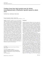
Fig. 6. (a) Cyclic voltammograms of electrode S in 0.1 M KCl solution containing 0.025, 0.05, 0.25, 0.5 and 1.0 mM K3 [Fe(CN)6 ]]/K4 [Fe(CN)6 ] mixture (1:1 molar ratio), scan
rate is 4 mV s−1 . (b) Plot of limiting currents (at 0.4 V) vs. mediator concentration and linear fit for K3 [Fe(CN)6 ].
Fig. 6a shows the CVs of electrode S in the
K3 [Fe(CN)6 ]/K4 [Fe(CN)6 ] mixture solution (1:1 molar ratio) in
the range of 0.025–1 mM with the potential scan rate of 4 mV s−1 .
The diffusion-controlled steady-state limiting current, iss , at a
coplanar disk-shaped microelectrode is given by Eq. (2) [29].
iss = 4nrFDC
(2)
where n is the number of electrons transferred per redox event, F is
the Faraday constant, r is the radius of the disk electrode and C and
D are the bulk concentration and diffusion coefficient of the electroactive species, respectively. The use of Eq. (2) is valid because the
degree to which the electrode is recessed is minimal compared to its
lateral dimension. Fig. 6b shows plot of limiting currents (at 0.4 V)
versus redox species concentration. The linear fit through the points
indicates a near perfect scaling of iss with mediator concentration
(r2 is 0.9903). The diffusion coefficient extracted from the slope of
the plot is 8.8 × 10⁻⁶ cm2 s−1 , which is very good agreement with
literature values [29,30].
The observed plateau in cyclic voltammetric response and the
scaling of iss with concentration of redox mediator in the manner predicted by Eq. (2) indicates that the SWCNT microelectrode
behaves as a conventional metallic UME (e.g., Pt, Au).
4. Conclusion
We have successfully fabricated the SWCNT microelectrodes
based SWCNT network on insulator substrate through microfabrication process. The SWCNT microelectrodes used sputter SiO2
as insulator exhibit some prior advances to these used photoresist
layer as insulator such as much stable in harsh condition (high
active organic solvents) and high current density (24.94 compared
with 2.69 A mm−2 , respectively). These benefits come from using
of Cr layer to cover entirely SWCNT network during the fabricating
processes. In addition, the well-defined geometry of SWCNT microelectrodes is not only useful for investigating kinetics electron
transfer, but also promising candidate in electrochemical sensors
application.
Acknowledgement
This work was partially supported by a Grant-in-Aid for Scientific Research on Priority Areas (No. 19054011) and the Cooperative
Research Program of “Network Joint Research Center for Materials and Devices” from the Ministry of Education, Culture, Sports,
Science and Technology of Japan.
References
[1] S. Iijima, Nature 354 (1991) 56–58.
[2] A.V. Melechko, V.I. Merkulov, T.E. McKnight, M.A. Guillorn, K.L. Klein, D.H.
Lowndes, M.L. Simpson, J. Appl. Phys. 97 (2005) 041301.
[3] R.L. McCreery, Chem. Rev. 108 (2008) 2646–2687.
[4] S. Rosenblatt, Y. Yaish, J. Park, J. Gore, V. Sazonova, P.L. McEuen, Nano Lett. 2
(2002) 869–872.
[5] J. Edgeworth, N. Wilson, J.V. Macpherson, Small 3 (2007) 860–870.
[6] E.S. Snow, P.M. Campbell, M.G. Ancona, J.P. Novak, Appl. Phys. Lett. 86 (2005)
033105.
[7] J. Koehne, J. Li, A.M. Cassell, H. Chen, Q. Ye, H.T. Ng, J. Han, M. Meyyappan, J.
Mater. Chem. 14 (2004) 676–684.
[8] I. Dumitrescu, P.R. Unwin, N.R. Wilson, J.V. Macpherson, Anal. Chem. 80 (2008)
3598–3605.
[9] I. Heller, J. Kong, H.A. Heering, K.A. Williams, S.G. Lemay, C. Dekker, Nano Lett.
5 (2005) 137–142.
[10] D. Wei, M.J.A. Bailey, P. Andrew, T. Ryhanen, Lab Chip 9 (2009) 2123–2131.
[11] H. Luo, Z. Shi, N. Li, Z. Gu, Q. Zhuang, Anal. Chem. 73 (2001) 915–920.
94
N.X. Viet et al. / Talanta 91 (2012) 88–94
[12] C.E. Banks, R.R. Moore, T.J. Davies, R.G. Compton, Chem. Commun. (2004)
1804–1805.
[13] J. Okuno, K. Maehashi, K. Matsumoto, K. Kerman, Y. Takamura, E. Tamiya, Electrochem. Commun. 9 (2007) 13–18.
[14] J. Okuno, K. Maehashi, K. Kerman, Y. Takamura, K. Matsumoto, E. Tamiya,
Biosens. Bioelectron. 22 (2007) 2377–2381.
[15] J.K. Campbell, L. Sun, R.M. Crooks, J. Am. Chem. Soc. 121 (1999) 3779–3780.
[16] J.M. Nugent, K.S.V. Santhanam, A. Rubio, P.M. Ajayan, Nano Lett. 1 (2001)
87–91.
[17] K. Maehashi, Y. Ohno, K. Inoue, K. Matsumoto, Appl. Phys. Lett. 85 (2004) 858.
[18] H.E. Unalan, M. Chhowalla, Nanotechnology 16 (2005) 2153–2163.
[19] P.V. Dudin, P.R. Unwin, J.V. Macpherson, J. Phys. Chem. C 114 (2010)
13241–13248.
[20] M.S. Dresselhaus, G. Dresselhaus, A. Jorio, A.G. Souza Filho, M.A. Pimenta, R.
Saito, Acc. Chem. Res. 35 (2002) 1070–1078.
[21] R.J. Chen, Y. Zhang, D. Wang, H. Dai, J. Am. Chem. Soc. 123 (2001)
3838–3839.
[22] J. Li, A. Cassell, L. Delzeit, J. Han, M. Meyyappan, J. Phys. Chem. B 106 (2002)
9299–9305.
[23] M.E. Itkis, D.E. Perea, R. Jung, S. Niyogi, R.C. Haddon, J. Am. Chem. Soc. 127 (2005)
3439–3448.
[24] P.-X. Hou, C. Liu, H.-M. Cheng, Carbon 46 (2008) 2003–2025.
[25] C.E. Banks, R.G. Compton, Analyst 131 (2006) 15–21.
[26] M. Pumera, Chem. Eur. J. 15 (2009) 4970–4978.
[27] A. Ambrosi, M. Pumera, Chem. Eur. J. 16 (2010) 10946–10949.
[28] Micro carbon fiber electrode (BAS Inc., Japan), diameter: 33 m.
[29] L.R.F. Allen, J. Bard, Electrochemical Methods: Fundamentals and Applications,
2nd ed., 2001.
[30] J.L. Conyers, H.S. White, Anal. Chem. 72 (2000) 4441–4446.