DSpace at VNU: Wedge Mode Propagation Characteristics of Triangular–shaped Surface Plasmon Waveguide
Bạn đang xem bản rút gọn của tài liệu. Xem và tải ngay bản đầy đủ của tài liệu tại đây (665.89 KB, 8 trang )
VNU Journal of Science: Mathematics – Physics, Vol. 32, No. 3 (2016) 41-48
Wedge Mode Propagation Characteristics
of Triangular–shaped Surface Plasmon Waveguide
Nguyen Van Chinh, Nguyen Thanh Huong, Chu Manh Hoang *
International Training Institute for Materials Science, Hanoi University of Sciences and Technology,
No.1, Dai Co Viet, Hai Ba Trung, Hanoi, Vietnam
Received 15 September 2016
Revised 28 September 2016; Accepted 30 September 2016
Abstract: In this paper, we investigate wedge mode propagation characteristics of a triangularshaped surface plasmon waveguide. This structure consists of a thin metal layer deposited onto the
surface of a triangular–shaped silicon waveguide which could be fabricated on a silicon–on–
insulator wafer by wet–bulk micromachining. These elements are embedded in a dielectric
medium (such as air) to form metal–dielectric interface and the surface plasmon wave propagates
at the wedge of metal layer. The influence of structural parameters such as metal layer, height of
silicon waveguide and effect of fabrication on the wedge mode propagation characteristics of the
waveguide is analyzed by using numerical simulation.
Keywords: V–shaped waveguide, Surface plasmon polariton, plasmonic waveguide.
1. Introduction
Surface Plasmon Polariton (SPP) is surface electromagnetic wave which propagates at the metal–
dielectric interface. It is the result of the strong coupling between light and collective oscillation of
free electron at a metal surface. In recent decades, the study on the theories and applications of SPP is
growing fast and separated in a new field – Plasmonics. As a surface wave, the propagation of SPP is
highly sensitive to the roughness and the electromagnetic field is confined in the space near the
interface of the medium. There are many studies on novel devices to apply the sensitivity of SPP for
biosensors [1–3]. In these structures, the interaction of biological reagents will change the surface
properties of devices. Therefore, the propagation characteristics of SPP will be changed. One of other
valuable properties of SPP, which makes it so interesting, is the confinement of wave in nano–scale.
To achieve photonic circuits with high integration density, it is necessary to reduce the size of
elements such as structures to guide optical signal. Three kinds of typical nanophotonic waveguides
have been developed, which includes nanophotonic wires [4, 5], photonic-crystal waveguides [6] and
nanoplasmonic waveguides [7]. The former two nanophotonic waveguides, which utilize nanostructures with ultra-high index contrast, are limited due to the classical optical diffraction phenomena.
In contrast, a nanoplasmonic waveguide can break the diffraction limit and enable deep sub-
_______
Corresponding author. Tel.: 84-4-38680787
Email:
41
42
N.V. Chinh et al. / VNU Journal of Science: Mathematics – Physics, Vol. 32, No. 3 (2016) 41-48
wavelength confinement and wave-guiding of light, which makes it become a very attractive candidate
for ultra-high integration density. Numerous of nanoplasmonic waveguides have been proposed and
demonstrated in past years, including metal nano-slot waveguides [8], strip waveguides [9], metal Vgroove waveguides [10], wedge waveguides [5], and hybrid waveguides [11][12]. Among these, the
wedge plasmon polariton (WPP) waveguides are the most prominent about the possibility of
electromagnetic field confinement. In this paper, we will study about a WPP waveguide that can be
fabricated by wet – bulk micromachining.
2. Model of the surface plasmon polariton waveguide
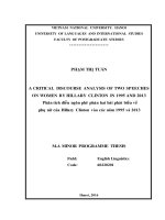
Structure of surface plasmon polariton waveguide is shown in Fig. 1. This structure consists of a
triangular silicon waveguide, which is fabricated on a Silicon–on–Insulator (SOI) wafer. A noble
metal layer is deposited onto the surface of the waveguide to form metal–dielectric interface. The
silicon waveguide forms a mold to deposit a metal layer in an inverted V-like shape. The interface
between the V-shaped metal layer and air medium is used for guiding surface plasmon wave. The
surface plasmon polariton (WPP) mode propagates on the top wedge of structure. We will evaluate the
dependence of propagation characteristics on the change of structural parameters such as deposited
metal layer and dimensions of silicon waveguide.
Fig 1. Schematic of triangular-shaped plasmonic waveguide used for simulation: (a) a 3D view of the waveguide
and (b) cross-section of the waveguide.
The Maxwell theory describes the expression of SPPs wave on a metal–dielectric interface by [13]
(1)
with the effective refractive index and skin depth
(2)
(3)
Using parameters in Table 1, we obtain the effective refractive index and mode size of SPPs
propagating along the silver–air interface being 1.0038 and 2.86 µm, respectively.
N.V. Chinh et al. / VNU Journal of Science: Mathematics – Physics, Vol. 32, No. 3 (2016) 41-48
43
On a metal tip, WPP is the coupling mode formed by two SPP waves propagating toward the tip
on the two opposite faces of the wedge [14]. These SPPs stop at the tip of wedge with both their phase
and group velocities. The group velocity tends to zero and the wave vector tends to infinite at the tip.
This leads to infinitesimal mode size (nanofocusing) and the wave can be propagated on very large
distance. However, this model is applied only to very small wedge angle (7o). For the large wedge
angle (70.6o), we must use numerical simulation methods to solve.
Table 1. Parameters used for simulating SPP mode
Symbol
Value
Difination
λ
1.55 µm
Wavelength in vacuum
l
10 µm
Length of waveguide
h
1 µm
Height of waveguide
nSi
3.4757
Refractive index of silicon
nSiO2
1.4957
Refractive index of silicon dioxide layer
nAg
0.15649 – 11.567i Complex refractive index of Silver
nAu
0.23823 – 11.263i Complex refractive index of Gold
α
54.7o
Sidewall angle
t
(10:10:200) nm
Thickness of metal layer
By finite element method, we can find the propagation constant of WPP mode, that satisfies
eigenvalue equations
(∇ - ik1) × ((∇ - ik1) × E1) – ko2εrE1 = 0
(4)
2
(∇ - ik2) × ((∇ - ik2) × E2) – ko εrE2 = 0
(5)
In our study, we used software COMSOL, a commercial product for academic purpose to solve
these equations. The model is three – dimension with the calculation size is 4x4x10 µm3. Two
boundary ports are applied on the back and front face of the waveguide to analyze modes that can
propagate in structure. The perfectly matched layer is larger than five times the calculation domain and
the minimum mesh size is about 1 nanometer (at near the wedge of waveguide).
3. Results and discussion
Firstly, we investigate the influence of metal layer on the propagation of plasmon wave on the
waveguide. In this study, we use two metals being gold and silver, which are common in plasmonic
technology, to simulate. The metal layer can be deposited onto triangular silicon waveguide by
sputtering technique. The thickness is studied in each step of 10 nm in the range from 10nm to 200
nm. To ensure that the thickness of metal film is the same throughout the structure, the wedge of metal
is filleted with a radius equal to the thickness of the metal layer.
44
N.V. Chinh et al. / VNU Journal of Science: Mathematics – Physics, Vol. 32, No. 3 (2016) 41-48
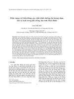
Fig 2. Distribution of normalized electric field in the cross-section of waveguide at various thicknesses of
silver and gold layer: (a)-(b) for Ag with the thicknesses of 10 nm and 200nm respectively and (c)-(d) for Au
with the thicknesses of 10 nm and 200nm respectively; (e) Distribution of normalized Electric field in air along
the (BB’) cutline as shown in Fig. 1 (b).
Figure 2 (a)-(d) shows the distributions of electric field that are normalized with respect to
maximum field value. For both metals, the maximum electric field values are almost the same. When
the thickness of metal layer increases, the maximum electric field values also increase. The electric
field distributes in air medium, and concentrates mainly on the area round the wedge of the
waveguide. This electric field reaches the maximum value at metal surface and declines rapidly when
it is away from the surface. Figure 2 (e) describes more clearly about the sharp decline of the field
along (BB’) cutline (shown in Fig. 1). The field falls off exponentially in air, the intersection of these
curves with 1/e line giving a quantitative estimation of the confinement of electromagnetic energy. As
seen in Fig. 2 (e), the mode size is almost constant for two metals. In the case of very thin metal layer
(10nm), the field falls off to 1/e at a distance of only a few tens of nanometers. Otherwise, in the case
of thick metal film (200nm), the mode size increases to about 500 nm. Thus, the confinement of
waveguide mode does not depend on the nature of metal, but depends strongly on the thickness of
metal layer.
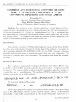
The propagation characteristics of the waveguide at various metal thicknesses are shown in Fig. 3.
Here, we evaluate three feature parameters being effective mode index neff (the ratio of wave number
of WPP mode and wave number in vacuum), propagation length (the distance at which the field
intensity decreases e time) and mode area (area bounded by a curve where electric field falls off to 1/e)
(Figs. 3 (a)-(c)). Figure 3 (d) shows the shape of mode area (the red area at the wedge of waveguide).
When the metal thickness increases, the effective mode index decreases and the propagation length
increases. Both these quantities tend asymptotically to a value corresponding to the infinite thickness.
The mode area of gold and silver are almost the same and increase strongly with the thickness. With
the same structural parameters, the attenuation using gold is stronger than using silver about two
times, while other characteristics are almost the same. So, we choose silver for forming the metaldielectric interface for the following study.
As seen in Fig. 3 (b), at the thickness t = 20 nm, the propagation length has a minimum value. It
might be due to the coupling of WPP with a high order mode in silicon waveguide. Increasing the
thickness of metal layer, the coupling decreases and will be negligible at thickness larger than 150nm.
N.V. Chinh et al. / VNU Journal of Science: Mathematics – Physics, Vol. 32, No. 3 (2016) 41-48
45
Fig 3. Propagation characteristics of WPP mode at various thicknesses of metal (a)-(c)
and the shape of mode area (d).
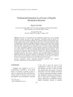
Fig 4. (a)-(c) are distributions of electric field, when we fillet the top corner of silicon waveguide; (d)-(f) are
propagation chracteristics of waveguide at various thicknesses of metal, in which R = t (blue line) and R = 200
nm (red line) are for the plasmonic waveguide with and without the silicon waveguide filleted at the top wedge
corner, respectively.
46
N.V. Chinh et al. / VNU Journal of Science: Mathematics – Physics, Vol. 32, No. 3 (2016) 41-48
In the above study, we have filleted the wedge of metal layer with radius equal the value of metal
thickness. It leads to the changing of wedge mode area that concentrates the electromagnetic energy,
thus the propagation of WPP mode is changed. To keep the wedge radius of metal constant, we have
to fillet the top wedge corner of silicon waveguide with the appropriate value of radius. Figure 4
shows the simulation results with the radius of metal wedge is always 200nm. For the homogenization
of metal layer on the entire structure, we set the filleted radius of silicon waveguide is (200 – t) nm
with respective to the thickness of metal layer t. Figures 4 (a)-(c) displays the distribution of
electromagnetic field with three metal thicknesses, t = 10 nm, 60 nm, and 200nm, respectively. If we
increase the thickness of metal, the maximum value of field will be increased, which is the same as the
wedge of silicon waveguide not filled. However, the propagation properties in this case are slightly
different (Figs.4 (d)-(f)). For comparison, the propagation mode characteristics of the silicon
waveguide without filleting the top wedge corner are also shown in Figs. 4 (d)-(f). The propagation
length is no longer a minimum value at 20nm and reaches a maximum value at
Fig 5. Electromagnetic field of WPP mode distributes on the wedge of waveguide at different heights in two
cases t = 60nm (a)-(c) and 200nm (d)-(f).
the thickness of 60nm. With the same thickness, the attenuation in structure with the filleted top
wedge corner of silicon waveguide is smaller than in the remaining structure. It may be due to the
decreasing of confinement of WPP mode. This investigation on the filleting effect is a guideline for
predicting the operation characteristics of the waveguide when there is variation in fabrication condition.
The dependence of WPP mode on the height h of triangular cross–section of the waveguide is
studied in next section. In the fabrication using wet–bulk micromachining on SOI wafer, the height of
waveguide approximates the thickness of device layer. So, by choosing SOI wafers having different
device layer thicknesses, we can change the height of the waveguide. The parameters used for
simulation are taken from Table 1 while h is varied from 0.5μm to 5µm. Figure 5 displays the
distribution of electromagnetic field at various values of h in which the thicknesses of metal layer are
60nm for Figs. (a)-(c) and 200nm for Figs. (d)-(f). In waveguides with large height (h = 5μm),
electromagnetic field concentrates mainly on the wedge of the waveguide. In waveguides with low height
(h ≤ 0.5μm), the field not only distributes on the wedge but also spreads over the surface of substrate.
N.V. Chinh et al. / VNU Journal of Science: Mathematics – Physics, Vol. 32, No. 3 (2016) 41-48
47
Fig 6. The propagation characteristics of waveguide are investigated as a function of h
when t = 60nm (red line) and 200nm (blue line).
The propagation characteristics depending on the height of the waveguide are shown in Fig. 6. In
the case of large metal thickness, when the height increases, the wavenumber (neff) and the attenuation
(1/Lwpp) increase and they approach to special values when h is more than 2μm. In the case that the
thickness is 60nm, the coupling with high order mode in the silicon waveguide makes the curve
fluctuate, but the shape is the same. Approximately, we can explain that phenomena as follow: the
WPP mode is the result of coupling between two SPPs waves that propagate on two sidewalls of the
waveguide. This coupling is like the coupling in a thin metal film with the variation of thickness. It
makes wavenumber increase, but exchanged by the increase of loss. When the height is more than
2μm, the film becomes so thick that the coupling is negligible and only the part nears the wedge
contributing to the coupling. This causes the saturation of wavenumber and propagation length of
WPP mode in the waveguide. When h is too small, the coupling becomes weak and the effective mode
index of WPP mode approximates the mode index of SPPs (nspp = 1.0038).
4. Conclusion
We have investigated in detail propagation characteristics of the wedge surface plasmon
waveguide depending on geometrical parameters and deposited metal. The investigated results show
that the mode confinement and propagation length strongly depend on the thickness of metal layer.
The mode confinement decreases when the thickness of metal layer increases. When the height of the
waveguide increases, the mode size and propagation length decrease.
Acknowledgments
This research is funded by Vietnam National Foundation for Science and Technology
Development (NAFOSTED) under grant number “103.02-2015.86”.
References
[1] Brolo, A.: Plasmonics for future biosensors. Nat. Photonics. 6, 709–713 (2012).
[2] Gao, Y., Gan, Q., Xin, Z., Cheng, X., Bartoli, F.J.: Plasmonic Mach-Zehnder interferometer for ultrasensitive onchip biosensing. ACS Nano. 5, 9836–9844 (2011).
48
N.V. Chinh et al. / VNU Journal of Science: Mathematics – Physics, Vol. 32, No. 3 (2016) 41-48
[3] Rodrigo, D., Limaj, O., Janner, D., Etezadi, D., Abajo, F.J.G. De, Pruneri, V., Altug, H.: Mid-infrared plasmonic
biosensing with graphene. Science, 349, 165–168 (2015).
[4] Han, Z., Bozhevolnyi, S.I.: Radiation guiding with surface plasmon polaritons. Rep. Prog. Phys. 76, 16402
(2013).
[5] Moreno, E., Rodrigo, S.G., Bozhevolnyi, S.I., Martín-Moreno, L., García-Vidal, F.J.: Guiding and focusing of
electromagnetic fields with wedge plasmon polaritons. Phys. Rev. Lett. 100, 1–4 (2008).
[6] Pile, D.F.P., Ogawa, T., Gramotnev, D.K., Okamoto, T., Haraguchi, M., Fukui, M., Matsuo, S.: Theoretical and
experimental investigation of strongly localized plasmons on triangular metal wedges for subwavelength
waveguiding. Appl. Phys. Lett. 87, 1–4 (2005).
[7] Bian, Y., Gong, Q.: Deep-subwavelength light confinement and transport in hybrid dielectric-loaded metal
wedges. Laser Photonics Rev. 8, 549–561 (2014).
[8] Dionne, J.A., Sweatlock, L.A., Atwater, H.A., Polman, A.: Plasmon slot waveguides: Towards chip-scale
propagation with subwavelength-scale localization. Phys. Rev. B - Condens. Matter Mater. Phys. 73, 1–9 (2006).
[9] Gao, L., Tang, L., Hu, F., Guo, R., Wang, X., Zhou, Z.: Active metal strip hybrid plasmonic waveguide with low
critical material gain. Opt. Express. 20, 11487 (2012).
[10] Dintinger, J., Martin, O.J.F.: Channel and wedge plasmon modes of metallic V-grooves with finite metal
thickness. Opt. Express. 17, 2364–2374 (2009).
[11] Bian, Y., Gong, Q.: Low-loss hybrid plasmonic modes guided by metal-coated dielectric wedges for
subwavelength light confinement. Appl. Opt. 52, 5733–41 (2013).
[12] Gui, C., Wang, J.: Wedge hybrid plasmonic THz waveguide with long propagation length and ultra-small deepsubwavelength mode area. Sci. Rep. 5, 11457 (2015).
[13] Raether, H.: Surface plasmons on smooth and rough surfaces and on gratings, Springer Tracts in Modern Physics,
Vol. 111. (1988).
[14] Gramotnev, D.K., Vernon, K.C.: Adiabatic nano-focusing of plasmons by sharp metallic wedges. Appl. Phys. B
Lasers Opt. 86, 7–17 (2007).