DSpace at VNU: The Gamma Ray Transmission Factor of Spent Fuel
Bạn đang xem bản rút gọn của tài liệu. Xem và tải ngay bản đầy đủ của tài liệu tại đây (244.56 KB, 5 trang )
VNU Journal of Science: Mathematics – Physics, Vol. 32, No. 4 (2016) 52-56
The Gamma Ray Transmission Factor of Spent Fuel
Nguyen Van Quan1,*, Bui Van Loat1, Nguyen Cong Tam2
1
VNU University of Science, 334 Nguyen Trai, Hanoi, Vietnam
Center of Energy Research, Hungarian Academy of Sciences
2
Received 16 November 2016
Revised 8 December 2016; Accepted 28 December 2016
Abtract: Passive non-destructive methodswere developed for determining total U, 235U and total
Pu content of damaged spent fuel. The methods based on correlations between 137Cs and U, Pu
content and using referent spent fuel assemblies. It means that the nuclear material content can be
derived from measurable137Cs content, which depends on gamma ray transmission factor. In this
work, this factor was determinedby aninfinite energy method and the same for both damaged and
referentspent fuel with error less than 12%.
Keywords: Passive non-destructive methods, Damaged spent fuel,Referentspent fuel,Transmission
factor, Infinite energy method.
1. Introduction
On the Unit 2 at Paks Nuclear Power Plant accident occurred on 2003 [1]. Due to the accident
thirty fuel assemblies damaged in the cleaning tank and casing of the fuel elements and uraniumdioxide pellets in them damaged. All of them were mainly in 72 canisters containing broken fuel rods
as well as pellets and parts of cladding. The canisters have two types: T28 contained materials of one
or two damaged spent fuel assemblies (in separated volume) and type T29 contained an
inhomogeneous mixture of spent fuel pieces of different burn-up distributed in an irregular geometry
[1]. Especially, K types, is the spent fuel, which didn’t damaged and used as referent sample.
Theexperimentalmethod todetermine U and Pu content need to know 137Cs and 134Cs contents
(activity), whichareinversely proportional to transmission factor.
The activity of 134Cs can be calculated by:
A(134Cs )
CE
1
*
E .BrE FE
(1)
where
- E is the energy of gammaray.
_______
Corresponding author. Tel.: 84-982566558
Email:
52
N.V. Quan et al. / VNU Journal of Science: Mathematics – Physics, Vol. 32, No. 4 (2016) 52-56
53
- C E , E , BrE are respectively countrate, absolute detectionefficiency, and branching ratio of
gamma ray at energy E.
- FEis transmission factor of spent fuel at energy E.
2. Method fordetermination of the gamma ray transmission factorFE.
2.1. The transmission factor of cylindrical sample
From the fundamental law of gamma ray attenuation, the transmission factor of gamma rays
through a uniform slab sample is FE exp l x . Where l isthe linear attenuation coefficient, x is
the thickness of the sample. In fact, itisimpossible to formulate FE for the complex shape samples.
For a cylindrical sample viewed along a diameter in the far field, the transmission factor can be
determined by the following formulas, [2]:
CF ( AT )
CF ( AT )
ln FE
1 FE
(2)
l R
I1 l R L1 l R
(3)
where CF(AT) is a correction factor for self-attenuation in the sample, FE is transmission factor,R
is sample radius, L1 is modified Struve function of order 1, and I1 is modified Bessel function of order 1.
These expressionsare very compact, but it is inconvenient to use because of Struve and Bessel
functions [3]. Hence, the infinite energy method constructed from 6 gamma rays of 134Cs has been
used for determining the value of the transmission factorFE.
2.2. Determination of FE by infinite energy method
Because ofself-absorption in sample depend on a number of factors, including spentfuel
composition, density, dimensions and gamma-ray energy [4]. Hence, the transmission factor was too
difficult to be obtained directly from the formulas (2) and (3). In this case,the infinite energy method
was considered to determine this factor.The method supposes that all gamma rays would through the
fuel at infinite energy or F∞= 1 and the logarithm of thecount rate over branching ratio is linearly
related with 1/E, which can be presented by the following:
C
ln E
BrE
a
b
E
a
C E C E (0) exp
E
(4)
(5)
wherea, b are respectively the fitting parameters, CE (0) is thetrue count rates if neglecting gamma
ray self-absorption of fuel.
Finally, the transmission factor of spent fuel can be expressed by:
a
FE exp
E
(6)
54
N.V. Quan et al. / VNU Journal of Science: Mathematics – Physics, Vol. 32, No. 4 (2016) 52-56
3. Results and discussion
The gamma spectra of T28, T29 and referent (K) spent fuel samples can be obtained by using the
scanning method with high resolution gamma spectrometer. The HPGe detector was placed behind the
collimator built into the concrete wall of the service pit of the reactor block. The investigated canister
was moved up and down under water in the service pit in front of the collimator, by the refueling
machine. The width of the collimator opening was ~20 cm, while its height was ~1 cm, making it
possible to collect gamma spectrometric information with a relatively high spatial precision. Canisters
were scanned in both directions (up and down) from 3 sides, which ensure the cancellation of the
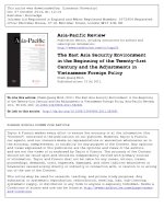
geometric effects due to asymmetric positioning [1].Fig.1 shown the gamma spectra of referent spent
fuel, K56491, which was obtained from the measurement.
Fig.1. The typical gamma spectra of spent fuel (K56491).
As mentioned before, the gamma rays of 134Cs were used to calculate the energy dependent
transmission factor FE. The information about energy and also branching ratios of them are presented
in Table 1.
Table 1. Characteristics of gamma rays used for calculation [5]
Isotopes
134
137
Cs
Cs
Energy, keV
Branching ratio, %
569.29
15.43
604.66
97.60
795.76
85.40
801.84
8.73
1167.86
1.80
1365.13
3.04
661.62
84.62
N.V. Quan et al. / VNU Journal of Science: Mathematics – Physics, Vol. 32, No. 4 (2016) 52-56
55
Analyzing the gamma spectra by GammaVision Ver5.1, net and background countsof gamma
peaks for each spent fuel type can be obtained easily (Table 2). Using the values of the count, live
time, branching ratio and energy of gamma rays of 134Cs, the logarithm of count rates over branching
ratios for the spent fuel types T28, T29, and Referent (K) are shown in figure 2.
Table 2. Measured data of the gamma spectra of K56491, T28 and T29 samples
Isotopes
134
137
Cs
Cs
Live Time
Energy,
keV
K56491
T28
T29
Net
counts
Background
Net
counts
Background
Net
counts
Background
569.29
29267
123520
3264
21300
2056
16117
604.66
206694
127950
22247
17927
15699
14764
795.76
306452
29619
32474
6048
22502
4504
801.84
31610
24302
3464
5164
2165
4407
1167.86
11803
8338
1191
2666
775
1878
1365.13
24203
5865
2708
2112
1808
1681
661.62
310196
58846
127073
19287
63182
11734
5213.8 sec
7932.78 sec
8784.54 sec
First, by using the data from table 1, 2 and linear fitting function, the fitting parameters a, b can be
taken easily. Finally, the transmission factor of 661.62 keV gamma ray of 137Cscan be found by using
the formula (6).From Fig. 2,it can be seen that all three curves seem to be parallel. i.e., the values of a
in equation (4) are the same. It means that the transmission factor formula would be the one for all
three spent fuel types.The obtained results and uncertainties are presented in Table 3.
Fig.2. The typical count rates/branching ratios of gamma rays from 134Cs versus 1/E of T-28 (red), T-29 (blue)
C
1407
and Ref (dark) samples.The fitting results of K, T28 and T29 are ln E
6.032 , R2 =
E
BrE
C
1379
C
1375
2
0.997; ln E
3.351 , R2 = 0.991; and ln E
2.830 , R = 0.987, respectively.
Br
E
E
BrE
E
N.V. Quan et al. / VNU Journal of Science: Mathematics – Physics, Vol. 32, No. 4 (2016) 52-56
56
To evaluate uncertainty of the transmission factor,equation (6) and the error propagation formula
were used:
F
F
E a2 E E2 FE a
E
a
E
2
F
2
(7)
where F , a , E respectively represents the standard deviation of F, a, and E.
Table 3. The present results of the transmission factor of 661.62 keV from 137Cs for different samples
Label
a
b
FE
Uncertainty (%)
K56491
1407.0 ± 35.7
6.032 ± 0.014
0.1167 ± 0.0630
5.4
T28-020
1379.0 ± 65.4
3.351 ± 0.026
0.1244 ± 0.0123
9.9
T29-025
1375.0 ± 77.9
2.830 ± 0.030
0.1252 ± 0.1477
11.8
4. Conclusion
The determination of the transmission factor of spent fuel by correction factor of gamma ray selfattenuation and infinite energy method was presented. The infinite energy method wasdeveloped and
used to determine transmission factor FE of three spent fuel types. The obtained results of the factor
for T28, T29 and K are respectively 0.1167 ± 0.063,0.1244± 0.0123, and 0.1252± 0.1477. The
uncertainty of the present results issmaller than 12%. In addition, the results show that the
transmission factors of 661.62 keV are almost the same for all three spent fuel types. It indicates that
the referent spent fuel can be used to evaluate 137Cs content of the damaged fuel.
References
[1] Nguyen C. T., Almasi I., Lakosi L., Zsigrai J., Buglyó N., Pásztor Cs., and BeierM,Non-destructive measurement
of U and Pu content of inhomogeneous items originating from spent fuel, IAEA-CN-184/252.
[2] D. Reilly, N. Ensslin, and H. Smith, Jr., “Passive Nondestructive Assay of Nuclear Materials”, LA-UR-90732,167-170 (1991)
[3] Milton Abramowhz and Irene A. Stegun, “Handbook of Mathematical Functions with Formulas, Graphs, and
Mathematical Tables”, Applied Mathematics Series 55 (1970).
[4] McMahon CA, Fegan MF, Wong J, Long SC, Ryan TP, and Colgan PA, Determination of self-absorption
corrections for gamma analysis of environmental samples: comparing gamma-absorption curves and spiked
matrix-matched samples, Appl. Radiat. Isot.60, 571-577, (2004).
[5] S.Y.F. Chu, L.P. Ekström, and R.B. Firestone, “The Lund/LBNL Nuclear Data Search”, (1999).