DSpace at VNU: Energy-Efficient Cooperative Techniques for Infrastructure-to-Vehicle Communications
Bạn đang xem bản rút gọn của tài liệu. Xem và tải ngay bản đầy đủ của tài liệu tại đây (1.28 MB, 10 trang )
IEEE TRANSACTIONS ON INTELLIGENT TRANSPORTATION SYSTEMS, VOL. 12, NO. 3, SEPTEMBER 2011
659
Energy-Efficient Cooperative Techniques for
Infrastructure-to-Vehicle Communications
Tuan-Duc Nguyen, Olivier Berder, and Olivier Sentieys, Member, IEEE
Abstract—In wireless distributed networks, cooperative relay
and cooperative multiple-input–multiple-output (MIMO) techniques can be used to exploit the spatial and temporal diversity
gains to increase the performance or reduce the transmission
energy consumption. The energy efficiency of cooperative MIMO
and relay techniques is then very useful for the infrastructureto-vehicle (I2V) and infrastructure-to-infrastructure (I2I) communications in intelligent transport system (ITS) networks, where
the energy consumption of wireless nodes embedded on road
infrastructure is constrained. In this paper, applications of cooperation between nodes to ITS networks are proposed, and the
performance and the energy consumption of cooperative relay
and cooperative MIMO are investigated and compared with the
traditional multihop technique. The comparison between these
cooperative techniques helps us choose the optimal cooperative
strategy in terms of energy consumption for energy-constrained
road infrastructure networks in ITS applications.
Index Terms—Cooperative multiple-input–multiple-output
(MIMO), distributed space-time coding, energy efficiency,
infrastructure-to-vehicle
communications,
wireless
communications.
I. I NTRODUCTION
I
N future intelligent transport systems (ITS), information and
communication from the road infrastructure to vehicle (I2V)
will play a key role in driving assistance, floating car data, and
traffic management to make the road safer and more intelligent.
The communications are supported by wireless nodes that are
integrated in road signs (or traffic infrastructure along the road)
and vehicles. Although wireless nodes that are embedded in
vehicles can take profit from their battery or can regularly be
recharged, each road sign wireless node is usually powered by
a small battery that may not be rechargeable or renewable for
a long time (or powered by a low power solar battery). Even
if such networks are mainly concentrated in cities (but new
applications also appear for rural junctions), many of the nodes
are not necessarily connected to an electrical power supply
due to the civil engineering cost. The energy consumption of
road infrastructure wireless nodes is, consequently, one of the
Manuscript received August 15, 2009; revised September 13, 2010; accepted
February 7, 2011. Date of publication March 17, 2011; date of current version
September 6, 2011. The Associate Editor for this paper was S. Ukkusuri.
T.-D. Nguyen is with the School of Electrical Engineering, Ho Chi Minh
City International University, Vietnam National University, Ho Chi Minh City
70000, Vietnam (e-mail: ).
O. Berder and O. Sentieys are with the Institut de Recherche en Informatique
et Systèmes Aléatoires (IRISA), University of Rennes 1, 35042 Rennes Cedex,
France (e-mail: ; ).
Color versions of one or more of the figures in this paper are available online
at .
Digital Object Identifier 10.1109/TITS.2011.2118754
important constraints when increasing the reliability and the
lifetime of this network.
As the transmission power quickly increases as a K power
function of the transmission distance (with typical path loss
factor 2 < K < 6), the transmission energy consumption plays
an important role for medium- and long-range transmission
and represents the dominant part of the total energy consumption. In some ITS applications, energy-efficient transmission techniques are very important for the communication
from an energy-constrained device such as road I2V or to
another energy-constrained device [road infrastructure to road
infrastructure (I2I)]. In the traditional approach, the multihop
transmission technique is used to reduce the transmission energy consumption by dividing the long transmission channel
into multiple short transmissions.
The cooperative relay technique can exploit the spatial and
temporal diversity gains to reduce the path loss effect in wireless channels. The result is that the system performance is
improved or less energy is needed for data transmission. Relay
techniques are recognized as a simple energy-efficient way of
extending the transmission range due to their simplicity and
their performance for wireless transmissions over fading channels [1]–[3]. These techniques have recently been studied in the
context of vehicle-to-vehicle (V2V) communications in [4].
Aside from the relay technique, some individual sensor
nodes can cooperate at the transmission and the reception to
deploy a cooperative multiple-input–multiple-output (MIMO)
transmission scheme [5]–[7]. Classical MIMO transmission is
investigated for V2V transmissions and should be proposed in
the future IEEE 802.11.p standard. Unfortunately, nodes that
are embedded in the road signs cannot have more than one
antenna because of the limitations in space, cost, and energy
consumption. Therefore, classical MIMO cannot be applied to
I2I and I2V communications. On the other hand, cooperative
MIMO can exploit the diversity gain of the space–time coding
technique to increase the system performance or to reduce the
energy consumption. In [8] and [9], it has been shown that
cooperative multiple-input–single-output (MISO) and MIMO
systems are more energy efficient than single-input–singleoutput (SISO) and traditional multihop SISO systems for
medium- and long-range transmission in wireless distributed
sensor networks. Other recent works on MIMO space–time
block code (STBC) transmission in ITS applications can be
found in [10] and [11]. One the other hand, cooperation between nodes can also help extend the transmission range (with
the same output power of one wireless node), thus increasing
the communication distance between two nodes or two groups
of nodes.
1524-9050/$26.00 © 2011 IEEE
660
IEEE TRANSACTIONS ON INTELLIGENT TRANSPORTATION SYSTEMS, VOL. 12, NO. 3, SEPTEMBER 2011
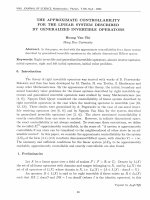
Fig. 1. I2I and I2V wireless communications in the CAPTIV Project.
In this paper, these cooperative techniques are adopted to
ITS applications and characterized for I2V and I2I cooperative
transmissions. The context of this paper is the Cooperative
Strategies for Low-Power Wireless Transmissions Between
Infrastructure and Vehicles (CAPTIV) Project [12], where a
network composed of wireless nodes at a junction has to give
arriving vehicles short-term information for driving assistance
and long-term information for traffic management. It is shown
that the cooperative MIMO and relay techniques are better than
the SISO and multihop SISO techniques in terms of performance and energy consumption. Both techniques are interesting
in the energy-constrained ITS applications, and the advantages
of each technique depend on the particular network structure
or on the application. Based on a reference model, energy consumption calculations help us choose the optimal cooperative
strategy in terms of energy consumption for CAPTIV with
respect to the transmission distances between two junctions or
between a junction and a vehicle.
The rest of this paper is organized as follows. The principle of
cooperative strategies for the energy consumption optimization
are presented in Section II. In Section III, the energy calculation
model is proposed, and simulation results on the energy consumption comparison of cooperative techniques in CAPTIV are
presented. Finally, conclusions and discussions are contained in
Section IV.
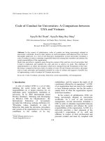
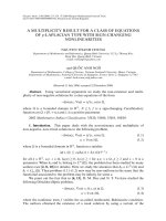
Fig. 2.
Three-terminal relay diversity scheme.
road) and arriving vehicle indications (e.g., to help a driver at a
stop whether to start on the main road in case of smog, heavy
rain, or snow). In such a network, every kind of information
can be transmitted, leading to more advanced applications that
integrate live data and feedback from a number of other sources,
e.g., parking guidance and information systems, and weather
information.
In the CAPTIV system, information is transmitted due to
vehicles and existing infrastructure within a network whose
typical size is metropolitan. The communications can occur
from I2V, I2I, a vehicle to road infrastructure (V2I), or from
one vehicle to another vehicle (V2V). The energy constraint for
road sign infrastructure is very important, because batteries in
traffic road signs cannot be replaced for a long time.
A. Relay and Cooperative MIMO Techniques
II. C OOPERATIVE T RANSMISSIONS AND C OOPERATIVE
S TRATEGIES FOR L OW-P OWER W IRELESS T RANSMISSIONS
B ETWEEN I NFRASTRUCTURE AND V EHICLES C ONTEXT
A scientific coordination group devoted to intelligent transportation systems (ITSs), called Groupement d’Intérêt Scientifique (GIS) ITS Bretagne, has been set up in the Brittany
region of France to investigate this research area. One of its
projects, i.e., CAPTIV, aims at using existing infrastructure,
i.e., not only road signs but also every infrastructure along
the road, to transmit information inside a wireless network,
including equipped vehicles, as illustrated in Fig. 1. The first
applications offered by CAPTIV are road signs anticipated displays (including dynamic situations as temporary works on the
The traditional model for the relay diversity technique with
one relay node, as shown in Fig. 2, consists of a source
node S, a destination node D, and a relay node R. The relay
transmission from S to D can be performed by a two-time slot
transmission. In the first time slot, signals are transmitted by the
source S to the destination node D and the relay node R at the
same time. In the second time slot, the relay node retransmits
the information previously received. At node D, the receiver
combines received signals by using a diversity combination
technique, e.g., maximum-ratio combination (MRC) or equalgain combination (EGC), before symbol detection.
In relay cooperative networks, the received signal comes
from different independent fading channels so that the
NGUYEN et al.: ENERGY-EFFICIENT COOPERATIVE TECHNIQUES FOR I2V COMMUNICATIONS
661
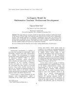
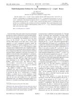
Fig. 3. Cooperative MIMO transmission scheme from S to D with N cooperative transmission nodes (S, CT,1 , CT,2 , . . . , CT,N −1 ) and M cooperative
reception nodes (D, CR,1 , CR,2 , . . . , CR,M −1 ).
probability of deep fading is minimized. This diversity gain
helps decrease the error rate or the transmission power for the
same required error rate. Relay techniques can be classified
according to their forwarding strategy. There are three main
methods for the relay node to transmit the received frame to
the destination node: 1) amplify and forward; 2) decode and
forward; and 3) re-encode and forward.
The MIMO technique can exploit the diversity gain of the
space–time coding technique to increase the system performance or to reduce the transmission consumption for the same
bit-error-rate (BER) requirement. The principle of cooperative
MIMO transmission using STBCs was presented in [8]. As
illustrated in Fig. 3, the cooperative MIMO transmission (with
N cooperative transmissions and M cooperative reception
nodes) from source node S to destination node D over a transmission distance d is composed of the following three phases:
1) local data exchange; 2) cooperative MIMO transmission; and
3) cooperative reception.
In the local data exchange at the transmission side, the source
node S must cooperate with its neighbors and exchange its data
to perform a MIMO transmission in the next phase. Node S can
broadcast the transmission bits to the other N − 1 cooperative
transmission nodes. The distance between cooperating nodes
dm is usually much smaller than the transmission distance d.
In the cooperative MIMO transmission phase, after N − 1
neighbor nodes have received the data from source node S,
N cooperative transmission nodes will modulate and encode
their received bits to the quaternary phase-shift keying (QPSK)
STBC symbols and then simultaneously transmit to the destination node (or multidestination nodes) similar to traditional
MIMO systems (each cooperative node plays the role of one
antenna of the MIMO system). Finally, in the cooperative
reception phase at the reception side, cooperative neighbor
nodes of destination node D receive the MIMO modulated
symbols and then sequentially retransmit them to destination
node D for joint MIMO signal combination and data decoding.
In a cooperative MIMO system, the decoder at destination
node D requires the analog value of received signals at all
cooperative nodes for the space–time combination. Therefore,
each cooperative node must transmit its received value through
a wireless channel to destination node D. One of the following
three cooperative reception techniques can be used for this
retransmission procedure: 1) quantization; 2) combine and forward; or 3) forward and combine [13].
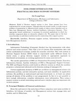
Fig. 4. FER of the relay technique versus the cooperative MISO technique
with two transmission nodes, noncoded QPSK modulation over a Rayleigh
channel, 120 b/frame, source–relay distance d1 = d/3, and power path loss
factor K = 2.
B. Performance Comparison of Cooperative Techniques
Because the cooperative relay and cooperative MIMO technique can exploit the diversity gain to increase the performance,
the performance of both techniques is much better than the
SISO technique, and the signal-to-noise ratio (SNR) needed is
smaller for the same BER requirement. Fig. 4 represents the
frame-error-rate (FER) performance comparison of the relay
(decode-and-forward and amplify-and-forward techniques) and
the cooperative MISO techniques for two transmit nodes with
the traditional SISO technique.
Because the SNRs of the cooperative MISO and relay techniques are smaller than the SISO technique, the two cooperative techniques can help reduce the transmission energy
consumption for the same transmission reliability in an energyconstrained traffic-signs wireless network. This energy efficiency of cooperative MIMO and relay techniques is very
useful for a typical medium- to long-distance transmission in
ITS application, where the transmission energy consumption
dominates the total consumption of a wireless node.
The nature of STBCs [14], [15] considers that signals from
different transmit antennas must synchronously be received at
each cooperative node to perform the orthogonal combination.
Furthermore, the clock of each wireless node can be drifted
during transmission times, and the transmission delay can vary
for each MIMO channel. Consequently, it is impossible to have
a perfectly synchronized transmission in distributed wireless
nodes, leading to an unsynchronized received signal at the
reception node. The effect of the transmission synchronization
error is the superposition of the signal pulses from each node,
shifted by the corresponding time delay, at the receiver. After
the synchronization and the signal sampling, intersymbol interference (ISI) between the unsynchronized sequences appears,
and the space–time sequences from the different nodes are
no longer orthogonal. The orthogonal combination of STBCs
cannot be performed, which leads to the amplitude decrease of
the desired signal and generates more interferences in the final
estimated symbols [16].
The effect of transmission synchronization in the performance of the cooperative MIMO technique for the case of
662
IEEE TRANSACTIONS ON INTELLIGENT TRANSPORTATION SYSTEMS, VOL. 12, NO. 3, SEPTEMBER 2011
Fig. 6.
Multihop SISO transmission between the infrastructure and a vehicle.
Fig. 7.
Relay transmission between the infrastructure and a vehicle.
Fig. 5. Effect of the transmission synchronization error on the performance of
the cooperative MISO systems with two transmit nodes N = 2 and Alamouti
STBC over a Rayleigh fading channel.
two transmit nodes is presented in Fig. 5. The performance
degradation increases with the transmission synchronization
error range. The cooperative MIMO system is rather tolerant
for a small range of transmission synchronization errors, and
the degradation is negligible for a synchronization error range
as small as 0.25Ts (and small for an error range as small as
0.5Ts ). For a small transmission synchronization error range,
the performance degradation is small enough to keep the energy efficiency advantage of the cooperative MIMO system
over the SISO and multihop SISO techniques. However, the
performance degradation is significant for transmission synchronization errors as large as 0.75Ts . In this case, a more complex distributed STBC or an efficient space–time combination
technique can be used to retain the performance of cooperative
MIMO in the presence of a transmission synchronization error.
C. Cooperative Transmission Schemes in the CAPTIV Project
In several communication scenarios in ITS, the transmission
between the infrastructure and the vehicles is usually from a
medium to long distance, and a direct transmission, if possible, would need too much transmission energy. A traditional
multihop routing technique can be used for such transmissions,
but it is not efficient enough in terms of energy consumption in
several cases. By exploiting the diversity transmission to reduce
the transmission energy consumption, the relay and cooperative
MIMO techniques are the better strategies in terms of energy
efficiency.
Considering that the circle and the rectangle stand, respectively, for the road sign and the vehicle in the transport system,
some cooperative transmission strategies, as illustrated in the
following figures, have been proposed for energy efficiency
transmissions in CAPTIV.
1) SISO Multihop Transmission: The most simple cooperation scheme is the multihop SISO transmission, as shown
in Fig. 6. Instead of the transmission over a long distance
from source node S to destination node D, a message from
a road sign (source node S) at a junction can be transmitted
through multiple road signs (cooperation nodes) to a vehicle
(destination node D). Multihop transmission can significantly
Fig. 8. Cooperative MISO transmission between the infrastructure and a
vehicle.
save the transmission energy consumption with the cost of more
circuit energy consumption.
2) Relay Transmission: In Fig. 7, a message from the road
sign can be transmitted to the vehicle (destination node D) and
another road sign (relay node R). Then, the message is relayed
from this relay road sign to the vehicle for signal combination.
The transmission diversity gain of the relay technique helps
decrease the transmission power for the same error rate requirement so that it reduces the transmission energy consumption.
This technique is more energy efficient than multihop SISO for
medium-range transmissions.
3) Cooperative MIMO Transmission: The cooperative
MIMO technique is an energy-efficient cooperative technique
for medium- and long-range transmissions [9]. The cooperative
MIMO technique exploits the diversity gain of the MIMO
space–time coding technique in distributed wireless networks
to reduce the transmission energy consumption. Depending on
the system topology (the available nodes) and the transmission
distance, the optimal selection of transmit and receive
nodes number can be chosen to minimize the total energy
consumption.
As illustrated in Fig. 8, a road sign node S can cooperate
with its neighbor road signs to employ a cooperative MISO
NGUYEN et al.: ENERGY-EFFICIENT COOPERATIVE TECHNIQUES FOR I2V COMMUNICATIONS
663
Fig. 9. Cooperative MIMO transmission between the infrastructure and a
vehicle.
Fig. 12. Transmitter and receiver blocks with N transmit and M receive
antennas.
TABLE I
SNR R EQUIREMENT OF THE C OOPERATIVE MIMO T ECHNIQUE FOR
−3
FER = 10
R EQUIREMENT AND A R AYLEIGH FADING C HANNEL
Fig. 10. Cooperative MIMO transmission between one infrastructure and
another infrastructure.
(and cooperate together) to perform a multihop cooperative
MIMO transmission.
III. E NERGY E FFICIENCY OF C OOPERATIVE S TRATEGIES
A. Energy Consumption Model
Fig. 11. Multihop cooperative MIMO transmission between the infrastructure
and a vehicle.
technique to transmit a message to the vehicle (destination
node D).
As shown in Fig. 9, the road sign node S and the vehicle
node D can cooperate with their respective neighbor road
signs to employ a cooperative MIMO transmission over a
long distance. Because the vehicles do not have the surface
and energy consumption constraints, multiple antennas can
easily be integrated in a vehicle to deploy the cooperative
MIMO schemes without the need of the cooperative reception
phase [9].
Another example of cooperative MIMO transmission in
CAPTIV is shown in Fig. 10, where the road sign node S can
cooperate with other road signs in one junction to transmit
the message by using a cooperative MIMO technique to the
cooperative reception road signs in the other junction.
4) Multihop Cooperative MIMO Transmission: For a longdistance communication, the cooperative MIMO technique
with the number of transmit and receive nodes greater than 2
has energy consumption advantages [9], but this scenario cannot always be employed because of the lack of available nodes
at the junctions. In this condition, a multihop technique using
cooperative MIMO for each transmission hop is a suitable
solution. As an example, for a communication between two
crossroads with a distance greater than 1 km in Fig. 11, two road
signs in the middle of the transmission line can be employed
For a traditional MIMO system (noncooperative MIMO
system) with N transmit and M receive antennas (N transmit
antennas and M receive antennas are integrated into one transmitter and one receiver), the typical radio frequency (RF) system block of transmitters and receivers is shown in Fig. 12. The
total power consumption of a typical MIMO system consists of
the following two components: 1) the transmission power Ppa
of the power amplifier and 2) the circuit power Pc of all RF
circuit blocks.
Ppa depends on the output transmission power Pout . If the
channel is a square-law path loss (power loss factor K = 2),
the transmission power needed can be calculated as
Pout (d) = E¯b Rb ×
(4πd)2
M l Nf
Gt Gr λ2
(1)
where E¯b is the required mean energy per bit for ensuring a
given error rate requirement, Rb is the bit rate, and d is the
transmission distance. Gt and Gr are the transmission and
reception antenna gains, respectively, λ is the carrier wave
length, Ml is the link margin, and Nf is the noise figure
receiver, which is defined as Nf = Mn /N0 , where N0 is the
single-side thermal noise power spectral density (PSD), and
Mn is the PSD of the total effective noise at receiver input.
Depending on the number of transmit and receive antennas
(N and M ) and the PSD of thermal noise N0 , E¯b can be
calculated based on the SN R value as given in Table I for the
FER requirement FER = 10−3 and the performance result in
Fig. 4.
The power consumption Ppa can be approximated as
Ppa = (1 + α)Pout
(2)
664
IEEE TRANSACTIONS ON INTELLIGENT TRANSPORTATION SYSTEMS, VOL. 12, NO. 3, SEPTEMBER 2011
where α = (ξ/η) − 1, with η being the drain efficiency of
the RF power amplifier and ξ being the peak-to-average ratio
(PAR), which depends on the modulation scheme and the
associated constellation size. Indeed, the power consumption of
the amplifier is always higher than the effective output power.
The total circuit power consumption of N transmit and M
receive antennas is given by
TABLE II
S YSTEM PARAMETERS FOR THE E NERGY C ONSUMPTION E VALUATION
Pc ≈ N (PDAC + Pmix + Pf ilt + Psyn )
+ M (PLN A + Pmix + PIF A + Pf ilr + PADC + Psyn ) (3)
where PDAC , Pmix , PLN A , PIF A , Pf ilt , Pf ilr , PADC , and
Psyn stand, respectively, for the power consumption values
of the digital-to-analog converter, the mixer, the low-noise
amplifier, the intermediate-frequency amplifier, the active filter
at the transmitter and the receiver, the analog-to-digital converter, and the frequency synthesizer. The power consumption
of signal processing blocks in the transmitter and the receiver is
typically much smaller than the consumption of RF blocks. It is
considered omitted in this estimation for simplicity.
The energy consumption of the traditional MIMO system
EMIMO can be obtained as
EMIMO = (Ppa + Pc )
Nb
.
Rb
(4)
The energy consumption of the SISO technique or one hop
of the SISO technique is the case that N = M = 1. The energy
consumption of one transmission phase (from nodes S to R and
from nodes R to D) of the relay technique can be calculated
similar to the SISO technique case.
For a cooperative MIMO system with N transmit and M
receive nodes, there are three communication phases: 1) the
data exchange phase; 2) the MIMO transmission phase; and
3) the cooperative reception phase. The energy consumption
of the MIMO transmission phase can be calculated similar
to the noncooperative MIMO case. The total energy consumption must include the energy consumption of cooperative
data exchanges and cooperative reception phases. The extra
cooperative energy consumption at the transmission EcoopTx
and reception Ecoop Rx sides can be calculated based on the
noncooperative energy consumption model [9].
The total energy consumption of a cooperative MIMO system with N transmit and M receive nodes is
Etotal = EcoopTx + EMIMO + EcoopRx .
(5)
For the case of cooperative MISO transmission (M = 1),
there are only two first-communication phases, which means
that the energy consumption of the reception phase EcoopRx is
zero.
B. Energy Consumption Comparison
For energy consumption estimation, evaluation, and comparison, the reference energy model in [17] with the system
parameters in Table II is used in this paper. More details on
the energy consumption calculation using this reference model
can be consulted in [9]. Figs. 6–11 represent the total energy
Fig. 13. Energy consumption of SISO versus the cooperative MISO technique
with two transmission nodes, power path loss factor K = 2, FER = 10−3 , and
Rayleigh fading channel.
consumption to transmit 107 b with the FER requirement
FER = 10−3 from a source node S to a destination node D
separated by a distance d (over a Rayleigh fading channel). The
local distance between cooperative nodes in the cooperative
MIMO techniques is dm = 5 m, and the source–relay distance
in the relay techniques is d1 = d/3.
1) Multihop SISO Versus Cooperative MISO Techniques:
The energy consumption comparison between multihop SISO
and the cooperative MISO is presented in Fig. 13 with the
optimal hop distance dhop = 25 m. At the transmission distance
d = 100 m (four hops), the multihop technique can save 53%
of the total energy consumption of the SISO system.
The multihop technique is more efficient than the SISO
transmission. However, the multihop SISO system is 69% less
energy efficient than the cooperative 2–1 MISO system. At
distance d = 100 m, 85% energy is saved by using the 2–1
cooperative MISO strategy instead of SISO. Note that the total
energy consumption is the consumption of all nodes and not
only one source node. The total energy saving is 69% or 85%
for the whole network by using cooperative techniques. The
transmission energy consumption (which is always greater than
the reception energy consumption for long distance) is shared
by all cooperative transmission nodes. Moreover, because the
multihop system needs four hops for signal transmission to
the destination node, the transmission delay of the multihop
technique is much more than the cooperative MISO technique,
which typically costs two phases of transmission.
Because the performance gain increases with the number
of cooperative transmission nodes in cooperative MIMO techniques, the cooperative MISO 3–1 or MISO 4–1 is more
NGUYEN et al.: ENERGY-EFFICIENT COOPERATIVE TECHNIQUES FOR I2V COMMUNICATIONS
Fig. 14. Energy consumption of the cooperative MISO technique with two,
three, and four transmission nodes, power path loss factor K = 2, FER =
10−3 , and Rayleigh fading channel.
efficient than the cooperative MISO 2–1 or MISO 3–1 at d =
180 m or d = 300 m, respectively, as shown in Fig. 14.
If all the RF parameters and the transmission distance are
fixed, the transmission energy consumption depends on the
required energy per bit Eb and the power path loss factor of
the channel [as shown in (1)]. If the FER required increases
(less reliable transmission), the required SNR and transmission
energy consumption will decrease, reducing the energy efficiency advantage of the cooperative MIMO over the SISO and
multihop SISO techniques. Otherwise, if the path loss factor
K increases (e.g., in an urban environment), the transmission
energy consumption quickly increases (as a power function
of the path loss factor K). Because the cooperative MIMO
technique efficiently helps reduce the transmission energy, the
advantage of cooperation increases. As far as the frequency
band is concerned, if the frequency fc = 5.8 GHz (which
was elected by the European Union for ITS applications and
is used in the delicate short-range communication technology) is considered instead of the reference model frequency
2.5 GHz used in this paper, the transmission energy consumption increases by (5.8/2.5)K times, and the cooperative MIMO
technique will probably be more efficient.
Because the nodes are physically separated in a cooperative
MIMO system, their different respective clocks lead to desynchronized transmission and reception. This condition generates
ISI, decreases the desired signal amplitude at the receiver, and
makes it more difficult to estimate the channel-state information
(CSI). At the reception side, each cooperative node has to
forward its received signal through the wireless channel to the
destination node for signal combination, which leads to additional noise in the final received signal. The effect of synchronization error at the transmission side and this additive noise
at the cooperative reception side lead to some performance
degradations of the cooperative MIMO system [13]. The transmission energy needs to be increased for the same error rate
requirement, which will lead to an increase in the transmission
energy and the total energy consumption.
The energy consumption of the cooperative phase (which
depends on the cooperative distance dm ) is much smaller than
665
Fig. 15. Energy consumption of the cooperative MISO 2–1 with different
cooperative transmission distances dm = 5, 10, and 20 m, FER = 10−3
requirement, and Rayleigh block-fading channel with power path loss factor
K = 2.
Fig. 16. Total energy consumption of the cooperative MIMO with different reception techniques versus the cooperative MISO, ∆Tsyn = 0.25Ts ,
FER = 10−3 requirement, and Rayleigh fading channel with power path loss
factor K = 2.
the consumption of the MIMO transmission phase for a longdistance transmission (because d
dm ). Therefore, the variation of the cooperative transmission distance dm slightly affects
the total energy consumption of the cooperative MIMO system.
Fig. 15 shows the energy consumption of the cooperative MISO
systems with different cooperative transmission distances dm =
5, 10, and 20 m.
2) Cooperative MIMO Versus Cooperative MISO Techniques: Fig. 16 shows the energy consumption comparison
between the cooperative MIMO system with two receive nodes
and the cooperative MISO systems 3–1 and 4–1. Forward and
combine, combine and forward
√ cooperative reception (with the
amplification factor Kc = 4) [13], and quantization reception
are used in the cooperative reception phase of the cooperative
MIMO technique, and the transmission synchronization error
range is considered ∆Ts = 0.25Ts .
The energy consumption of the cooperative MIMO 2–2 using
the forward-and-combine cooperative reception technique is
always smaller than the cooperative MISO 4–1 consumption
666
IEEE TRANSACTIONS ON INTELLIGENT TRANSPORTATION SYSTEMS, VOL. 12, NO. 3, SEPTEMBER 2011
Fig. 17. Optimal N − M transmit and receive antennas set selection as a
function of transmission distance, ∆Tsyn = 0.25Ts , FER = 10−3 requirement, and Rayleigh fading channel with power path loss factor K = 2.
Fig. 19. Energy consumption of the cooperative MISO technique as a function
of transmission synchronization error range, two transmission nodes, error rate
FER = 10−3 requirement, and Rayleigh fading channel with the power pathloss factor K = 2.
Fig. 18. Energy consumption of the relay technique versus the cooperative
MIMO technique with two transmission nodes, FER = 10−3 , power path
loss factor K = 2, and source–relay distance d1 = d/3.
and smaller than the cooperative MISO 3–1 consumption for
distances d > 130 m. At d = 500 m, there is a 25% energy
savings using the cooperative MIMO 2–2 technique instead of
the cooperative MISO 4–1 technique.
For each range of transmission distance d, based on the
energy calculation result, we can find the best N − M antenna
selection strategy of the cooperative MIMO technique in terms
of the energy consumption, as shown in Fig. 17. Note that,
given the transmission distance and other parameters such as
the quality of service (e.g., FER and the propagation channel),
the global energy consumption must be calculated for every
possible N − M configuration of cooperative MIMO by the
analytic formula to perform the selection.
3) Cooperative MISO Versus Relay Techniques: The performance of the relay techniques is limited by the decoding (or
signal processing) process at the relay nodes. The error bit (or
amplification noise) that occurs at the relay node cannot always
be corrected at the destination node. However, with the same
diversity gain, the performance of relay is always lower than
MISO space–time coding techniques. Therefore, in many cases,
the total energy consumption of the relay technique is higher
than the cooperative MISO technique. Fig. 18 shows the energy
consumption of the relay technique compared with the SISO
and cooperative MISO 2–1 techniques.
However, in the presence of transmission errors, the performance of the cooperative MISO technique decreases, leading to
the increase of transmission energy consumption. The energy
consumption of the cooperative MISO 2–1 as a function of
the transmission synchronization error range is illustrated in
Fig. 19. For a small synchronization error range, the degradation is negligible, but it becomes significant for a large error
range, leading to a more required transmission energy [13] and
less energy efficiency, as illustrated in Fig. 19.
The advantage of the relay technique over the cooperative
technique is that the relay is not affected by the unsynchronized
transmission. Fig. 20 shows the energy consumption comparison of the cooperative 2–1 and relay techniques with the path
loss factor K = 3, and the transmission synchronization error
range ∆Tsyn is as large as 0.5Ts . In this condition, the relay
technique is clearly better than the cooperative MISO in terms
of energy consumption.
In the case that the number of cooperative transmission nodes
N is greater than two (e.g., three or four transmit nodes),
the relay technique typically needs N transmission phases to
transmit all signals from N − 1 relay nodes to the destination
node (if orthogonal frequency channels are not considered).
However, the cooperative MISO technique typically needs two
transmission phases (data exchange and MISO transmission
phases). The transmission delay of the relay technique is longer
than the cooperative MISO technique. However, the complexity
of the relay is less than the cooperative MISO.
IV. C ONCLUSION
Cooperative techniques can exploit the transmission diversity
gain to increase the performance or reduce the transmission
energy consumption of the system. Some cooperative strategies, which are based on the multihop, cooperative relay, and
cooperative MIMO techniques, have been proposed to deploy
energy-efficient transmissions between the road infrastructures
and vehicles in CAPTIV.
In this paper, it has been shown that the cooperative MISO
and MIMO techniques are more energy efficient than the
NGUYEN et al.: ENERGY-EFFICIENT COOPERATIVE TECHNIQUES FOR I2V COMMUNICATIONS
Fig. 20. Energy consumption of the relay technique versus the cooperative
MISO technique with two transmission nodes N = 2, power path loss factor
K = 3, FER = 10−2 , transmission synchronization error range ∆Tsyn =
0.5Ts , and source–relay distance d1 = d/3.
SISO and traditional multihop SISO techniques for mediumand long-range transmissions. An optimal cooperative MIMO
scheme selection has also been presented to find the optimal N − M antenna configuration for a given transmission
distance.
Cooperative relay techniques provide attractive benefits for
wireless distributed systems when the temporal and spatial
diversity can be exploited to reduce the transmission energy
consumption. Relay techniques are more efficient than the SISO
technique but are still less efficient than the cooperative MISO
techniques in terms of energy consumption. The performance
of the relay techniques is not as good as the cooperative MISO
techniques for the same SNR. However, the relay techniques
are not affected by the unsynchronized transmission scheme.
When the transmission synchronization error becomes significant, the performance of the relay techniques is better than the
performance of the cooperative MISO, leading to better energy
efficiency.
667
[8] S. Cui, A. Goldsmith, and A. Bahai, “Energy efficiency of MIMO and
cooperative MIMO techniques in sensor networks,” IEEE J. Sel. Areas
Commun., vol. 22, no. 6, pp. 1089–1098, Aug. 2004.
[9] T. Nguyen, O. Berder, and O. Sentieys, “Cooperative MIMO schemes
optimal selection for wireless sensor networks,” in Proc. 65th IEEE VTC,
2007, pp. 85–89.
[10] K. Ito, N. Itoh, K. Sanda, and Y. Karasawa, “A novel MIMO STBC
scheme for intervehicle communications at intersection,” in Proc. 63rd
IEEE VTC, 2006, vol. 6, pp. 2937–2941.
[11] S. Konkaew, M. Chamchoy, and S. Promwong, “The impact of path
loss on cooperative MIMO transmission scheme for intelligent transport
system,” in Proc. ISCIT, 2006, pp. 516–520.
[12] O. Berder, P. Quemerais, O. Sentieys, J. Astier, T. Nguyen, J. Menard,
G. Le Mestre, Y. Le Roux, Y. Kokar, G. Zaharia, R. Benzerga, X. Castel,
M. Himdi, G. El Zein, S. Jegou, P. Cosquer, and M. Bernard, “Cooperative
communications between vehicles and intelligent road signs,” in Proc. 8th
Int. Conf. ITST, 2008, pp. 121–126.
[13] T. Nguyen, O. Berder, and O. Sentieys, “Impact of transmission synchronization error and cooperative reception techniques on the performance of
cooperative MIMO systems,” in Proc. IEEE ICC, Beijing, China, 2008,
pp. 4601–4605.
[14] S. Alamouti, “A simple transmit diversity technique for wireless communications,” IEEE J. Sel. Areas Commun., vol. 16, no. 8, pp. 1451–1458,
Oct. 1998.
[15] V. Tarokh, H. Jafarkhani, and A. R. Calderbank, “Space–Time block
codes from orthogonal designs,” IEEE Trans. Inf. Theory, vol. 45, no. 5,
pp. 1456–1467, Jul. 1999.
[16] S. Jagannathan, H. Aghajan, and A. Goldsmith, “The effect of time synchronization errors on the performance of cooperative MISO systems,” in
Proc. IEEE GlobeCom Workshops, 2004, pp. 102–107.
[17] S. Cui, A. J. Goldsmith, and A. Bahai, “Modulation optimization under
energy constraints,” in Proc. IEEE Int. Conf. Commun., Anchorage, AK,
May 2003, pp. 2805–2811.
Tuan-Duc Nguyen received the M.Sc. degree from
Telecom ParisTech University, Paris, France, and
the Ph.D. degree from the University of Rennes 1,
Rennes, France, in 2005 and 2009, respectively.
In 2009, he was a Postdoctoral Researcher in
cooperative communications for wireless sensor networks with the Institut de Recherche en Informatique
et Systèmes Aléatoires (IRISA) Research Center,
University of Rennes 1. Since 2010, he has been a
Lecturer and Researcher with the School of Electrical Engineering, Ho Chi Minh City International
University, Vietnam National University, Ho Chi Minh City, Vietnam. His research interests include cooperative communications, wireless sensor networks,
and wireless ad hoc networks.
R EFERENCES
[1] J. Laneman and G. Wornell, “Energy-efficient antenna sharing and relaying for wireless networks,” in Proc. IEEE Wireless Commun. Networking
Conf., 2000, vol. 1, pp. 7–12.
[2] A. Sendonaris, E. Erkip, and B. Aazhang, “User cooperation
diversity—Part I: System description,” IEEE Trans. Commun., vol. 51,
no. 11, pp. 1927–1938, Nov. 2003.
[3] J. Laneman, D. Tse, and G. Wornell, “Cooperative diversity in wireless
networks: Efficient protocols and outage behavior,” IEEE Trans. Inf. Theory, vol. 50, no. 12, pp. 3062–3080, Dec. 2004.
[4] H. Ilhan, I. Altunbas, and M. Uysal, “Cooperative diversity for relayassisted intervehicular communication,” in Proc. IEEE Veh. Technol.
Conf., 2008, pp. 605–609.
[5] M. Dohler, E. Lefranc, and H. Aghvami, “Space–Time block codes for
virtual antenna arrays,” in Proc. 13th IEEE Int. Symp. Personal, Indoor
Mobile Radio Commun., 2002, vol. 1, pp. 414–417.
[6] X. Li, “Energy-efficient wireless sensor networks with transmission diversity,” Electron. Lett., vol. 39, no. 24, pp. 1753–1755, Nov. 2003.
[7] J. Laneman and G. Wornell, “Distributed space–time-coded protocols for
exploiting cooperative diversity in wireless networks,” IEEE Trans. Inf.
Theory, vol. 49, no. 10, pp. 2415–2425, Oct. 2003.
Olivier Berder received the B.S., M.S., and Ph.D.
degrees in electrical engineering from the University
of Bretagne Occidentale, Brest, France, in 1998,
1999, and 2002, respectively.
From 2002 to 2004, he was with the Laboratory for Electronics and Telecommunication Systems
(LEST–UMR CNRS 6165), Brest. From October
2004 to February 2005, he was with the Speech and
Sound Technologies and Processes Laboratory, FT
R&D, Lannion, Brittany, France. In March 2005,
he was with the École Nationale Supérieure des
Sciences Appliquées et de Technologie (ENSSAT)–University of Rennes 1,
Rennes, France. He is currently an Assistant Professor with the Institut de
Recherche en Informatique et Systèmes Aléatoires (IRISA), University of
Rennes 1. His research interests focus on multiantenna systems and cooperative
techniques for mobile communications and wireless sensor networks.
668
IEEE TRANSACTIONS ON INTELLIGENT TRANSPORTATION SYSTEMS, VOL. 12, NO. 3, SEPTEMBER 2011
Olivier Sentieys (M’03) received the M.Sc. and
Ph.D. degrees in electrical engineering (signal
processing) from the University of Rennes 1,
Rennes, France, in 1990 and 1993, respectively.
After completing his Habilitation thesis in 1999,
he was with the Graduate School of Electronics
Engineering of the École Nationale Supérieure des
Sciences Appliquées et de Technologie (ENSSAT),
University of Rennes, as a Full Professor in 2002.
He currently leads the CAIRN Research Team with
the Institut National de Recherche en Informatique et
en Automatique (INRIA; French National Institute for Research in Computer
Science and Control) and the Institut de Recherche en Informatique et Systèmes
Aléatoires (IRISA), University of Rennes 1. His research interests include finite
arithmetic effects, low-power and reconfigurable system on chip, the design of
wireless communication systems, and cooperation in mobile systems. He is a
member of the editorial board of the Journal of Low Power Electronics. He is
the author or a coauthor of more than 150 journal publications or peer-reviewed
conference proceedings and is the holder of five patents.
Prof. Sentieys is the President of the French Chapter of IEEE Circuits
and Systems (CAS) Society and a member of the Association for Computing
Machinery (ACM). He was a Publicity Cochair of the 2010 IEEE International
Symposium on Circuits and Systems and has been on several conference
program committees, including the IEEE International Symposium on Quality
Electronic Design, the IEEE International Symposium on Design and Diagnostics of Electronic Circuits and Systems, the IEEE Vehicular Technology Conference, the International Conference on Design and Technology of Integrated
Systems, the Conference on Design of Circuits and Integrated Systems, and the
IEEE Northeast Workshop on Circuits and Systems.