DSpace at VNU: Performance Evaluation of a Multi-User MIMO System With Prediction of Time-Varying Indoor Channels
Bạn đang xem bản rút gọn của tài liệu. Xem và tải ngay bản đầy đủ của tài liệu tại đây (1.73 MB, 9 trang )
IEEE TRANSACTIONS ON ANTENNAS AND PROPAGATION, VOL. 61, NO. 1, JANUARY 2013
371
Performance Evaluation of a Multi-User MIMO
System With Prediction of Time-Varying Indoor
Channels
Huu Phu Bui, Yasutaka Ogawa, Fellow, IEEE, Toshihiko Nishimura, Member, IEEE, and
Takeo Ohgane, Member, IEEE
Abstract—In this paper, the performance of a multi-user
multiple-input multiple-output (MIMO) system in time-varying
channels is evaluated using measurement data. We consider the
multi-user MIMO system using a block diagonalization (BD)
scheme and an eigenbeam-space division multiplexing (E-SDM)
technique. In an ideal case, the BD scheme eliminates inter-user
interference, and the E-SDM technique suppresses inter-stream
interference. In actual radio environments, however, channels
change over time. This causes interference in the multi-user
MIMO system even though the BD scheme and the E-SDM
technique are used. To overcome this problem, the authors have
developed a simple channel prediction scheme on the basis of
a linear extrapolation and have demonstrated its effectiveness
by computer simulations assuming the Jakes’ model. To verify
the performance of the channel prediction scheme in actual
environments, we conducted a measurement campaign in indoor
environments and measured a large amount of channel data.
Using these data, we examined the channel transition and channel
tracking with the prediction method. Then we obtained the
bit-error rate (BER) performance. The prediction technique was
shown to track the channel and improve the BER performance
almost to that in the ideal time invariant case.
Index Terms—Block diagonalization, channel prediction,
Doppler frequency, eigenbeam-space division multiplexing,
multi-user MIMO system, time-varying environment.
I. INTRODUCTION
M
ULTIPLE-INPUT multiple-output (MIMO) systems
have been extensively studied over the last decade
because they provide high data rate transmission without
increasing the frequency bandwidth [1], [2]. Attention is currently focused not only on single-user MIMO systems but also
on multi-user ones that accommodate multiple mobile stations
Manuscript received January 15, 2012; revised August 08, 2012; accepted
August 08, 2012. Date of publication August 23, 2012; date of current version
December 28, 2012. The work of H. P. Bui was supported in part by the Vietnam
National Foundation for Science and Technology Development (NAFOSTED)
under Grant 102.02-2011.23. The results in this paper were presented in part at
the 2011 IEEE AP-S International Symposium, Spokane, WA, July 2011.
H. P. Bui is with the National Key Lab of Digital Control & System Engineering, University of Technology, Vietnam National University, Hochiminh
City, Vietnam (e-mail: ).
Y. Ogawa is with the Graduate School of Information Science and Technology, Hokkaido University, Sapporo, Japan (e-mail:
jp).
T. Nishimura and T. Ohgane are with the Graduate School of Information Science and Technology, Hokkaido University, Japan (e-mail:
; ).
Color versions of one or more of the figures in this paper are available online
at .
Digital Object Identifier 10.1109/TAP.2012.2214995
(MSs) simultaneously [3]. Furthermore, capacity of multi-user
MIMO channels has been investigated on the basis of measurements [4]–[6]. In MIMO systems, we may have multiple-stream
transmission between a base station (BS) and a MS. Thus, we
may have inter-stream interference (IStI). In multi-user MIMO
systems, we may encounter inter-user interference (IUI) in
addition to the IStI. These interferences severely degrade
MIMO system, especially in a downlink transmission scenario,
because each MS usually has fewer antennas than a BS and
does not have enough degrees of freedom to suppress the interferences. A block diagonalization (BD) scheme can eliminate
the IUI [7]–[9]. This scheme decomposes a multi-user MIMO
channel into multiple independent single-user MIMO channels
by forcing the interference to a user from the remaining users
to be zero. In addition, to suppress IStI in each single-user
MIMO channel, an eigenbeam-space division multiplexing
(E-SDM) technique can be applied [10], which is also called
a singular value decomposition (SVD) system [11] or MIMO
eigenmode transmission system [12]. Therefore, combining the
BD scheme and the E-SDM technique is expected to realize
efficient transmission in a multi-user MIMO system.
In the downlink multi-user MIMO systems, we need downlink channel state information (CSI) at the BS (transmitter). In
a frequency division duplex (FDD) system, the CSI must be
fed back from MSs. In this case, the CSI at an actual transmission instant may be outdated because of the feedback delay. In a
time division duplex (TDD) system, we can obtain the downlink
CSI from the uplink signal because channel reciprocity holds.
Even in the TDD system, we encounter the outdated CSI when
the time interval between the uplink channel and the downlink
transmission cannot be neglected. The effect of CSI delay is a
critical issue and has been reported in the literature [13] and the
references therein. Also, single-user MIMO systems [14]–[16]
and multi-user ones [17], [18] have been investigated on the
basis of measurements. We conducted measurement campaigns
for a single-user MIMO system [19] and a multi-user one [20]
in time-varying indoor environments. On the basis of the measured channel data, we evaluated bit-error rate (BER) performance of MIMO systems. These data show that the outdated
CSI much more significantly affects multi-user MIMO cases
than single-user ones because MSs have fewer antennas than
a BS.
To mitigate the effect of outdated CSI, channel prediction
techniques have been developed [16], [21]–[23]. One typical
scheme is a linear predictor based on an AR model, and another
uses sinusoids composed of the scattered signals.
0018-926X/$31.00 © 2012 IEEE
372
IEEE TRANSACTIONS ON ANTENNAS AND PROPAGATION, VOL. 61, NO. 1, JANUARY 2013
We proposed linear and second-order channel prediction
schemes for a single-user MIMO E-SDM system that use only
two and three channel data, respectively [24]. The computational complexity of the method is smaller than the other
schemes. Also, we applied the linear channel prediction scheme
to a multi-user MIMO E-SDM system, and examined the BER
performance using computer-generated data. The simulations
were done assuming the Jakes’ model, and it was shown
that the channel prediction method significantly improves the
BER performance [25]. In actual propagation environments,
however, we may have line-of-sight (LOS) components, and
scatterers are not distributed uniformly. In the simulations, it
was assumed that the antenna arrays at the BS and MSs consist
of omnidirectional antenna elements. However, even though a
single isolated antenna has an omnidirectional pattern, the antenna element in an array has a different one. This is due to the
effect of mutual coupling among antennas, and affects the BER
performance [19], [20]. They were ignored in the simulations.
Thus, the channel prediction method must be evaluated on the
basis of measurements. We conducted measurement campaigns
at a 5.2 GHz frequency band in indoor environments and
obtained a large amount of statistically stationary time-varying
channels. Using the data, we investigated the effect of the
channel prediction scheme and the BER performance for the
multi-user MIMO E-SDM system. The authors have reported a
portion of the results in [26]. In this paper, we present in detail
the effect of the MIMO channel prediction.
The paper is organized as follows. The next section describes
the multi-user MIMO system and the linear channel prediction. Section III then presents a detailed measurement setup for
our experiment. After that, Section IV details the behavior of
channel transitions and predictions. Next, Section V evaluates
the BER of the MIMO system in time-varying indoor channels.
Finally, Section VI provides the conclusions.
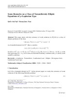
II. MULTI-USER MIMO SYSTEM AND CHANNEL PREDICTION
We briefly explain a downlink multi-user MIMO system
based on a combination of the BD scheme and the E-SDM
technique. For the sake of simplicity of explanation, we assume
a two-MS case as shown in Fig. 1. We also assume that the BS
and each MS have four and two antennas, respectively. This is
the same configuration as that we used in our measurements
that will be stated later. General and detail description of the
multi-user MIMO system is given in [25]. We express transmit
(TX) symbols for the MS1 and MS2 as
and
, respectively. Also,
and
denote the TX weight matrices
for the MS1 and MS2, respectively. The received signals at the
MS1 and MS2 are given by
(1)
(2)
where
and
denote 2 4 matrices for the channels between the BS and MS1 and those between BS and MS2, respectively.
and
denote thermal noise at MS1 and MS2,
respectively. The first terms in the equations are the desired signals for the MSs. The second terms are the interferences from
the other user, namely IUI.
Fig. 1. Multi-user MIMO system (Two-MS case).
In the BD scheme, the TX weights are determined in such a
way that the MSs do not receive any IUI. The second terms in
(1) and (2) are 0. Thus, we have
(3)
The TX matrices satisfying the above equations are given by
the SVD of the channel matrices of
and
. We introduce
and
. The columns in
form a basis set in the
matrices
null space of
. Similarly, the columns in
form a basis set
in the null space of
.
and
are obtained from rightand
,
singular vectors with the singular value of 0 for
respectively. In multipath-rich environments,
and
are
4 2 matrices. Using
and
, the TX weight matrices are
given by
(4)
and
denote 2 2 or 2 1 matrices. When
is a
where
2 2 matrix, 2-stream transmission is done from the BS to MS1,
whereas when
is a 2 1 matrix (vector), a single-stream
transmission is done. This is also the case with .
and
can be arbitrary in the BD scheme. That is, we can eliminate the
IUI using arbitrary matrices
and
. Thus, (1) and (2) can
be rewritten as
(5)
(6)
and
can be determined by the E-SDM
The optimum
technique as stated in the following. We introduce the equivalent single-user MIMO channel matrices
and
. They are 2 2 matrices in multipath-rich
environments. Substituting these matrices for (5) and (6), we
have
(7)
(8)
and
as the
From the above equations, we can consider
equivalent TX matrices for the MS1 and MS2, respectively.
BUI et al.: PERFORMANCE EVALUATION OF A MULTI-USER MIMO SYSTEM WITH PREDICTION OF TIME-VARYING INDOOR CHANNELS
Here, we introduce
SVD of
and
373
and
, which are given by the
as follows:
(9)
and
denote the diagonal singular value maHere,
trices, and
denotes the Hermitian matrix transpose.
Applying the E-SDM technique, the equivalent transmit
weight matrices
and
can be determined as
(10)
and
are the diagonal transmit power matrices for
where
the MS1 and MS2, respectively. The diagonal element is the
transmit power corresponding to the stream.
From (4) and (10), the TX weight matrices are given by
Fig. 2. Linear channel extrapolation scheme.
the last two successive uplink ACK packets. The channel is linearly extrapolated to the actual DL transmission time as shown
in Fig. 2, and the predicted value is given by
(12)
(11)
The optimum number of the streams, modulation schemes, and
power allocation are determined in such a way that the Chernoff
upper bound of BER has the lowest value [10].
At the MSs, to demultiplex the received signals, we use
weight matrices
and
, which realize the maximal ratio combining (MRC) or spatial filtering on the basis of
the minimum mean square error (MMSE) criterion. This is the
concept of the multi-user MIMO E-SDM scheme.
The TX weight matrices given by (11) do not interfere with
the other MS, and we do not have interference between streams.
That is, we have neither IUI nor IStI. Also, the resources can
be allocated optimally. However, in time-varying environments,
the channel matrices are a function of time. The channels at the
actual transmission time differ from those used to determine the
TX weight and allocate the resources. The outdated CSI does
not guarantee (3) and causes IUI. Also, we have interference between streams, and the resources may not be optimally allocated
any more. In the remainder of this paper, we assume that the
MSs have perfect CSI, and that the RX weight matrices
and
are determined by the MMSE criterion. Thus, when
the BS uses single-stream transmission for each MS, the MS receivers can cancel the IUI for the two-MS case shown in Fig. 1.
However, when multi-stream transmission is used, the interference cannot be suppressed at the MS sides and system performance can be seriously degraded.
Now, we describe the channel prediction scheme [25]. In this
paper, we assume a TDD system such as HIPERLAN/2 [27].
Also in 3GPP LTE and mobile WiMAX, TDD systems are standardized in addition to FDD ones [28], [29]. The channel is predicted by linear extrapolation as shown in Fig. 2. Uplink and
downlink signals are transmitted with a period of , which is
the frame duration in the TDD system. The BS estimates the
channels for the MSs using uplink ACK packets, and sends
downlink (DL) packets using the multi-user MIMO E-SDM
scheme. We assume that the ACK and DL packets are so short
that we can neglect the channel change in the packet duration.
In the prediction method, we first estimate the channel using
where is the time interval between the transmit weight matrix determination and the actual downlink packet transmission,
and
are the observed channel values from the
-th TX antenna of the BS to the -th RX antenna of the -th MS
at times and , respectively.
Note that the simplest way to obtain the channel for the downlink packet is not to extrapolate the channel but to use
.
We consider this to be the conventional method and call it the
“non-extrapolation” method. According to Fig. 2, the liner extrapolation method can provide more accurate channels than the
non-extrapolation one.
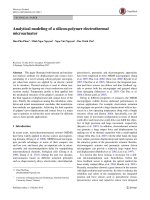
III. CHANNEL MEASUREMENT SETUP
The measurement campaign for the multi-user MIMO system
was carried out in a meeting room in a building of the Graduate
School of Information Science and Technology, Hokkaido University, as shown in Fig. 3. The measurement is the same as
that stated in [20]. A similar measurement was conducted for a
single-user MIMO system at the same site [19]. The walls of the
room were mostly plasterboard. We also had reinforced concrete
pillars, metal doors, and metal whiteboard. In the room, a 4-element TX and two 2-element RX linear arrays were placed on
three tables. The TX and RX correspond to the BS and MS stated
in the previous sections, respectively. The arrays consisted of
omnidirectional collinear antennas. The nominal gain of these
antennas on the horizontal plane was about 4 dBi. The distances
from the TX to RX1 and RX2 were 4 m, while the spacing between RX1 and RX2 was 3 m. Channels were measured for
all the TX and the RX antenna pairs through a vector network
analyzer (VNA), as shown in Fig. 4. RF switches at both the
TX and the RX sides were controlled by a personal computer
(PC) and selected a TX antenna and an RX antenna, respectively. Measured data were then saved on the computer. The unselected antennas were automatically connected to 50 dummy
loads. The measurement band was from 5.15 GHz to 5.40 GHz
(
), and we obtained 1,601 frequency
domain data with 156.25 kHz interval. The antenna spacing
374
IEEE TRANSACTIONS ON ANTENNAS AND PROPAGATION, VOL. 61, NO. 1, JANUARY 2013
Fig. 5. Array orientations. (a) TX- /RX- . (b) TX- /RX- .
Fig. 3. Measurement site (top view).
Fig. 4. Channel measurement system.
(AS) was 3 cm (half-wavelength at 5 GHz), and two array orientations along the - and the -axes, called TX- /RX- and
TX- /RX- , were examined as shown in Fig. 5. When there
were no metal partitions between the TX and RXs, we had a
LOS environment, as shown in Fig. 6(a). When there were partitions, we had a non-LOS (NLOS) one, as shown in Fig. 6(b).
On the RX side, two stepping motors were used to move the
two RX arrays along the - or -axis during the experiments.
These motors were controlled by a personal computer. Each step
of the motors corresponds to 0.0088 cm, and the RX arrays were
stopped at every 10 steps (equal to 0.088 cm). The channels
were measured at intervals of 0.088 cm, and we had a total of
500 spatial measurement points. As a result,
channel response matrices were obtained for each case
Fig. 6. Measurement environments. (a) LOS environment. (b) NLOS environment.
of the direction of the RX motion, the array orientation, and the
LOS/NLOS condition. The large amount of channel data was
measured to examine reliable BER performance. Note that the
measurement campaign was conducted while no one was in the
room to ensure statistical stationarity of propagation.
IV. TRANSITIONS AND PREDICTIONS OF CHANNEL
In this section, using the measured channel data, we investigate the behavior of channel transitions and predictions. As
BUI et al.: PERFORMANCE EVALUATION OF A MULTI-USER MIMO SYSTEM WITH PREDICTION OF TIME-VARYING INDOOR CHANNELS
375
Fig. 7. Channel transition and linear prediction (1). TX- /RX- , NLOS, RX2,
, RX motion along -axis,
. (a) Amplitude. (b) Phase.
Fig. 8. Channel transition and linear prediction (2). TX- /RX- , LOS, RX2,
, RX motion along -axis,
. (a) Amplitude. (b) Phase.
stated in the previous section, the channels were measured at
intervals of 0.088 cm. That is, we obtained channels as a function of location. We can transform them into channel data as a
function of time with a parameter of a maximum Doppler frequency. We assume that a mobile terminal is moving at a constant velocity . With a time interval
, the distance
that
the mobile terminal has moved is given by
(
). That is, the channel data at the measurement
points can be considered to be the data as a function of time at
intervals of 0.5 ms with
.
Figs. 7 and 8 show examples of channel transitions for
conditions described in the figure captions. They are the
channel between the TX antenna #1 and RX antenna #1 for the
RX2. The amplitudes in the figurers were normalized to the
amplitude for the single-user single-input single output (SISO)
LOS measurement in an anechoic chamber, with the distance
of 4 m between the TX and RX sides. The channels are seen
to change significantly during the interval of only 1 ms or
. The time interval of 1 ms corresponds
2 ms for
to the location interval of only 0.176 cm or 0.03 wavelengths
. That is, channels vary very rapidly in multifor
path-rich environments.
Next, we consider the liner channel prediction stated in Section II. In the remainder of this paper, we assume the frame duof 2 ms, as in the HIPERLAN/2 standard. The linearly
ration
extrapolated channels are also drawn in the figures. In this case,
and
hold. We can see that the
predicted channels track the actual ones well. The prediction
scheme improves the multi-user MIMO system performance as
will be described in the next section.
(13)
The maximum Doppler frequency
occurring during the mobile terminal’s motion is as follows:
(14)
where , , and denote the carrier frequency, the speed of
light, and the wavelength, respectively.
Assuming that the time interval between the adjacent measurement points (
) was 0.5 ms (
),
then from (14), we had
, where the carrier frequency was assumed to be the center of the measurement band
376
IEEE TRANSACTIONS ON ANTENNAS AND PROPAGATION, VOL. 61, NO. 1, JANUARY 2013
TABLE I
SIMULATION PARAMETERS
V. BER PERFORMANCE OF MULTI-USER MIMO SYSTEMS
Using the measured channel data, we conducted simulations
of multi-user MIMO E-SDM transmission and obtained the
BER performance. In this section, we describe the effect of
the channel prediction scheme in the indoor time-varying
environments. We assumed frequency-flat fading channels.
Table I lists simulation parameters. The data rate for each MS
was fixed constantly at 4 bps/Hz (bits per symbol duration).
Because the TX had four antennas and each RX had two antennas, we had either single-stream or two-stream transmission
for each RX. The modulation scheme was either 16QAM for
the single-stream transmission or QPSK for the two-stream
one. The resource control, namely determining the number of
streams, modulation scheme, and transmit power, was done in
such a way that the Chernoff upper bound of BER of each MS
had the lowest value [10]. The total transmit power per MS was
assumed to be equal. In this study, we focused on the effect of
the compensation for time-varying MIMO channels using the
linear extrapolation scheme. Thus, the uplink channels were
assumed to be estimated perfectly at the TX using the ACK
packets, and the effective downlink channels for the E-SDM
transmission were also assumed to be estimated perfectly at
both RXs. In addition to the above, we assumed that there is
neither an analogue circuit impairment nor a signal processing
one such as a quantization error.
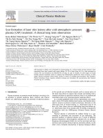
Fig. 9 shows the average BER performance of RX2 versus
normalized TX power for NLOS cases. The normalized TX
power is the TX power per MS normalized to the power yielding
average
of 0 dB in the case of the single-user SISO-LOS
measurement in an anechoic chamber stated in the previous section. Here,
is received signal energy per symbol, and
is noise power density. The BER performance was examined
for different maximum Doppler frequencies. The ideal case in
the figures shows the behavior for the maximum Doppler frequency of 0 Hz. We do not have channel changes in the ideal
case. As indicated in Table I, all the curves are for the delay
of 1 ms from the ACK packet. That is, we had a 1 ms interval between the determination of TX parameters including
the weights and the actual data transmission. The figures show
that when we do not use the channel prediction scheme, we have
Fig. 9. BER performance of multi-user MIMO systems for RX2 in NLOS environments. RX motion along -axis. (a) TX- /RX- . (b) TX- /RX- .
error floors the curves of which are denoted by “Non-extrapolation”. This means that if we use the outdated channels when the
ACK packet is received, we have poor BER performance. The
travel distances during 1 ms for
, 31, and 45.6 Hz
correspond to about 0.015, 0.03, and 0.045 wavelengths, respectively. Only a fraction of channel transition significantly affects
the BER performance even though the RX weights are determined by the MMSE criterion using the CSI without delay. On
the other hand, when we use the channel prediction scheme denoted by “Linear-extrapolation” in the figures, the error floor
disappears, and the BER performance is improved almost to that
in the ideal case.
As stated in Section II, when the TX uses two-stream
transmission to at least one RX, the interference cannot be suppressed because the RX has only two antennas. Table II shows
the percentage of streams for the maximum Doppler frequency
of 31 Hz and the normalized TX power of 30 dB. Two-stream
transmission to at least one RX ranges from 23% to 31%. This
was considered to seriously degrade BER performance when
the channel prediction method was not used.
Fig. 10 shows the BER performance for LOS cases. Compared to the NLOS cases shown in Fig. 9, the BER without the
channel prediction largely depends on the array orientation. The
BER performance for the TX- /RX- is much better than that
BUI et al.: PERFORMANCE EVALUATION OF A MULTI-USER MIMO SYSTEM WITH PREDICTION OF TIME-VARYING INDOOR CHANNELS
TABLE II
PERCENTAGE OF STREAMS IN NLOS ENVIRONMENTS. RX MOTION
ALONG -AXIS,
, NORMALIZED TX POWER OF
30 DB. (a) TX- /RX- . (b) TX- /RX-
377
TABLE III
PERCENTAGE OF STREAMS IN LOS ENVIRONMENTS. RX MOTION
ALONG -AXIS,
, NORMALIZED TX POWER OF
30 DB. (a) TX- /RX- . (b) TX- /RX-
for the TX- /RX- . As discussed in detail in [20], this is because higher received power was obtained with the TX- /RXorientation due to the mutual coupling between antennas. It is
seen that when the channel prediction scheme is used, the BER
performance is improved almost to that in the ideal case for both
array orientations.
Table III shows the percentage of streams for the LOS cases.
We can see that the single-stream transmission to each RX accounts for nearly 90% of the MIMO communications in the
LOS TX- /RX- case. That is, the single-stream transmission
was dominant in this condition. Also, the percentage of the twostream transmission to both RXs is 0.3% in this case, which is a
much lower value than those in the other cases. It is conjectured
that these resource allocations reduced the degradation due to
the interference and improved the BER performance.
The maximum Doppler frequencies of 15.5 Hz, 31 Hz, and
46.5 Hz correspond to the velocities of 0.88 m/s, 1.76 m/s,
and 2.64 m/s for the center of the measurement band of 5.275
GHz, respectively. These values are walking velocities, which
are reasonable in indoor environments. As stated previously, we
assumed that is 1 ms, which is also reasonable for a TDD
system such as HIPERLAN/2 standard. Thus, we can say that
the linear channel prediction scheme is effective for the TDD
system in indoor environments. For faster fading in outdoor environments, we will need more sophisticated channel prediction
schemes.
Fig. 10. BER performance of multi-user MIMO systems for RX2 in LOS environments. RX motion along -axis. (a) TX- /RX- . (b) TX- /RX- .
VI. CONCLUSIONS
We have investigated the channel prediction scheme for
the multi-user MIMO system using the measured channel
data. The measurement campaign was carried out at the 5.2
GHz frequency band in indoor environments. The channel
changes significantly with only a fraction of transitions such as
378
IEEE TRANSACTIONS ON ANTENNAS AND PROPAGATION, VOL. 61, NO. 1, JANUARY 2013
0.03 wavelengths, and the small channel transition seriously
degrades BER performance. In the LOS case, the behavior
depends on the array orientation due to the effect of mutual
coupling. We have shown that the channel prediction based on
the simple linear extrapolation can track the actual channel and
that the BER performance is improved in all scenarios almost
to that in the ideal time invariant case.
In this paper, we assumed perfect channel estimation at both
of the TX and RX sides. Erroneous channel prediction due to the
channel estimation error at the TX will increase IUI and IStI, and
will degrade the resource control. The channel estimation error
at the RX causes erroneous RX weight determination. Considerations on the performance degradation due to the channel estimation error are our future work.
REFERENCES
[1] E. Telatar, “Capacity of multi-antenna Gaussian channels,” Eur. Trans.
Telecomm., vol. 10, no. 6, pp. 585–589, Nov./Dec. 1999.
[2] A. J. Paulraj, D. A. Gore, R. U. Nabar, and H. Bölcskei, “An overview
of MIMO communications — A Key to gigabit wireless,” Proc. IEEE,
vol. 92, no. 2, pp. 198–218, Feb. 2004.
[3] D. Gesbert, M. Kountouris, R. W. Heath Jr., C. B. Chae, and T. Sälzer,
“Shifting the MIMO paradigm,” IEEE Signal Process. Mag., vol. 24,
no. 5, pp. 36–46, Sep. 2007.
[4] G. Bauch, J. B. Anderson, C. Guthy, M. Herdin, J. Nielsen, J. A.
Nossek, P. Tejera, and W. Utschick, “Multiuser MIMO channel
measurements and performance in a large office environment,” in
Proc. IEEE Wireless Comm. and Net. Conf. (WCNC2007), Mar. 2007,
pp. 1902–1907.
[5] J. Koivunen, P. Almers, V.-M. Kolmonen, J. Salmi, A. Richter, F.
Tufvesson, P. Suvikunnas, A. F. Molisch, and P. Vainikainen, “Dynamic multilink indoor MIMO measurements at 5.3 GHz,” presented
at the 2nd Eur. Conf. Antennas and Propagation (EuCAP 2007), Nov.
2007.
[6] F. Kaltenberger, M. Kountouris, D. Gesbert, and R. Knopp, “On the
trade-off between feedback and capacity in measured MU-MIMO
channels,” IEEE Trans. Wireless Commun., vol. 8, no. 9, pp.
4866–4875, Sep. 2009.
[7] L. U. Choi and R. D. Murch, “A transmit preprocessing technique
for multiuser MIMO systems using a decomposition approach,” IEEE
Trans. Wireless Commun., vol. 3, no. 1, pp. 20–24, Jan. 2004.
[8] Q. H. Spencer, A. L. Swindlehurst, and M. Haardt, “Zero-forcing
methods for downlink spatial multiplexing in multiuser MIMO channels,” IEEE Trans. Signal Process., vol. 52, no. 2, pp. 461–471, Feb.
2004.
[9] Q. H. Spencer, C. B. Peel, A. L. Swindlehurst, and M. Haardt, “An
introduction to the multi-user MIMO downlink,” IEEE Commun. Mag.,
pp. 60–67, Oct. 2004.
[10] K. Miyashita, T. Nishimura, T. Ohgane, Y. Ogawa, Y. Takatori, and
K. Cho, “High data-rate transmission with eigenbeam-space division
multiplexing (E-SDM) in a MIMO channel,” in Proc. IEEE VTC 2002Fall, Sep. 2002, vol. 3, pp. 1302–1306.
[11] G. Lebrun, J. Gao, and M. Faulkner, “MIMO transmission over a timevarying channel using SVD,” IEEE Trans. Wireless Commun., vol. 4,
no. 2, pp. 757–764, Mar. 2005.
[12] S. H. Ting, K. Sakaguchi, and K. Araki, “A robust and low complexity
adaptive algorithm for MIMO eigenmode transmission system with experimental validation,” IEEE Trans. Wireless Commun., vol. 5, no. 7,
pp. 1775–1784, Jul. 2006.
[13] K. Huang, R. W. Heath Jr., and J. G. Andrews, “Limited feedback
beamforming over temporally-correlated channels,” IEEE Trans.
Signal Process., vol. 57, no. 5, pp. 1959–1975, May 2009.
[14] J. W. Wallace and M. A. Jensen, “Time-varying MIMO channels: Measurement, analysis, and modeling,” IEEE Trans. Antennas Propagat.,
vol. 54, no. 11, pp. 3265–3273, Nov. 2006.
[15] R. C. Daniels, K. Mandke, K. Truong, S. Nettles, and R. W. Heath
Jr., “Throughput and delay measurements of limited feedback beamforming for indoor wireless networks,” in Proc. IEEE GLOBECOM,
Nov./Dec. 2008, pp. 4593–4598.
[16] D. Sacristán-Murga, F. Kaltenberger, A. Pascual-Iserte, and A. I. PérezNeira, “Differential feedback in MIMO communications: Performance
with delay and real channel measurements,” presented at the Int. ITG
Workshop Smart Antennas (WSA’09), Feb. 2009.
[17] A. L. Anderson, J. R. Zeidler, and M. A. Jensen, “Stable transmission in
the time-varying MIMO broadcast channel,” EURASIP J. Adv. Signal
Process., vol. 2008, no. Article ID 617020, 14 pages, 2008.
[18] A. L. Anderson, J. R. Zeidler, and M. A. Jensen, “Reduced-feedback
linear precoding with stable performance for the time-varying MIMO
broadcast channel,” IEEE J. Sel. Areas Commun., vol. 26, no. 8, pp.
1483–1493, Oct. 2008.
[19] H. P. Bui, H. Nishimoto, Y. Ogawa, T. Nishimura, and T. Ohgane,
“Channel characteristics and performance of MIMO E-SDM systems
in an indoor time-varying fading environment,” EURASIP J. Wireless
Commun. Network., vol. 2010, no. Article ID 736962, 14 pages, 2010.
[20] H. P. Bui, Y. Ogawa, T. Nishimura, and T. Ohgane, “Measurement-based evaluation of a multiuser MIMO system in an indoor
time-varying environment,” presented at the IEEE VTC 2010-Fall,
Sep. 2010.
[21] J. B. Andersen, J. Jensen, S. H. Jensen, and F. Frederiksen, “Prediction
of future fading based on past measurements,” in Proc. IEEE VTC-Fall,
Sep. 1999, vol. 1, pp. 151–155.
[22] K. Kobayashi, T. Ohtsuki, and T. Kaneko, “MIMO systems in the
presence of feedback delay,” in Proc. ICC2006, Jun. 2006, vol. 9, pp.
4102–4106.
[23] A. Duel-Hallen, “Fading channel prediction for mobile radio adaptive
transmission systems,” Proc. IEEE, vol. 95, pp. 2299–2313, Dec. 2007.
[24] H. P. Bui, H. Nishimoto, T. Nishimura, Y. Ogawa, and T. Ohgane, “On
the performance of MIMO E-SDM systems with channel prediction
in indoor time-varying fading environments,” in Proc. IEEE AP-S Int.
Symp., Jun. 2007, pp. 209–212.
[25] H. P. Bui, Y. Ogawa, T. Nishimura, and T. Ohgane, “Multiuser MIMO
E-SDM systems: Performance evaluation and improvement in timevarying fading environments,” presented at the IEEE GLOBECOM,
Nov./Dec. 2008.
[26] H. P. Bui, Y. Ogawa, T. Nishimura, and T. Ohgane, “Multi-user
MIMO system with channel prediction for time-varying environments,” in Proc. IEEE AP-S Int. Symp., Jul. 2011, pp. 59–62.
[27] A. Doufexi, S. Armour, M. Butler, A. Nix, D. Bull, J. McGeehan, and
P. Karlsson, “A comparison of the HIPERLAN/2 and IEEE 802.11a
wireless LAN standards,” IEEE Commun. Mag., vol. 40, no. 5, pp.
172–180, May 2002.
[28] D. Astély, E. Dahlman, A. Furuskär, Y. Jading, M. Lindström, and S.
Parkvall, “LTE: The evolution of mobile broadband,” IEEE Commun.
Mag., vol. 47, no. 4, pp. 44–51, Apr. 2009.
[29] K. Etemad, “Overview of mobile WiMAX technology and evolution,”
IEEE Commun. Mag., vol. 46, no. 10, pp. 31–40, Oct. 2008.
Huu Phu Bui received the B.S. and M.S. degrees
in electronics engineering, and the Ph.D. degree in
information science and technology, from Danang
University, Hochiminh City University, Vietnam,
and Hokkaido University, Japan, in 1997, 2002, and
2007, respectively.
From 1997 to 2007, he was with Radio Frequency
Directorate, Ministry of Information and Communications, Vietnam. From 2008 to 2011, he was with
Hochiminh City University of Science, Vietnam.
Currently, he is a Vice Director of Vietnam National
Key Laboratory of Digital Control and System Engineering, Hochiminh
City University of Technology. From 2007 to 2009, he was a Postdoctoral
Researcher in Hokkaido University, Japan. His research interests are in channel
prediction and signal processing for MIMO systems.
Dr. Bui received IEEE VTS Japan Chapter Young Researcher’s Encouragement Award in 2006.
BUI et al.: PERFORMANCE EVALUATION OF A MULTI-USER MIMO SYSTEM WITH PREDICTION OF TIME-VARYING INDOOR CHANNELS
Yasutaka Ogawa (S’73–M’78–SM’03–F’11) received the B.E., M.E., and Ph.D. degrees from
Hokkaido University, Sapporo, Japan, in 1973, 1975,
and 1978, respectively.
Since 1979, he has been with Hokkaido University, where he is currently a Professor of the Graduate
School of Information Science and Technology.
During 1992–1993, he was with ElectroScience
Laboratory, the Ohio State University, as a Visiting
Scholar, on leave from Hokkaido University. His
professional expertise encompasses super-resolution
estimation techniques, applications of adaptive antennas for mobile communication, multiple-input multiple-output (MIMO) techniques, and measurement
techniques. He proposed a basic and important technique for time-domain
super-resolution estimation for electromagnetic wave measurement such as
antenna gain measurement, scattering/diffraction measurement, and radar
imaging. Also, his expertise and commitment to advancing the development
of adaptive antennas contributed to the realization of space division multiple
accesses (SDMA) in the Personal Handy-phone System (PHS).
Dr. Ogawa is a Fellow of IEICE. He received the Yasujiro Niwa Outstanding
Paper Award in 1978, the Young Researchers’ Award of the Institute of Electronics, Information and Communication Engineers of Japan (IEICE) in 1982,
the Best Paper Award from the IEICE in 2007, TELECOM system technology
award from the Telecommunications Advancement Foundation of Japan in
2008, and the Best Magazine Paper Award in 2011 from IEICE Communications Society. He also received the Hokkaido University Commendation for
excellent teaching in 2012.
379
Toshihiko Nishimura (M’98) received the B.S. and
M.S. degrees in physics and Ph.D. degree in electronics engineering from Hokkaido University, Sapporo, Japan, in 1992, 1994, and 1997, respectively.
In 1998, he joined the Graduate School of Information Science and Technology at Hokkaido University,
where he is currently an Assistant Professor of the
Graduate School of Information Science and Technology. His current research interests are in MIMO
systems using smart antenna techniques.
Dr. Nishimura received the Young Researchers’
Award of IEICE Japan in 2000, the Best Paper Award from IEICE Japan in
2007, and TELECOM System Technology Award from The Telecommunications Advancement Foundation of Japan in 2008, and the best magazine paper
award in 2011 from IEICE Communications Society.
Takeo Ohgane (M’92) received the B.E., M.E.,
and Ph.D. degrees in electronics engineering from
Hokkaido University, Sapporo, Japan, in 1984, 1986,
and 1994, respectively.
From 1986 to 1992, he was with Communications Research Laboratory, Ministry of Posts and
Telecommunications. From 1992 to 1995, he was on
assignment at ATR Optical and Radio Communications Research Laboratory. Since 1995, he has been
with Hokkaido University, where he is an Associate
Professor. During 2005–2006, he was at Centre for
Communications Research, University of Bristol, U.K., as a Visiting Fellow.
His interests are in MIMO signal processing for wireless communications.
Dr. Ohgane received the IEEE AP-S Tokyo Chapter Young Engineer Award
in 1993, the Young Researchers’ Award of IEICE Japan in 1990, the Best Paper
Award from IEICE Japan in 2007, TELECOM System Technology Award from
The Telecommunications Advancement Foundation of Japan in 2008, and the
best magazine paper award in 2011 from IEICE Communications Society.