DSpace at VNU: Optical properties of Mn-doped ZnS semiconductor nanoclusters synthesized by a hydrothermal process
Bạn đang xem bản rút gọn của tài liệu. Xem và tải ngay bản đầy đủ của tài liệu tại đây (1.5 MB, 7 trang )
Optical Materials 33 (2011) 308–314
Contents lists available at ScienceDirect
Optical Materials
journal homepage: www.elsevier.com/locate/optmat
Optical properties of Mn-doped ZnS semiconductor nanoclusters synthesized
by a hydrothermal process
Tran Thi Quynh Hoa a, Ngo Duc The b, Stephen McVitie b, Nguyen Hoang Nam a, Le Van Vu a, Ta Dinh Canh a,
Nguyen Ngoc Long a,⇑
a
b
Faculty of Physics, Hanoi University of Science, 334 Nguyen Trai Road, Thanh Xuan District, Hanoi, Viet Nam
Department of Physics and Astronomy, University of Glasgow, Glasgow G12 8QQ, Scotland, United Kingdom
a r t i c l e
i n f o
Article history:
Received 1 March 2010
Received in revised form 6 August 2010
Accepted 14 September 2010
Available online 13 October 2010
Keywords:
Optical properties
Nanocluster
Hydrothermal method
Mn-doped ZnS
a b s t r a c t
Undoped and Mn-doped ZnS nanoclusters have been synthesized by a hydrothermal approach. Various
samples of the ZnS:Mn with 0.5, 1, 3, 10 and 20 at.% Mn dopant have been prepared and characterized
using X-ray diffraction, energy-dispersive analysis of X-ray, high resolution electron microscopy, UV–
vis diffusion reflection, photoluminescence (PL) and photoluminescence excitation (PLE) measurements.
All the prepared 0 ZnS nanoclusters possess cubic sphalerite crystal structure with lattice constant
a = 5.408 ± 0.011 A
Å. The PL spectra of Mn-doped ZnS nanoclusters at room temperature exhibit both
the 495 nm blue defect-related emission and the 587 nm orange Mn2+ emission. Furthermore, the blue
emission is dominant at low temperatures; meanwhile the orange emission is dominant at room temperature. The Mn2+ ion-related PL can be excited both at energies near the band-edge of ZnS host (the UV
region) and at energies corresponding to the Mn2+ ion own excited states (the visible region). An energy
schema for the Mn-doped ZnS nanoclusters is proposed to interpret the photoluminescence behaviour.
Ó 2010 Elsevier B.V. All rights reserved.
1. Introduction
Since the first report of Mn-doped ZnS semiconductor nanocrystals [1,2], many studies on doped semiconductor nanoparticles appeared. Among them, doped II-VI semiconductor nanocrystals have
attracted a great deal of attention, including CdS:Mn [3–5], CdS:Eu
[6], ZnO:Co,Ni [7], ZnSe:Mn [8], ZnS:Cu [9,10], ZnS:Pb,Cu [11] and
ZnS:Mn [12–20]. ZnS, an important II-VI semiconductor, has attracted enormous attention because it has been commercially used
for a variety of applications such as electroluminescent devices, solar cells and other optoelectronic devices. In addition, ZnS is suitable for use as a host material for a variety of dopants because of
its wide band gap. It was reported by Bhargava et al. [1] that the
doping with Mn into ZnS nanocrystals results in the luminescent
efficiency enhancement and the lifetime shorting in comparison
with that of the bulk material. These results were explained on
the basis of the interaction of the sp electron hole of the host
(ZnS) and the 3d electrons of the impurity (Mn) under condition
of the quantum confinement for the sp states. Analysing photoluminescence excitation (PLE) spectra in the ultraviolet- and visible-regions for the ZnS:Mn nanoparticle samples with different
sizes, Tanaka [5] and Chen et al. [20] proposed a model for the energy transfer from the host ZnS lattice to Mn2+ d levels. It was concluded [5] that the Mn2+ luminescence under the interband
⇑ Corresponding author.
E-mail address: (N.N. Long).
0925-3467/$ - see front matter Ó 2010 Elsevier B.V. All rights reserved.
doi:10.1016/j.optmat.2010.09.008
excitation occurs mostly by the energy transfer from the electron–hole pairs delocalized inside the ZnS host nanocrystals.
In this work we synthesized Mn-doped ZnS nanoclusters with
different Mn concentrations using a hydrothermal approach. Low
temperature hydrothermal synthesis (between 150–250 °C) is
becoming popular because of low-cost facility, capability of
large-scale preparation of materials and environmental friendliness. On the other hand, by controlling temperature, pressure,
reaction time, precursor chemicals and solvent, one can get various
morphology, dimensions and structure of the final products.
In order to find out about the emission behaviour of the
Mn-doped ZnS nanoclusters, photoluminescence (PL) and photoluminescence excitation (PLE) spectra were investigated in wide
temperature range from 10 to 300 K. The Mn2+ ion-related photoluminescence can be excited both at energies near the band-edge of
ZnS host (the UV region) and at energies corresponding to the
Mn2+ ion own excited states (the visible region). These results
allowed clearing up the mechanism of energy transfer to the Mn2+
ion. A model of emission centers in the Mn-doped ZnS nanoclusters
was proposed to explain the observed luminescence behaviour.
2. Experimental
2.1. Synthesis of Mn-doped ZnS nanoclusters
All the chemicals used in our experiment, including zinc acetate
Zn(CH3COO)2Á2H2O, manganese acetate Mn(CH3COO)2Á2H2O and
T.T.Q. Hoa et al. / Optical Materials 33 (2011) 308–314
thiourea NH2CSNH2 are of analytic grade without further purification. The nanoclusters of ZnS:Mn have been synthesized under
hydrothermal conditions. The procedure was as follows: first,
16.46 g Zn(CH3COO)2Á2H2O and 1.34 g Mn(CH3COO)2Á2H2O were
completely dissolved into de-ionized water to obtain 0.25 M aqueous solutions, respectively. 19.98 g NH2CSNH2 was dissolved into
de-ionized water, forming 0.75 M aqueous solution. Second, appropriate amounts of 0.25 M solution of zinc acetate and 0.25 M solution of manganese acetate were mixed to get 50 mL of the mixture
solution. Then 50 mL of 0.75 M solution of thiourea was added into
the above mixture solution, followed by steady stirring for 30 min.
The last mixture solution was placed in sealed Teflon-lined autoclave with 120 mL capacity. The closed autoclave was placed inside
a box furnace at a preset temperature of 200 °C for 24 h and then
cooled to room temperature naturally. The resulting precipitate
was filtered off and washed 10 times in water. The final product
was dried in air at 60 °C for 12 h. The Mn doping ratio in the synthesized ZnS samples was 0, 0.5, 1, 3, 10 and 20 at.%.
309
Fig. 1. Typical XRD patterns for the samples of the undoped ZnS and the Mn-doped
ZnS with various Mn contents.
2.2. Characterization of the samples
Crystal structure of the nanoclusters was analysed by using an
X-ray diffractometer0 (SIEMENS D5005, Bruker, Germany) with
Cu–Ka1 (k = 1.54056 Å
A) irradiation. The composition of the samples
was determined by an energy-dispersive X-ray (EDX) spectrometer
(EDS, OXFORD ISIS 300) attached to the JEOL-JSM 5410 LV scanning
electron microscope. The morphology of the samples was characterized by using a high resolution transmission electron microscope (HRTEM) (FEI Tecnai TF20 FEG TEM). Diffuse reflection
spectroscopy measurements were carried out on a UV–VIS-NIR
Cary-5G spectrophotometer. The spectra were recorded at room
temperature in the wavelength region of 200–900 nm. Absorption
spectra of the samples were obtained from the diffuse reflectance
values by using the Kubelka–Munk function [21]:
FðRÞ ¼
ð1 À RÞ2 K
¼
S
2R
ð1Þ
where R, K and S are the reflection, the absorption and the scattering
coefficient, respectively. The PL and the PLE spectra were measured
in the range of temperatures from 10 up to 300 K were carried out
on a spectrofluorometer (Fluorolog FL 3-22 Jobin Yvon Spex, USA)
with a 450 W xenon lamp as an excitation source.
3. Results and discussion
Fig. 2. Typical EDX spectra of the undoped ZnS and the ZnS nanoclusters doped
with 1 and 10 at.% Mn.
3.1. Structure characterization and morphology
Typical X-ray diffraction (XRD) patterns for the undoped ZnS
nanoclusters and the ZnS:Mn nanoclusters doped with various
Mn contents (0.5, 1, 3, 10 and 20 at.%) are shown in Fig. 1, where
the diffraction peaks at 2h values of 28.5°, 33.1°, 47.5° and 56.4°
correspond to the (1 1 1), (2 0 0), (2 2 0) and (3 1 1) diffraction
planes. All the peaks in the XRD patterns clearly indicate that the
undoped ZnS and Mn-doped ZnS nanoclusters possess cubic sphalerite crystal structure. No other diffraction peaks are detected except for the ZnS related peaks. These results are in agreement
with those of other authors [13,16].
The lattice constant determined from the XRD patterns is
a = 5.408 ± 0.011 Å, which is close to the reported value of cubic
ZnS (JCPDS card, No. 05-0566, a = 5.4060 Å). The average sizes of
the ZnS nanocrystals were estimated by Debye–Scherrer’s formula
[22]:
L¼
0:9k
b cos h
ð2Þ
where b is the full width at half maximum (FWHM) in radians of the
diffraction peaks, h is the Bragg’s diffraction angle and k is the wavelength for the Ka1 component of the employed copper radiation
(1.54056 Å). The calculated sizes of the ZnS nanocrystals were
found to be 13.8, 13.8, 14.4, 18.3, 18.6 and 21.7 nm for the samples
with Mn contents of 0, 0.5, 1, 3, 10 and 20 at.%, respectively.
The EDX spectrum measurements showed that EDX spectra of
all the Mn-doped ZnS samples exhibit the peaks related to elemental Mn. Representative EDX spectra of the undoped ZnS and the ZnS
nanoclusters doped with 0.5 and 10 at.% Mn are shown in Fig. 2. In
pure ZnS, elemental Zn and S were found in a near-stoichiometric
ratio with little sulfur deficiency (Zn: 51.7, S: 48.3 at.%). In the Mndoped ZnS nanoclusters, the peaks related to elemental Mn can be
seen already in 0.5 at.% Mn-doped sample as seen from Fig. 2. The
amount of Mn obtained by EDX analysis in 0.5 and 10 at.% doped
ZnS samples was 0.59 and 2.06 at.%, respectively. It is noted that
a small amount of oxygen was still observed in the EDX spectra.
310
T.T.Q. Hoa et al. / Optical Materials 33 (2011) 308–314
Fig. 3(a) shows a typical HRTEM image of the 1 at.% Mn-doped
ZnS nanoclusters. The selected area electron diffraction (SAED) pattern of this sample is shown in the inset of Fig. 3(a). As seen from
the picture, the SAED pattern shows a set of rings corresponding to
diffraction from different planes of the nanocrystallites instead of
spots due to the random orientation of the crystallites. It is evidently observed three rings corresponding to the (1 1 1), (2 2 0)
and (3 1 1) lattice planes of the cubic phase of ZnS, which is in good
agreement with the above XRD patterns. Fig. 3(b) represents a
magnified HRTEM image of the 1 at.% Mn-doped ZnS with the
(1 1 1) lattice planes. The spacing of the lattice fringes in the
HRTEM image is found to be 3.12 Å, which corresponds to the
(1 1 1) plane of the cubic phase of ZnS. This is also confirmed from
the fast Fourier transform (FFT) pattern of the HRTEM image, as
shown in the inset of Fig. 3(b).
3.2. Absorption and photoluminescence properties
Fig. 4 depicts reflection spectra of the undoped ZnS and the Mndoped ZnS nanoclusters measured at room temperature by a diffuse reflection technique. It is noted that the absorption edges of
the ZnS:Mn nanoclusters show a minor shift with increasing the
Mn concentration. Additionally, it is interesting to note that five
absorption bands located at 3.171, 2.898, 2.668, 2.504 and
2.318 eV were first time clearly observed from the reflection spectra of the 3, 10 and 20 at.% Mn-doped ZnS samples. These five
absorption bands can be assigned to the transitions from the
6
A1(6S) ground state to the 4E2(4D); 4T2(4D); 4E(4G), 4A1(4G);
4
T2(4G) and 4T1(4G) excited states of the Mn2+ ion, respectively, because their energies are in good agreement with those of the excited states of the Mn2+ ion in ZnS:Mn bulk crystal [19,23].
Room temperature absorption spectra of the ZnS samples obtained from the diffuse reflectance values by using the Kubelka–
Munk function F(R) are shown in Fig. 5. All the spectra exhibit a
sharp absorption edge and an onset of absorption at 3.5–3.6 eV.
The inset of Fig. 5 obviously shows five absorption bands related
to the optical transitions within Mn2+ ion in the spectra of the 3,
10 and 20 at.% Mn-doped ZnS samples.
It is well known that cubic ZnS is a direct-gap semiconductor
[24]. The relation between the absorption coefficients (a) and the
incident photon energy (hm) for the case of allowed direct transition is written as follows [25]:
ahm ¼ Aðhm À Eg Þ1=2
ð3Þ
where A is a constant and Eg is the bandgap of the material. The
plots of [F(R) Â hm]2 versus hm for the undoped ZnS and the Mndoped ZnS nanoclusters are represented in Fig. 6. By extrapolating
the straight portion of the graph on hm axis at a = 0 we found the
bandgaps of the undoped ZnS and the Mn-doped ZnS nanoclusters
with the concentration of 0.5, 1, 3, 10 and 20 at.% to be 3.578,
3.588, 3.598, 3.544, 3.512 and 3.503 eV, respectively. These values
can be compared with the bandgap values of 3.5–3.7 eV at room
temperature for the sphalerite bulk ZnS [26]. From Fig. 6, it is noted
that the absorption edge is slightly shifted toward the high energy
side with increasing the Mn concentration up to 1 at.%. Then the
band gap is found to decrease for increased Mn concentrations of
3, 10, and 20 at.% as seen from the inset of Fig. 6.
Fig. 3. (a) Typical HRTEM image of the 1 at.% Mn-doped ZnS nanoclusters, (b)
magnified HRTEM image of the 1 at.% Mn-doped ZnS with the (1 1 1) lattice planes.
SAED and FFT patterns are shown in the insets of figures (a) and (b), respectively.
Fig. 4. Diffuse reflection spectra at room temperature of the undoped ZnS and the
Mn-doped ZnS nanoclusters. Five absorption bands related to the optical transitions
within Mn2+ ion are clearly observed in the spectra of the 3, 10 and 20 at.% Mndoped ZnS samples.
T.T.Q. Hoa et al. / Optical Materials 33 (2011) 308–314
Fig. 5. Plots of F(R) versus photon energy for the undoped ZnS and the Mn-doped
ZnS nanoclusters. The inset shows five absorption bands related to the optical
transitions within Mn2+ ion in the spectra of the 3, 10 and 20 at.% Mn.
The the same shifts of the absorption edge with increasing the
Mn concentration from 0 to 9 at.% at a fixed size of ZnS nanoclusters were reported in references [16,17]. Interestingly, this variation of the band gap with Mn concentration is the opposite of
what is observed in the case of Mn-doped CdS nanoclusters [27],
where it was reported that a minimum in the band-gap energy
was observed for about 5–8% Mn concentration. These changes of
the band gap with Mn concentration have been ascribed to the
sp-3d exchange interaction in a confined regime.
In our case, the sizes of the ZnS nanocrystals were found to be in
the range of 13.8–21.7 nm which are larger than the exciton Bohr
radius ($2.1 nm) in a cubic ZnS. Hence the slight shrinkage of band
gap may be assigned to the weak quantum confinement effect in
our ZnS clusters.
We have measured PL spectra of the ZnS samples at room temperature under the 250, 325, 355, 362, 432 and 469 nm excitation
wavelengths.
Fig. 7 shows the PL spectra at room temperature excited with
the wavelength of 362 nm (3.425 eV) for the undoped ZnS nanoclusters and the ZnS nanoclusters doped with various Mn dopant
Fig. 6. The plots of ½FðRÞ Â hm2 versus hm for the undoped ZnS and the Mn-doped
ZnS nanoclusters. The shift of absorption edge of the ZnS nanoclusters as a function
of Mn concentration is shown in the inset.
311
concentrations. It is found that the PL spectra of the undoped samples show only one blue emission band centered at 490 nm, which
could be usually assigned to radiative recombination involving defect states in the ZnS nanocrystals [28,29]. For all the doped samples, two emission bands are observed in the PL spectra. One is a
weak blue emission band located at 490 nm and another is a dominant orange emission band peaked at 588 nm. The 588 nm emission band was attributed to the 4T1(4G) ? 6A1(6S) transition
within the 3d shell of Mn2+ ion [1]. Additionally, it is found from
Fig. 7 that the 4T1(4G) ? 6A1(6S) emission intensity shows a maximum when the Mn doping content is 1 at.%, which is in good
agreement with previous reports [30–32]. It is noticed that the area
under the luminescence spectra reaches to a maximum at Mn2+
concentrations of 0.5 and 1 at.%, which demonstrates indirectly
that the luminescence quantum efficiency of our samples increases
to a maximum when doping the samples with these concentration
of Mn.
The sharp fall in intensity of the Mn2+ emission for the 3, 10 and
20 at.% Mn-doped ZnS samples can be attributed to the concentration quenching effect due to the pairing or coagulation of the Mn
ions.
It must be noted that the PL spectra at room temperature under
the 250, 325 and 355 nm excitations (not shown here) have the
same form as the PL spectrum excited with the 362 nm wavelength. On the contrary, the PL spectra at room temperature under
the 432 and 469 nm excitations exhibit only the Mn2+ ion emission. The fact that both the 490 nm blue and the 588 nm orange
emission bands are simultaneously observed in the PL spectra of
the Mn-doped ZnS nanoclusters proves that the Mn2+ ions were indeed incorporated within the ZnS nanocrystals as noted in previous report [33].
In order to clear the nature of the emission bands, we have recorded PLE spectra at room temperature. The PLE spectra monitored at the 495 nm emission band at room temperature for all
the ZnS samples are depicted in Fig. 8(a). From this figure, it is possible to infer that the 495 nm emission band related to the defect
states can be excited by the near-band-edge energies (the UV region). The PLE spectra monitored at the 587 nm emission band at
room temperature for the ZnS samples are illustrated in Fig. 8(b).
For the undoped ZnS nanoclusters, the PLE spectra monitored at
the 587 nm emission band involve only one near-band-edge
absorption band centered at 363 nm (line 1 in Fig. 8(b)). On the
contrary, for all the Mn-doped ZnS nanoclusters, the PLE spectra
monitored at the 587 nm wavelength exhibit both the nearband-edge absorption band and five absorption bands peaked at
Fig. 7. PL spectra at room temperature under the 362 nm excitation wavelength for
the undoped ZnS nanoclusters and the ZnS nanoclusters doped with different Mn
dopant concentrations.
312
T.T.Q. Hoa et al. / Optical Materials 33 (2011) 308–314
391 nm (3.17 eV), 432 nm (2.87 eV), 467 nm (2.65 eV), 500 nm
(2.48 eV) and 532 nm (2.33 eV).
The PLE spectra for the 1 at.% Mn-doped ZnS nanoclusters have
been measured in the temperature range of 10–300 K. It was noticed that the PLE spectra monitored at the 495 nm and the
587 nm emission bands at low temperatures (not shown here)
exhibited the same shape as those at room temperature (Fig. 8).
The energy positions of the above mentioned five bands are in
good agreement with the energies of the excited states of the
Mn2+ ion in ZnS:Mn bulk crystal [19,23]. Therefore, the five absorption bands at 391, 432, 467, 500 and 532 nm are attributed to the
6
A1(6S) ? 4E2(4D); 6A1(6S) ? 4T2(4D); 6A1(6S) ? 4E(4G), 4A1(4G);
6
A1(6S) ? 4T2(4G) and 6A1(6S) ? 4T1(4G) transitions within Mn2+
ion, respectively. The doublet at 467 nm in the PLE spectra shown
in Fig. 8(b) may be attributed to the other excitation mechanism
related to stacking faults.
The PL spectra of the 1 at.% Mn-doped ZnS sample have been
measured in the range of temperatures from 10 K to room temperature. In Fig. 9 are shown the PL spectra of this sample at some
temperatures under the 362 nm excitation. The PL spectra exhibit
two emission bands: the blue band attributed to the defect states
and the orange band assigned to Mn2+ ion. In addition, the blue
band is dominant at low temperatures, the orange band is dominant at high temperatures. Like the PL spectra at room temperature, those at low temperatures under the 432 and 469 nm
excitations exhibit only the orange emission relating to Mn2+ ion.
Temperature dependence of the peak position and the peak
intensity for the defect-related blue and Mn2+ emissions in the
Fig. 9. PL spectra of the 1 at.% Mn-doped ZnS sample at some temperatures under
the 362 nm excitation.
Fig. 10. Temperature dependence of (a) peak position and (b) peak intensity for the
defect-related blue and Mn2+ emissions in the 1 at.% Mn-doped ZnS nanoclusters.
Intensity ratio of the orange and the blue peaks IO/IB as a function of temperature is
shown in the inset.
Fig. 8. PLE spectra monitored at (a) the 495 nm and (b) the 587 nm emission peaks
at room temperature of the ZnS samples.
1 at.% Mn-doped ZnS nanoclusters is displayed in Fig. 10. As the
temperature increases in the range from 10 to 300 K, the blue
T.T.Q. Hoa et al. / Optical Materials 33 (2011) 308–314
emission band shifts by 19 nm to the longer wavelength. On the
contrary, the Mn2+ emission band shifts by 7 nm to the shorter
wavelength with increasing temperature as seen from Fig. 10(a).
The blue emission band shows a strong decrease in intensity
with increasing temperature (Fig. 10(b)). According to the theory
of thermal quenching, the temperature dependence of the emission intensity, I(T), can be described by the following expression
[20]:
IðTÞ ¼
I0
À
Á
1 þ A exp À kTE
ð4Þ
where E is the activation energy, k is the Boltzmann’s constant, A is
a constant and I0 is the emission intensity at 0 K. The solid line in
Fig. 10(b) shows the calculated result using the above formula with
the following parameters: I0 ¼ ð1:39 Æ 0:03Þ Â 107 (arb. units),
A ¼ ð170 Æ 75Þ (arb. units) and E ¼ ð90 Æ 7Þ meV. These values are
in agreement with those from previous report [20] for the 430 nm
emission peak in ZnS:Mn nanoparticles. The blue luminescence
band is shifted to the low-energy side with increasing temperature.
This emission band can be interpreted as a donor–acceptor pair
(DAP) emission. Indeed, it is known that the DAP emission energy
is described as follows [34]:
hmDA ¼ Eg À ðED þ EA Þ þ
q2
er
ð5Þ
where q is the electrical charge of the acceptor and the donor ions, e
is the dielectric constant, r is the distance between the donor and
the acceptor, Eg is the band gap and ED and EA are the donor and
the acceptor binding energies when r ¼ 1, respectively.
The photon energy hmDA emitted from DAPs is demonstrated in
Fig. 11. As seen from this figure, the DAPs with small distance r are
responsible for the high-energy part of the DAP emission band.
With increasing temperature, carriers on the DAPs with small distance r are thermally released into the bands, which results in
extinguishing the high-energy part of the DAP emission band,
therefore the band peak is shifted to the low-energy side and its
intensity decreases as observed in our experiment.
As mentioned above, the intensity of the DAP emission was
remarkably reduced with increasing temperature, whereas the
intensity of Mn2+ emission was weakly dependent on temperature
in the range of 10–270 K, which is consistent with previous reports
[20,35] for the case of ZnS:Mn nanocrystals. However, unlike the
results reported in [20,35], where the intensity of the Mn2+ emission was slightly decreased as the temperature increased, in our
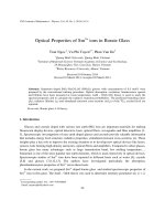
Fig. 11. Schematic representation of the proposed mechanism for the PL excitation,
the energy transfer and the PL in ZnS:Mn nanoclusters.
313
case the Mn2+ emission intensity kept constant in the temperature
range of 10–80 K, was somewhat increased in the range of 80–
140 K and then kept again constant in the range of 140–270 K
(Fig. 10(b)). The intensity ratio of the orange and the blue peaks
IO/IB shown in the inset of Fig. 10(b) remarkably increases when
the temperature is increased.
Based on the energy schema depicted in Fig. 11, the observed
photoluminescent behaviour of the Mn-doped ZnS nanoclusters
can be interpreted. On the one hand, the Mn2+ ion-related PL can
be excited at energies corresponding to the Mn2+ ion own excited
states. On the other hand, when the Mn-doped ZnS nanoclusters
are excited by UV light (interband transitions), electrons in the valence band of the ZnS host absorb the photon energy and transfer
to the conduction band, generating free electrons in the conduction
band and free holes in the valence band. At low temperatures most
of these photogenerated electrons and holes are trapped on the
DAP states (transition (1)) and then recombine via these states,
exhibiting the dominant blue emission. A number of the photogenerated holes in the valence band are trapped by Mn2+ ions which
then become Mn3+ ions. Subsequent trapping of a number of the
photogenerated electrons in the conduction band results in Mn2+
ions in an excited state (Mn2+)* (transition (2)) and the following
transitions of Mn ions from the excited state (Mn2+)* to the basic
state Mn2+ accompany the orange emission. This process can be
described by the following equations [36]:
þ
Mn2þ þ h ðVBÞ ! Mn3þ
Mn
3þ
þ eÀ ðCBÞ ! ðMn2þ ÞÃ
2þ Ã
2þ
ðMn Þ ! Mn
ð6Þ
þ hmMn
With increasing temperature, electrons and holes on the DAPs
with smaller distance r are thermally released into the bands. A
part of the holes and the electrons just released from the DAPs
are retrapped by Mn2+ ions (transition (3) in Fig. 11), emitting
the orange photon. The result is that the blue emission strongly
quenches, on the contrary, the intensity of the Mn2+ emission not
only does not decrease, but even can somewhat increase with
increasing temperature as observed in our ZnS:Mn samples. It is
noted that in our ZnS:Mn samples, the Mn2+ ion is not excited
via the DAPs, because if this occurs, the intensity of both the blue
and the orange emissions will decrease with increasing temperature, which is not consistent with our experimental observation.
4. Conclusion
Undoped and Mn-doped ZnS nanoclusters with 0.5, 1, 3, 10 and
20 at.% Mn dopant have been prepared by a hydrothermal approach. All the prepared ZnS nanoclusters possessed cubic sphalerite crystal structure with lattice constant a = 5.408 ± 0.011 Å. The
absorption bands corresponding to the transitions from the basic
state to the excited states of the Mn2+ ion were observed in both
the reflection, absorption spectra and the PLE spectra. The PL spectra of Mn-doped ZnS nanoclusters exhibited both the blue defectrelated emission and the orange Mn2+ ion-related emission. Furthermore, the blue emission was dominant at low temperatures;
meanwhile the orange emission was dominant at room temperature. The Mn2+ emission intensity showed a maximum when the
Mn doping content was 1 at.%. The Mn2+ ion-related PL can be excited both at energies near the band-edge of ZnS host (the UV region) and at energies corresponding to the Mn2+ ion own excited
states (the visible region). When the Mn-doped ZnS nanoclusters
are excited by the interband transitions, the energy transfer from
ZnS host to Mn2+ ion is carried out by the photogenerated carriers
in the bands or the carriers thermally released from the DAP states
into the bands.
314
T.T.Q. Hoa et al. / Optical Materials 33 (2011) 308–314
Acknowledgement
This work is financially supported by Ministry of Science and
Technology of Viet Nam (Contract No. 38/355/2008/HD-NDT for
Task of Protocol with Israel and Project No 103.02.51.09 from
NAFOSTED). The authors thank Kelvin Nanocharacterisation Centre, University of Glasgow, UK and Dr. Sam McFazdean for HRTEM
measurement support. The authors also thank the members of
Prof. Nozue’s group, Osaka University for the diffuse reflection
measurements.
References
[1] R.N. Bhargava, D. Gallagher, X. Hong, A. Nurmikko, Phys. Rev. Lett. 72 (1994)
416.
[2] R.N. Bhargava, D. Gallagher, T. Welker, J. Luminescence 60–61 (1994) 275.
[3] L. Levy, N. Feltin, D. Ingert, M.P. Pileni, Langmuir 15 (1999) 3386.
[4] G. Counio, T. Gacoin, J.P. Boilot, J. Phys. Chem. B 102 (1998) 5257.
[5] M.J. Tanaka, J. Luminescence 100 (2002) 163.
[6] M. Morita, D. Rau, H. Fujii, Y. Minami, S. Murakami, M. Baba, M. Yoshita, H.
Akiyama, J. Luminescence 87–89 (2000) 478.
[7] P.V. Radovanovic, N.S. Norberg, K.E. McNally, D.R. Gamelin, J. Am. Chem. Soc.
124 (2002) 15192.
[8] D.J. Norris, Nan Yao, F.T. Charnock, T.A. Kennedy, Nano Letters 1 (2001) 3.
[9] L. Sangwook, S. Daegwon, L. Jongwon, K. Seontai, I.Y. Parka, W. Mi-Sook, Mater.
Sci. Eng. B 103 (2003) 241.
[10] K. Jayanthi, S. Chawla, H. Chander, D. Haranath, Cryst. Res. Technol. 42 (2007)
976.
[11] Ping Yang, Mengkai Lu, Dong Xu, Duolong Yuan, Guangjun Zhou, Chem. Phys.
Lett. 336 (2001) 76.
[12] G. Hajisalem, M. Maradi, N. Taghavinia, M. Houshiar, Nanotechnology 20
(2009) 095706.
[13] Subhajit Biswas, Soumitra Kar, Nanotechnology 19 (2008) 045710.
[14] R. Maity, K.K. Chattopadhyay, Nanotechnology 15 (2004) 812.
[15] H.C. Warad, S.C. Ghosh, B. Hemtanon, C. Thanachayanont, J. Dutta, Sci. Technol.
Adv. Mater. 6 (2005) 296.
[16] Sameer Sapra, J. Nanda, A. Anand, S.V. Bhat, D.D. Sarma, J. Nanosci. Nanotech. 3
(2003) 392.
[17] B. Bhattacharjee, D. Ganguli, K. Iakoubovskii, A. Stesmans, S. Chaudhuri, Bull.
Mater. Sci. 25 (2002) 175.
[18] Lixin Cao, Jiahua Zhang, Shanling Ren, Shihua Huang, Appl. Phys. Lett. 80
(2002) 4300.
[19] M. Tanaka, J. Qi, Y. Masumoto, J. Luminescence 87–89 (2000) 472.
[20] W. Chen, F. Su, G. Li, A.G. Joly, J.O. Malm, J.O. Bovin, J. Appl. Phys. 92 (2002)
1950.
[21] Shigeo Shionoya, William M. Yen (Eds.), Phosphor Handbook edited under the
Auspices of Phospor Research Society, CRC Press, Boca Raton Boston London
Newyork Washington D.C., 1999. pp. 763.
[22] B.E. Warren, X-ray Diffraction Dover publications, Inc, New York, 1990. p. 253.
[23] T. Kushida, Y. Tanaka, Y. Oka, Solid State Commun. 14 (1974) 617.
[24] Sameer Sapra, N. Shanthi, D.D. Sarma, Phys. Rev. B 66 (2002) 205202.
[25] J.I. Pankove, Optical Processes in Semiconductors, Prentice-Hall Inc., USA,
1971. 36.
[26] B.Y. Geng, X.W. Liu, Q.B. Du, X.W. Wei, L.D. Zhang, Appl. Phys. Lett. 88 (2006)
163104.
[27] L. Levy, J.F. Hochepied, M.P. Pileni, J. Phys. Chem. 100 (1996) 18322.
[28] S. Kar, S. Chaudhuri, J. Phys. Chem. B 109 (2005) 3298.
[29] S. Oda, H. Kukimoto, J. Luminescence 18–19 (1979) 829.
[30] J. Leeb, V. Gebhardt, G. Muller, D. Haarer, D. Su, M. Giersig, McMahon, L.
Spanhel, J. Phys. Chem. B 103 (1999) 7839.
[31] S. Kar, S. Biswas, S. Chaudhuri, P.M.G. Nambissan, Nanotechnology 18 (2007)
220606.
[32] Qi Xiao, Chong Xiao, Opt. Mater. 31 (2008) 455.
[33] K. Sooklal, B.S. Cullum, S.M. Angel, C.J. Murphy, J. Phys. Chem. 100 (1996) 4551.
[34] D.G. Thomas, M. Gershenzon, F.A. Trumbore, Phys. Rev. 133 (1964) A269.
[35] M. Tanaka, Y. Masumoto, Chem. Phys. Lett. 324 (2000) 249.
[36] J.F. Suyver, S.F. Wuister, J.J. Kelly, A. Meijerink, Nano Lett. 1 (2001) 429.