DSpace at VNU: ANALYSIS OF HIGH-SPEED RAIL ACCOUNTING FOR JUMPING WHEEL PHENOMENON
Bạn đang xem bản rút gọn của tài liệu. Xem và tải ngay bản đầy đủ của tài liệu tại đây (249.09 KB, 12 trang )
2nd Reading
September 18, 2013 16:52 WSPC/0219-8762
196-IJCM
1343007
International Journal of Computational Methods
Vol. 11, No. 3 (2014) 1343007 (12 pages)
c World Scientific Publishing Company
DOI: 10.1142/S021987621343007X
ANALYSIS OF HIGH-SPEED RAIL ACCOUNTING
FOR JUMPING WHEEL PHENOMENON
KOK KENG ANG∗,‡ , JIAN DAI∗,§ , MINH THI TRAN∗,¶
and VAN HAI LUONG†,
Int. J. Comput. Methods 2014.11. Downloaded from www.worldscientific.com
by FUDAN UNIVERSITY on 05/07/15. For personal use only.
∗Department
of Civil and Environmental Engineering
National University of Singapore, Singapore
†Department of Civil Engineering
Ho Chi Minh City University of Technology
HCM City, Vietnam
‡
§
¶
Received 5 March 2012
Accepted 3 July 2012
Published 20 September 2013
In this paper, a computational study using the moving element method (MEM) was
carried out to investigate the dynamic response of a high-speed train–track system.
Results obtained using Hertz contact model and linearized Hertz contact model are
compared and discussed. The dynamic responses of a train travelling across a uniform
foundation and a transition region are also investigated. Parametric study is performed
to understand the effect of various factors on the occurrence and patterns of the jumping
wheel phenomenon such as the variation of foundation stiffness, travelling speed of the
train and the severity of railhead roughness.
Keywords: Moving element method; track transition; wheel–rail interaction; track
irregularity.
1. Introduction
Railway transportation is one of the key modes of travel today. The advancement
in train technology leading to faster and faster trains is without doubt a positive
development, which makes high-speed rail (HSR) system more attractive as an
alternative to other modes of transportation for long distance travel. Due to the
high speed of train moving over the track, the chance of occurrence of the “jumping
wheel” phenomenon is high in particular when the railhead roughness or so-called
“track irregularity” is significant. As the name implies, the phenomenon describes
the situation when there is a momentary loss of contact between the wheel and rail.
It is expected that the response of the train–track system would be significantly
1343007-1
2nd Reading
September 18, 2013 16:52 WSPC/0219-8762
196-IJCM
1343007
Int. J. Comput. Methods 2014.11. Downloaded from www.worldscientific.com
by FUDAN UNIVERSITY on 05/07/15. For personal use only.
K. K. Ang et al.
higher when there is occurrence of such phenomenon. The deterioration rate of the
railway system is also accelerated and the risk of derailment increased. Thus, it is
important to model correctly the dynamic behavior of train–track system accounting for the possible occurrence of the jumping wheel phenomenon.
Another issue that is heightened with the increase in speed of train is the
traveling condition of the train–track system at railway track transitions. Transition regions are places where the stiffness of the foundation experiences an abrupt
change. They are often located at the entrance and exit points of a train tunnel or a
bridge. Such transition regions have been known to cause problems [Esveld (2001);
Lei and Mao (2004); Dimitrovov´
a and Varandas (2009); Lei (2006)]. However, the
response of the train–track system at track transition areas has not been extensively
studied, i.e., the aforementioned research works assumed smooth railhead surface
without any consideration of the initial railhead surface imperfections. It would
therefore be worthwhile to investigate the response of train–track system at track
transitions, in particular, the combined effect of railhead roughness and variation
of foundation stiffness on the occurrence of the jump wheel phenomenon as well as
its patterns.
The objective of this paper is to investigate the response of HSR systems with
a realistic computational model based on the moving element method (MEM). The
train is modeled as a sprung-mass system comprising of car body, bogie and wheelset to account for the effect of moving train load. A linearized contact model is used
to account for the contact between wheel and track but which does not model correctly the jumping wheel phenomenon. A more correct model of the jumping wheel
phenomenon is developed using nonlinear Hertz contact theory. Difference between
the results generated using the two contact models is investigated. Parametric studies are carried out to investigate the effect of existence of track transitions, severity
of railhead roughness and train speeds on the inducement of the occurrence of the
jumping wheel phenomenon.
2. Formulation and Methodology
2.1. Modeling of train–track system
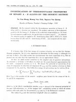
In this paper, the train load is assumed to traverse the railway track at a constant velocity v. The railhead is considered to be not smooth but assumed to have
some imperfections resulting in so-called track irregularity. The moving sprung-mass
model, as shown in Fig. 1, is employed to model the train–track system as a coupled
system composed of the train, railway track and foundation [Ang and Dai (2013)].
The railway track is modeled as an Euler–Bernoulli beam resting on a viscoelastic foundation subject to a moving train load. The governing equation of motion of
the railway beam can be written as [Ang and Dai (2013)]:
EI
∂ 2y
∂y
∂4y
+ k(x)y = Fc δ(x − vt),
+m
¯ 2 + c(x)
4
∂x
∂t
∂t
1343007-2
(1)
2nd Reading
September 18, 2013 16:52 WSPC/0219-8762
196-IJCM
1343007
Analysis of High-Speed Rail
Int. J. Comput. Methods 2014.11. Downloaded from www.worldscientific.com
by FUDAN UNIVERSITY on 05/07/15. For personal use only.
Fig. 1. Moving sprung-mass model.
where EI and m
¯ refer to the flexural rigidity and mass per unit length of the
track, respectively; k(x) and c(x) denote the variation of the vertical stiffness and
damping properties of the foundation along the longitudinal direction of the railway;
y denotes the transversal displacement of the track; x is the spatial coordinate along
the longitudinal direction whose origin is fixed at the initial location of the train; t
the time; δ the Dirac-delta function; and Fc the contact force.
The Hertz contact theory is employed to account for the interaction between
the wheel and rail. According to the theory, the contact surface between the wheel
and rail is an ellipse. The shape of the elliptic contact surface changes according to
the location of the contact indentation. As it is difficult to trace the instantaneous
location of the contact surface, a reasonable assumption can be made such that the
contact surface is always circular [Esveld (2001)], which gives rise to the simplified
form as:
3
KH ∆y 2
0
Fc =
KH =
2
3
E2
∆y ≥ 0
,
∆y < 0
(2a)
Rwheel Rrailprof
,
(1 − υ 2 )2
(2b)
where KH denotes the Hertzian spring constant; Rwheel and Rrailprof denote the
radii of the wheel and railhead, respectively; v the Poisson’s ratio of the material;
∆y the indentation at the contact surface which can be written as:
∆y = yc + yt − u3
(2c)
in which yc and u3 denote the displacements of the track and wheel-set, respectively;
and yt the magnitude of the track irregularity at the contact point. Track irregularity
is a major source of the dynamic excitation. According to the recommendation in
literature [Yang et al. (2004); Nielsen and Igcland (1995)], the track irregularity can
be expressed as:
yt = −at 1 − exp −
x
xc
1343007-3
3
sin
2πx
,
λt
(3a)
2nd Reading
September 18, 2013 16:52 WSPC/0219-8762
196-IJCM
1343007
Int. J. Comput. Methods 2014.11. Downloaded from www.worldscientific.com
by FUDAN UNIVERSITY on 05/07/15. For personal use only.
K. K. Ang et al.
where at and λt denote the amplitude (wave depth) and the wavelength of the
irregularity, respectively; and xc is a constant associated with the condition of the
railhead.
When the train travels far away from its initial position, the exponential term
in Eq. (3a) will soon become negligible; thus for simplicity, the expression for the
vertical track irregularity profile can be written in terms of a sinusoidal function as:
2πx
.
(3b)
yt = −at sin
λt
As the relationship between the contact force and indentation at contact surface is
nonlinear, the computational effort required from adopting such a contact model
in the study of train–track dynamics is generally high. Thus, to avoid the high
computational cost and complexity of the problem, many researchers have adopted
a simplified approach by linearizing the contact force model. The linearized contact
force may be written as:
Fc = KL ∆y,
(4a)
where KL is the linearized Hertzian spring constant evaluated by the relationship
between the force and displacement increments around the static loading condition [Esveld (2001)], in which the reaction force at the contact point equals the
self-weight of the upper structure of the train–track system. Thus, the linearized
Hertzian spring constant may be expressed as:
KL =
3
3E 2 W
Rwheel Rrailprof
.
2(1 − υ 2 )2
(4b)
It is to be noted that the linearized contact model is inappropriate in accounting for
the jumping wheel phenomenon in view that Eq. (4a) indicates that an erroneous
tensile force exists between the wheel and railhead when the phenomenon occurs.
In the treatment of the problem involving a railway transition, it is assumed
that the entire foundation is composed of two adjacent uniform subdomains [Ang
and Dai (2013)]. The stiffness and damping properties of the foundation can be
written as:
k(x) = k1 H(−x + x0 ) + k2 H(x − x0 ),
(5a)
c(x) = c1 H(−x + x0 ) + c2 H(x − x0 ),
(5b)
where x0 denotes the location of the transition point where the two uniform subdomains meet; k1 and c1 refer to the stiffness and damping of the foundation before
and after the transition point, respectively; while k2 and c2 the stiffness and damping of the after the transition point, respectively; and H the Heaviside function.
2.2. Moving element method
Standard finite element method (FEM) usually suffers from the difficulty encountered due to the moving load eventually reaching the boundary of the finite domain,
1343007-4
2nd Reading
September 18, 2013 16:52 WSPC/0219-8762
196-IJCM
1343007
Int. J. Comput. Methods 2014.11. Downloaded from www.worldscientific.com
by FUDAN UNIVERSITY on 05/07/15. For personal use only.
Analysis of High-Speed Rail
rendering the artificial boundary conditions invalid [Ang and Dai (2013)]. In an
attempt to overcome the complication, Krenk et al. [Krenk et al. (1999)] gave a
FE solution to the response of an elastic half-space subject to a moving load in
convected coordinates. Later on, Koh et al. [2003, 2006, 2007] solved different kinds
of problems involving moving loads by adopting the idea of attaching the origin of
the spatial coordinates system to the point of application of the moving load, and
named the numerical method as the MEM. In view that the method had been limited to applications involving horizontally homogeneous foundation, Ang and Dai
[2013] extended the usage of MEM to deal with problems involving horizontally
inhomogeneous foundation.
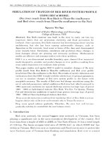
In the MEM, a traveling r-axis is used. The origin of the moving axis is fixed at
the same position of the moving load (see Fig. 2) and is thus traveling at the same
velocity as the load. The relationship between the fixed x and moving r coordinates
is given by
x = r + vt.
(6)
In order to consider the existence of track transitions for train–track dynamic
analysis, the formulation of the equations considering the case in which the vertical stiffness and damping of the foundation is variable is presented below. In
view of Eq. (6), the governing equation for the rail beam given in Eq. (1) may be
rewritten as
∂y
∂ 2y
∂y
∂2y
∂2y
∂4y
+ 2 + c(r)
−v
¯ v 2 2 − 2v
+ k(r)y = Fc δ(r),
EI 4 + m
∂r
∂r
∂r∂t
∂t
∂t
∂r
(7)
where c(r) and k(r) are functions of the moving r-coordinate.
By adopting Galerkin’s approach, the mass, damping, and stiffness matrices of
the moving element can be obtained. After assemblage, the equations of motion for
the train–track model can be written as:
M¨
z + C˙z + Kz = P,
(8)
where z is the global displacement vector of the train–track system; M, C, and K
are the global mass, damping, and stiffness matrices, respectively; and P the global
external load vector.
Fig. 2. Coordinate systems for moving load problem.
1343007-5
2nd Reading
September 18, 2013 16:52 WSPC/0219-8762
196-IJCM
1343007
K. K. Ang et al.
The computational procedure including multiple phases for treating problems
involving a transition region, which is elaborated in [Ang and Dai (2013)], is adopted
in this study.
3. Numerical Results
Int. J. Comput. Methods 2014.11. Downloaded from www.worldscientific.com
by FUDAN UNIVERSITY on 05/07/15. For personal use only.
The effect of various combinations of parameters, including parameters relating to
track transition, on inducing the occurrence of the jumping wheel phenomenon is
investigated. The difference between results obtained using the Hertz contact model
and the linearized contact model is analyzed and discussed.
3.1. Uniform foundation
In this numerical case study, the MEM model comprises of a truncated railway
track of 60 m length uniformly discretized into 600 moving FEs. Newmark’s constant
acceleration method is applied to solve the equations using a time-step of 0.0005 s.
Note that this configuration of the MEM mesh and time-step size have been decided
based on the outcome of a convergence study. It should also be noted that the
testing speeds adopted in the study are far below the critical speed of the system
(subcritical cases) so that the use of transmitting boundary conditions or energy
absorbing layers is not essential [Ang and Dai (2013); Nguyen and Duhamel (2008)].
The parameters for the train model recommended by Koh et al. [2003] are adopted
in the study whereas parameters for the track-foundation model are listed in Table 1.
Unless noted otherwise, all data presented here will be used throughout this paper.
Three typical track irregularities with a wavelength of 1 m and ranging from “near
smooth” to severe condition are used to investigate its effect on the occurrence of
the jumping wheel phenomenon. The amplitudes of the track irregularities are given
in Table 2.
Results obtained from the MEM analyses are presented in Table 3, which shows
the occurrence or nonoccurrence of the jumping wheel phenomenon for various
Table 1. Parameters for track-foundation model.
Parameter
Flexural rigidity
Track section
Value
Parameter
Value
6.12 × 10⁶ Nm2
UIC 60 (60 E1)
Stiffness of foundation
Damping ratio
1 × 10⁷ N/m2
0.1
Table 2. Track irregularities.
Severity
Amplitude (mm)
Near smooth
Moderate
Severe
1343007-6
0.05
2
4
2nd Reading
September 18, 2013 16:52 WSPC/0219-8762
196-IJCM
1343007
Analysis of High-Speed Rail
Table 3. Occurrence of jumping wheel phenomenon.
Severity
Int. J. Comput. Methods 2014.11. Downloaded from www.worldscientific.com
by FUDAN UNIVERSITY on 05/07/15. For personal use only.
Near smooth
Moderate
Severe
Speed (m/s)
50
70
90
0
0
S
0
0
S
0
S
S
speeds of train and severity of track irregularity. A zero value implies that no jumping wheel phenomenon took place and a “S” entry indicates that the phenomenon
occurred and is sustained throughout the journey. It is found that track irregularity
and speed of train are two key factors affecting the occurrence of the jumping wheel
phenomenon. Jumping wheel is noted to easily occur when the track irregularity is
considered severe. For less severe condition, there is also a good possibility for the
occurrence of the phenomenon when the speed of train is high. As to be expected,
when the track is nearly smooth, jumping wheel is unlikely to occur even at very
high train speed. Thus, the simpler linearized contact model without allowing for
the possible loss of contact between the wheel and rail is not suitable to account
for the wheel–rail interaction when the two factors are not considered to be small
enough.
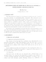
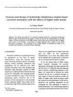
Figures 3 and 4 show, respectively, the displacement profiles of the rail at contact
point for near smooth and severe track irregularities when the speed of train is
90 m/s (324 km/h). In the figures, a nondimensional variable N is introduced as:
N=
vt
.
λt
Fig. 3. Displacement profile of rail at contact point (near smooth track irregularity).
1343007-7
(9)
2nd Reading
September 18, 2013 16:52 WSPC/0219-8762
196-IJCM
1343007
Int. J. Comput. Methods 2014.11. Downloaded from www.worldscientific.com
by FUDAN UNIVERSITY on 05/07/15. For personal use only.
K. K. Ang et al.
Fig. 4. Displacement profile of rail at contact point (severe track irregularity).
As can be seen from Fig. 3, results obtained using the nonlinear Hertz and linearized contact models are found to be comparable with each other when there is
no occurrence of jumping wheel phenomenon. However, as can be seen from Fig. 4,
the difference between the two contact models is large when there is an occurrence
of the jumping wheel phenomenon due to the incapability of the linearized contact
model in simulating such a phenomenon.
3.2. Track transition
The effect of track transition on the dynamic response of HSR system is next
investigated. The parameter measuring the “magnitude” of the transition effect
is described by the ratio of the foundation stiffness after and before the transition
point. A computational study to investigate the combined effects of track irregularity and foundation stiffness ratio on the dynamic behavior of HSR system is carried
out. The train is assumed to be travelling at a constant velocity of 90 m/s. Table 4
shows the parameters of the track irregularities adopted in this study. A same track
Table 4. Track irregularities.
Track irregularity
Irregularity
Irregularity
Irregularity
Irregularity
Amplitude (mm)
1
2
3
4
0.05
0.10
0.30
0.50
1343007-8
2nd Reading
September 18, 2013 16:52 WSPC/0219-8762
196-IJCM
1343007
Int. J. Comput. Methods 2014.11. Downloaded from www.worldscientific.com
by FUDAN UNIVERSITY on 05/07/15. For personal use only.
Analysis of High-Speed Rail
irregularity of wavelength of 1 m is considered for all cases. Note that “Irregularity 1” pertains to that of a near smooth track. The degree of track irregularity
increases from “Irregularity 1” to “Irregularity 4”. All these track conditions may
be considered to be not as severe than a moderately corrugated track. For such
track irregularity conditions and same properties of track and foundation listed in
Table 4, no jumping wheel phenomenon is expected to occur when the foundation is uniform (n = 1). The aim of this investigation is therefore to determine
what degree of track transition will induce the occurrence of the jumping wheel
phenomenon.
Table 5 presents the results showing the occurrence or nonoccurrence of the
jumping wheel phenomenon for various track irregularity conditions and foundation stiffness ratios, n. The numerical value listed in the table denotes the number
of times the wheel jumps in the vicinity of the transition point. No jumping wheel
phenomenon is found to occur for the near smooth track for all values of n considered. There is also no occurrence for all track conditions considered when the
degree of track transition is not large (n < 4). However, jumping wheel is found to
occur occasionally for certain combinations of track condition and degree of track
transition. Also, when the degrees of track transition or track irregularity increase,
the jumping wheel phenomenon is observed to occur and sustained after the train
passes the transition point.
Figure 5 shows the dynamic amplification factor (DAF) in contact force in the
vicinity of the transition point. The DAF is computed by taking the ratio of the
maximum dynamic contact force to the combined self-weights of car body, bogie,
and wheel-set. In all cases, it is found that increasing stiffness ratio has the effect of
increasing the maximum contact force, which agrees with one of the findings from
[Ang and Dai (2013)]. It is also observed that the effect of stiffness ratio within the
range of 8–16 tends to have smaller effect on the increase in DAF when compared
with that within the range of 4–8, which implies that the stiffness ratio smaller
than 8 tends to have more impact on the responses of the HSR system. Figures 6
and 7 present the contact force distributions along the railhead in the vicinity of
the transition point for various track conditions with n = 4 and various foundation
stiffness ratios for track “Irregularity 2”, respectively. Note that x − x0 = 0 refers
to the transition point. As can be seen from these figures, the maximum contact
Table 5. Occurrence of jumping wheel phenomenon.
n
Irregularity
Irregularity
Irregularity
Irregularity
Irregularity
1
2
3
4
1
2
4
8
16
0
0
0
0
0
0
0
0
0
0
0
1
0
2
S
S
0
S
S
S
1343007-9
2nd Reading
September 18, 2013 16:52 WSPC/0219-8762
196-IJCM
1343007
Int. J. Comput. Methods 2014.11. Downloaded from www.worldscientific.com
by FUDAN UNIVERSITY on 05/07/15. For personal use only.
K. K. Ang et al.
Fig. 5. Effect of stiffness ratio and track irregularity on DAF.
Fig. 6. Effect of track irregularity on contact force.
force occurs after the wheel passes the transition point. It is also observed from
Fig. 6 that when n = 4, the contact force attains a zero value momentarily at a
location about 2.1 m after passing the transition point indicating that the wheel
jumps once at this location. For a large stiffness ratio of 8 or 16, the jumping wheel
phenomenon is found to occur after the wheel passes the transition point and is
observed to be sustained as the train travels over the second foundation, resulting
in a sharp increase in the DAF in contact force as shown in Fig. 5. It can be seen
from Fig. 7 that the phenomenon occurred twice due to the existence of a track
1343007-10
2nd Reading
September 18, 2013 16:52 WSPC/0219-8762
196-IJCM
1343007
Int. J. Comput. Methods 2014.11. Downloaded from www.worldscientific.com
by FUDAN UNIVERSITY on 05/07/15. For personal use only.
Analysis of High-Speed Rail
Fig. 7. Effect of foundation stiffness ratio on contact force.
transition of stiffness ratio 8. For a larger stiffness ratio of 16, the phenomenon is
induced and sustained after the train travelled past the transition point.
4. Conclusions
In this paper, a computational study on the dynamic response of HSR system
using the MEM is carried out. Both the situations of a uniform foundation and a
transition region are considered. The proposed computational model adopts Hertz
contact theory to account for the wheel–rail interaction. The results obtained using
Hertz contact model and linearized contact model are compared and discussed. The
occurrence of the jumping wheel phenomenon is accounted for and examined.
In the parametric study on the occurrence of the jumping wheel phenomenon,
it was found that the speed of the travelling train and the severity of track irregularity are key factors affecting the occurrence of this phenomenon. The jumping
wheel phenomenon generally does not occur when either the speed of the train is
relatively low or the track surface nearly smooth. As to be expected, the dynamic
response of the train–track system is found to be significantly higher when there is
an occurrence of jumping wheel. This has important implication on the track maintenance program. It is critical that track maintenance is properly exercised and/or
train operational speed be moderated to avoid any occurrence of the jumping wheel
phenomenon, especially for old tracks where track corrugation is likely to be severe.
Also, it is critical that the nonlinear Hertz contact model be adopted to model correctly the wheel–rail interaction, especially when there is strong possibility of the
occurrence of the jumping wheel phenomenon.
In the response study of the train–track system involving railway track transitions, it is found that increasing foundation stiffness ratio has the effect of increasing
1343007-11
2nd Reading
September 18, 2013 16:52 WSPC/0219-8762
196-IJCM
1343007
K. K. Ang et al.
Int. J. Comput. Methods 2014.11. Downloaded from www.worldscientific.com
by FUDAN UNIVERSITY on 05/07/15. For personal use only.
the maximum contact force. In general, it is found that large change in foundation
stiffness and higher degree of track irregularity tends to induce the occurrence of the
jumping wheel phenomenon. Thus, no such phenomenon is observed to occur for
near smooth railhead condition for all foundation stiffness ratios considered. Similarly, the phenomenon does not occur for smaller values of foundation stiffness ratios
even for track irregularity considered moderate. The jumping wheel phenomenon
is triggered under certain combinations of severity of track irregularity and degree
of track transition. When both parameters are large enough, the phenomenon is
observed to occur sporadically or repeatedly after the train passes the transition
point.
References
Ang, K. K. and Dai, J. [2013] “Response analysis of high-speed rail system accounting for
abrupt change of foundation stiffness,” J. Sound Vib. 332, 2954–2970.
Dimitrovov´
a, Z. and Varandas, J. N. [2009] “Critical velocity of a load moving on a beam
with a sudden change of foundation stiffness: Applications to high-speed trains,” Comput. Struct. 87, 1224–1232.
Esveld, C. [2001] Modern Railway Track, 2nd edn. (MRT Productions, Duisburg).
Koh, C. G., Chiew, G. H. and Lim, C. C. [2007] “A numerical method for moving load on
continuum,” J. Sound Vib. 300, 126–138.
Koh, C. G., Ong, J. S. Y., Chua, D. K. H. and Feng, J. [2003] “Moving element for
train–track dynamics,” Int. J. Numer. Meth. Eng. 56, 1549–1567.
Koh, C. G., Sze, P. P. and Deng, T. T. [2006] “Numerical and analytical methods for
in-plane dynamic response of annular disk,” Int. J. Solids Struct. 43, 112–131.
Krenk, S., Kellezi, L., Nielsen, S. R. K. and Kirkegaard, P. H. [1999] “Finite elements
and transmitting boundary conditions for moving loads,” Proc. 4th European Conf.
Structural Dynamics, Eurodyn’ 99, Praha, June 7–1, Vol. 1, pp. 447–452.
Lei, X. Y. [2006] “Effects of abrupt changes in track foundation stiffness on track vibration
under moving loads,” J. Vib. Eng. 19(2), 195–199.
Lei, X. Y. and Mao, L. J. [2004] “Dynamic response analysis of vehicle and track coupled
system on track transition of conventional high speed railway,” J. Sound Vib. 271,
1133–1146.
Nguyen, V.-H. and Duhamel, D. [2008] “Finite element procedures for nonlinear structures
in moving coordinates. Part II: Infinite beam under moving harmonic loads,” Comput.
Struct. 86, 2056–2063.
Nielsen, J. C. O. and Igeland, A. [1995] “Vertical dynamic interaction between train and
track-influence of wheel and track imperfections,” J. Sound Vib. 187(5), 825–839.
Yang, Y. B., Yau, J. D. and Wu, Y. S. [2004] Vehicle-Bridge Interaction Dynamics: With
Applications to High-Speed Railways (World Scientific, Singapore).
1343007-12