DSpace at VNU: Effects of Carbon Nanotube Dispersion Methods on the Radar Absorbing Properties of MWCNT Epoxy Nanocomposites
Bạn đang xem bản rút gọn của tài liệu. Xem và tải ngay bản đầy đủ của tài liệu tại đây (1.16 MB, 8 trang )
Macromolecular Research, Vol. 22, No. 11, pp 1221-1228 (2014)
DOI 10.1007/s13233-014-2169-8
www.springer.com/13233
pISSN 1598-5032 eISSN 2092-7673
Effects of Carbon Nanotube Dispersion Methods on the Radar Absorbing
Properties of MWCNT/Epoxy Nanocomposites
Bien Dong Che1, Le-Thu T. Nguyen*,2, Bao Quoc Nguyen1, Ha Tran Nguyen2,
Thang Van Le2, and Nieu Huu Nguyen*,1
1
National Key Laboratory of Polymer and Composite Materials- Ho Chi Minh City University of Technology,
Vietnam National University, 268 Ly Thuong Kiet, District 10, Ho Chi Minh City, Vietnam.
2
Faculty of Materials Technology and Materials Technology Key Laboratory (Mtlab),
Ho Chi Minh City University of Technology, Vietnam National University,
268 Ly Thuong Kiet, District 10, Ho Chi Minh City, Vietnam
Received April 16, 2014; Revised July 29, 2014; Accepted July 31, 2014
Abstract: Radar absorbing materials (RAMs) for practical applications are expected not only to have strong microwave absorption and a wide absorption bandwidth, but also to be lightweight, to have a fine thickness and acceptable
structural performance, as well as being cost-effective. Although the dispersion of carbon-nanofillers in polymer
matrices is a key factor determining the microwave absorbing properties of the composites, there have few studies
on these effects. To our knowledge, to date, the realization of pristine multi-walled carbon nanotube (MWCNT)/polymer
composites as RAMs in industrial production has been restricted, due to high CNT contents or large composite thicknesses. Thus, in this work, two MWCNT dispersion processing methods, a solution process with surfactant-aid and
a ball-milling dispersion, were investigated to fabricate pristine MWCNT/epoxy nanocomposites. The effects of the
different dispersion processes, CNT loading, and composite thickness on CNT dispersion in the matrix, were observed
by TEM, and the electrical conductivity and X-band absorbing performance of the composites were assessed. The
use of an ionic surfactant to aid the dispersion of CNTs in solution resulted in the best RAMs, with a good compromise among effective X-band absorption, small composite thickness, and very low CNT content. The ball-milling
method also resulted in materials with a low CNT content and microwave absorbing performance acceptable for
industrial applications. Moreover, it offers a very simple and efficient route suitable for low-cost, mass production
of RAMs. The results showed that by facile approaches of dispersing pristine commercial MWCNTs in an epoxy
resin matrix, composites of only 2-3 mm thickness and as little as 0.25-0.5 wt% CNT loading could be obtained,
with a relatively wide X-band operating bandwidth and maximum absorptions exceeding 18-25 dB.
Keywords: radar absorbing materials (RAMs), carbon nanotubes, polymer composites, nanocomposites.
Introduction
prompted extensive studies in the last decade. Numerous
composites based on carbon black, graphenes, fullerences,
graphites, carbon nanotubes and nanofibers as radar absorbing
materials (RAMs) have been reported.1,2 In this scenario,
carbon nanotubes (CNTs) have demonstrated a potential as
great conductive nanofillers with outstanding electrical properties, such as ultra-low percolation thresholds for both electrical conductivity and microwave absorbance,3,4 ascribed to
the high aspect ratio between 100 and 1000.
An effective RAM needs to achieve a reflection loss value
in the X-band frequency region above 10 dB (more than 90%
microwave energy absorbed). Thus, a wealth of experimental efforts has been devoted to enhance the microwave absorption efficiency of CNT/polymer composites through tailoring
the geometry and composition of CNT fillers and host polymers, as well as CNT content, composite thickness, processing
The research in the area of carbon nanostructure-filled
polymer nanocomposites as microwave absorbers both in
civil and military applications has gained remarkable attention, owing to their ability to tailor the electrical and magnetic properties at relatively low nanofiller concentrations,
as well as their light weight, excellent thermal stability and
high mechanical properties. In particular, the demand for
the operation of radar absorbing materials in the 8-12 GHz
region (X-band) with enhanced shielding and microwave
absorption effectiveness for applications in military communication satellites, Doppler and weather radars, television satellite transmitters and telephone microwave relay systems, has
*Corresponding Author. E-mail:
The Polymer Society of Korea
1221
B. D. Che et al.
technique and the dispersion of CNTs in the polymer matrix.1
To increase the reflection loss, which was less than 2 dB
in the range of 2-18 GHz, of a multi-walled CNT (MWCNT)/
epoxy nanocomposite with 20 wt% CNT loading and 1.2 mm
thickness, Che et al.5 investigated the use of Fe-filled CNTs.
By filling crystalline -Fe into the carbon shells of CNTs,
the reflection loss of Fe-filled CNT/epoxy composites was
enhanced substantially up to 17-25 dB. Other effective RAMs
with high CNT loadings of 15 to 30 wt% have also been obtained
by filling MWCNTs with Fe,6,7 Fe3C,7 cobalt,8 Er2O3,9 and
Sm2O3,10 or by coating the MWCNT structure with TiO2 or
Nickel.11-13
On the other hand, without modifying CNTs, numerous
studies employing different polymer hosts and CNT-resin
mixing methods have been conducted to gain desirable
microwave absorption performance of pristine CNT/polymer
nanocomposites via the use of either high CNT contents or
large matching thicknesses. Fan et al.14 applied twin-screw
extrusion and sand-milling to prepare nanocomposites of
MWCNTs and several polymer matrices such as PET, PP,
PE and varnish. CNT/PET and CNT/varnish composites with
4 and 8 wt% of CNTs and thicknesses of 2 and 1 mm were
obtained, showing reflection loss peaks at 7.6 and 15.3 GHz
with maximum values of 17.61 and 24.27 dB, respectively.
Liu et al.15 prepared 2 mm thick CNT/polyurethane nanocomposites with 0-25 wt% of single-walled CNTs (SWCNTs)
through solution mixing in dimethylformamide followed by
slow drying. 5 wt% was the optimal CNT loading giving a
maximum absorbing value of 22 dB at 8.8 GHz. In other
studies on MWCNT/paraffin composites at a substantially
high CNT loading of 20 wt%, the maximum absorbing values of the pristine CNT composites reported by Lin et al.6,8
did not reach the acceptable limit above 10 dB, whereas
those by Zhang et al.9,10 achieved maximum peaks of 22 dB
in the X-band region. Despite the use of the same source of
MWCNTs in these works, such different absorbing performance might originate from the difference in CNT dispersion
quality. Helical and worm-like MWCNT/paraffin composites with 30 wt% CNTs and 2.8-3 mm thicknesses have also
been reported, exhibiting maximum reflection loss values of
about 26 dB at 7-8 GHz.16 Twin carbon nanocoils were synthesized and their nanocomposites in paraffin were prepared,
obtaining maximum reflection loss values above 10 dB in
the X-band region at carbon nanocoil contents of 15-22 wt%
and matching thicknesses of 3-3.5 mm.17 Lately, Bhattacharya et al.12 prepared a 2 mm thick unmodified MWCNT/
polyurethane nanocomposite at a 30 wt% CNT loading through
solution blending using mechanical stirring, with the maximum reflection loss of 16.03 dB at 10.99 GHz. Using ultrasonication and ultraturax mixing to disperse CNTs in epoxy
resins, MWCNT/epoxy nanocomposites with CNT loadings, matching thicknesses and maximum reflection loss of
0.5 wt%, 9 mm, 25 dB at 11 GHz as well as 5 wt%, 3 mm,
18 dB at 8 GHz, respectively, have been reported.18,19
1222
However, either the high CNT loadings of 4-30 wt% or
large composite thicknesses reported so far for pristine CNT/
polymer composite RAMs can be drawbacks limiting their
commercial applications. In this sense, light weight, thin
composites are preferred. Moreover, it is known by the literature that the elastic modulus of MWCNT/epoxy increases with
CNT content.20,21 However, the fracture strength decreases with
increasing CNT concentration.20,22 The strain-at-break of
MWCNT/polypropylene composites has been reported to
decrease significantly at 2 and 5 wt% CNT loadings.21
Hence, addition of more than several weight percents of CNTs
may not maintain the structural mechanical integrity of composites.
A good dispersion of CNTs in composites is a crucial factor for optimization of their performance. Various processing techniques to enhance the dispersion of CNTs have been
suggested, such as melt mixing using extruders and solvent
processing by means of centrifugation, ultrasonication and
surfactant treatment, as well as chemical modification of
CNTs.23-28 While a majority of works have studied the effects of
dispersion methods on the mechanical, thermal and electrical properties of carbon filler/polymer composites,21,23,24,28-37
literature on the dependence of microwave absorption characteristics on the dispersion conditions is sparse.38 Nanni et
al.38 observed the influence of the organic solvent removal
conditions, i.e. via evaporation or filtration after dispersion
of carbon nanofibers (CNFs) in the epoxy matrix, on the
aggregation of CNFs. This led to different microwave absorbing performance. Optimization of the filler content and matching
thickness resulted in 4 mm thick CNT/epoxy composites with
3-4 wt% CNT contents and maximum absorption peak values of 20-25 dB in the region above X-band, of 14-20 GHz.
In consideration of the key role of CNT dispersion in the
aggregation and agglomeration of CNTs and hence material
electromagnetic characteristics, in this work we studied the
effects of two dispersion methods on the X-band microwave
performance of MWCNT/epoxy nanocomposites. The dispersion processes in solution with the aid of a surfactant and in
bulk via ball-milling were employed for the fabrication of
composites with various CNT loading contents. Epoxy resin
was chosen as the matrix because of its wide practical applications owing to the low cost, resistance to oxidative photodegradation and stability against UV light. An overall investigation
of the influence of fabrication conditions on the microwave
absorption behavior of the composites was conducted, considering two practical important issues, i.e. weight reduction
and optimization of the operating bandwidth and absorption.
A good compromise between the microwave absorption performance, composite mechanical properties and especially costeffectiveness can be a challenge in realizing RAMs in real
applications. Alternatively, studies on hybrid composites of
CNTs and metallic magnetic particles requiring specific inhouse particle synthesis and CNT treatment to enhance microwave absorption properties have been ongoing.1 Despite this, it
Macromol. Res., Vol. 22, No. 11, 2014
Effects of Carbon Nanotube Dispersion Methods on the Radar Absorbing Properties of MWCNT/Epoxy Nanocomposites
is without question that a simple fabrication procedure of
industrial grade MWCNT/polymer composites meeting the
essential criterion of cost-versus-performance can be of particular attraction. Through this work, we demonstrate for the
first time to the best of our knowledge, that by processing
design, effective radar absorbing MWCNT/epoxy nanocomposites with microwave energy absorption in the X-band region
above 90% and maximum absorption peak values above 99%,
could be obtained. This pathway shows many advantages
such as simple and easily upscalable production, very low
CNT loadings (0.25-0.5 wt%), and a small matching thickness
(2 mm).
Experimental
Materials. NanocylTM NC7000 multi-walled carbon nanotube
(MWCNT) material was purchased from Nanocyl S.A., Sambreville, Belgium. According to the manufacturer, they have
an average diameter of 9.5 nm, average length of 1.5 m and
surface area of 250-300 m2/g. Ethanol (99.5%, Chemsol),
sodium dodecyl-benzene sulfonate (NaDDBS, Sigma-Aldrich),
D.E.R.TM 331 epoxy resin (Dow) and triethylenetetramine (TETA,
Dow) were used as purchased.
Preparation of Nanocomposites.
MWCNT/Epoxy Composites via the Solution Dispersion
Method: MWCNT/epoxy nanocomposites containing different CNT contents (0.25, 0.5, 0.75, 1, 1.25, 2, and 4 wt%) and
with thicknesses of 2 and 4 mm were prepared. MWCNTs
were dispersed in ethanol and the mixture was sonicated at
55 oC for 60 min. Then, the epoxy resin was added and the
mixture was subjected to continuous simultaneous mechanical
stirring and ultrasonication at 55 oC for 120 min, followed
by solvent evaporation while maintain mechanical stirring
at 80 oC. Finally, the hardener (TETA) was added and the matrix
was cured under ambient conditions for 24 h before characterization.
MWCNT/Epoxy Composites via the Ball-Milling Method:
MWCNT/epoxy nanocomposites containing different CNT
contents (0.25, 0.5, 0.75, 1, and 1.25 wt%) and with a thickness of 3 mm were prepared. MWCNTs were mixed with
the epoxy resin and the mixture was subjected to ball-milling using a porcelain vertical style ball mill jar (capacity of
1 L) containing one pivot and 0.5 kg of porcelain balls of
10-20 mm diameters. The milling intensity was 300 rpm,
the optimal milling time was 60 min and the weight of each
batch was 300 g. After ball-milling, the hardener (TETA)
was added and the matrix was cured under ambient conditions for 24 h before characterization.
Characterization. The dispersion of MWCNTs in the
cured epoxy matrix was observed by transmission electron
microscopy (TEM, JEM 1400, JEOL, Japan). Measurements
of electrical conductivities of the samples were performed
by a two-probe method using the Keithley Model 2750 multimeter (Keithley Instruments Inc., USA). Microwave absorption
Macromol. Res., Vol. 22, No. 11, 2014
study at the 8-12 GHz band was performed on a two port
vector network analyzer (Anritsu MS2028B), using a
reflection/transmission method.
The reflection loss (RL) of a single-layered electromagnetic absorber is defined as:39
Zin – Z0
RL = 20log10 ---------------Zin + Z0
(1)
j2
r
-------- r r fd
Zin = Z0 ----tanh
r
c
(2)
where Zin is the normalized input impedance at free space
and material interface, Z0 is the characteristic impedance of
free space, r and r are respectively the complex relative
permeability and permittivity of the material, c is the velocity of light, f is the frequency and d is the sample thickness.
The relationship between frequency and thickness can be
interpreted as:1
c
f = --------------2 r d
(3)
where ''r is the imaginary part of relative permeability.
Results and Discussion
MWCNT/Epoxy Nanocomposites via the Solution Dispersion Method.
Influence of CNT Content and Composite Thickness:
Via the solution mixing method for dispersion of CNTs in
the epoxy matrix, combining ultrasonication, mechanical stirring
and the use of ethanol as the dispersed solvent which was
evaporated afterward, composites of NanocylTM NC 7000
MWCNTs and epoxy resin were fabricated. The microwave
absorption, operating frequencies and frequency bandwidth
are known to be dependent on the CNT filler content and
matching thickness.1 Thus, these parameters were varied in
order to optimize the X-band microwave absorption performance.
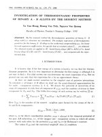
Figure 1 shows the variation of electrical conductivity versus
CNT weight content for composite samples with a thickness
of 2 mm. A low electrical percolation threshold, defined as
a critical filler concentration to achieve a conductivity of 10-8 S/
cm, less than 0.25 wt% is observed. Above the percolation
threshold, increasing CNT content led to increases in electrical conductivity, as a result of the increase of conductive
inclusions making electrical paths inside the matrix. Further
increasing CNT content to 4 wt% significantly enhanced the
conductivity. However, such a high CNT fraction compromised the composite structural integrity. We observed that
the 4 wt% CNT composite was brittle and appeared to crack
upon curing. Thus, to ensure the mechanical properties of
the composites, the addition of MWCNTs in the matrix for
radar-absorbing study was limited to maximum 2 wt%.
The frequency dependence of the microwave absorbing
1223
B. D. Che et al.
Figure 1. Electrical conductivities versus CNT content of MWCNT/
epoxy composites (of 2 mm thickness) prepared via the solution
dispersion method.
characteristics in the X band region of the MWCNT/epoxy
composites prepared via the solution dispersion method is
presented in Figure 2. The effects of variation in both CNT
content and matching thickness were evaluated. It is seen
that, irrespective of the composite thickness, the maximum
absorption increases with CNT content up to 0.75 wt%, above
which it drops significantly. Such phenomenon was explained
by the fact that the material needs to satisfy not only dielectric
loss requirements but also importantly the impedance matching condition (where Zin is close to Z0, eqs. (1) and (2)). The
observation of an optimal CNT content for optimal absorbing ability has been found for other composites of SWCNTs
and MWCNTs.14,15,38 Below the CNT loading of 0.75 wt%,
the increase in microwave absorption with CNT content
could be attributed to the enhancement of dielectric loss tangent, the factor mainly contributing to the attenuation of
microwave energy of carbon nanofiller composites.15,17 At CNT
contents above 0.75 wt%, it was likely that conductivity
prevailed, as a result of short-range electric multipole interactions,14 making the material mostly reflective. Nevertheless, at 2 mm matching thickness, reflection loss peaks did
not lie in the desired frequency range of 8-12 GHz.
As also shown in Figure 2, the microwave absorbing properties were influenced greatly by tuning the nanocomposite
thickness. Below 0.75 wt% CNT loading, increasing the thickness to 4 mm resulted in considerable enhancement of absorbing
performance as well as shifts of maximum reflection loss to
lower frequencies, which can be explained by the relationship between frequency and thickness described in eq. (3).
In addition, it was clearly observed that at this matching
thickness, increasing CNT concentration led to shifts of reflectivity peaks toward lower frequencies. The peak values reached
maxima of -22.2 dB at 11.2 GHz at 0.25 wt% CNT content,
and -32.4 dB at 8.2 GHz at 0.5 wt% CNT. Thus, to achieve
the operating frequency at 8-12 GHz, the optimal CNT content should be below 0.5 wt% at a matching thickness of 4 mm.
Influence of the Use of an Ionic Surfactant: Although
the microwave absorption could be optimized by adjusting
both CNT content and matching thickness, as usually performed in the literature,1 we found that the aid of an ionic
surfactant in the dispersion process had a significant effect
on maximizing absorbing properties of the MWCNT/epoxy
nanocomposites. Apparently, a good dispersion of CNTs inside
the matrix is a critical aspect for achieving good absorbing
materials. Chemical modification methods (for example to
provide amine-functionalized CNTs) for enhancing the dispersion and compatibility of CNTs to the epoxy matrix, have
shown to be detrimental for the overall electrical conductivity.40
Unlike chemical functionalization pathways, the surfactant
treatment has been reported to exhibit little adverse effect on
the electrical properties of CNT/epoxy nanocomposites.31
Thus, sodium dodecyl benzene sulfonate (NaDDBS), one
of ionic surfactants commonly used to reduce the aggregative tendency of CNTs in water,25 was used for the preparation of NanocylTM NC 7000 MWCNT/epoxy composites.
Figure 2. Reflection loss versus frequency at different CNT contents of MWCNT/epoxy composites prepared via the solution dispersion method, with thicknesses of (a) 2 and (b) 4 mm.
1224
Macromol. Res., Vol. 22, No. 11, 2014
Effects of Carbon Nanotube Dispersion Methods on the Radar Absorbing Properties of MWCNT/Epoxy Nanocomposites
Table I. Electrical Conductivities of 2 mm Thick MWCNT/
Epoxy Composites with Various CNT and NaDDBS Contents
MWCNT Content
(wt%)
NaDDBS Content Electrical Conductivity
(wt%)
(S/cm)
0.25
0
1.196×10⁻⁵
0.25
0.05
12.275×10⁻⁵
0.5
0
1.787×10⁻⁵
0.5
0.05
16.979×10⁻⁵
Their X-band absorbing performance was assessed while
maintaining low CNT contents of 0.25 and 0.5 wt% and a
matching thickness of 2 mm. Despite the enhancement of
thermal and mechanical properties of CNT nanocomposites
by a good dispersion of CNTs in the epoxy matrix, the best dispersion conditions resulting in an insulating resin layer between
CNTs may reduce the conductivity.32 Hence, the content of
added NaDDBS was optimized preferably as low as possible, being 0.05 wt%. As shown in Table I, with the use of
NaDDBS, the electrical conductivities of the nanocomposites
increased considerably, approximately by ten times. From
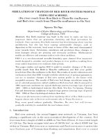
TEM analysis (Figure 3), it appeared that without using NaDDBS
in the dispersion process, CNTs were entangled in ropes. In
this case, it seemed that their intrinsic properties such as
aspect ratio and surface area were less effective in creating
conductive pathways. The addition of NaDDBS allowed the
disassembly of ropes into individual CNT tubes, with a tendency of being aligned in the same directions as a result of
their conglomeration trend. This arises from the adsorption
of surfactants around the nanotubes because of the strong
hydrophobic interactions of NaDDBS alkyl chains as well
as π-stacking interactions of the surfactant benzene groups
with CNTs, besides the hydrogen bonding between sulfonate groups and the epoxy matrix. It is likely that a good dispersion of CNTs exhibiting an anisotropic morphology, with
a certain aspect ratio, of CNT bundles is a control parameter
to constitute a conductive network inside the matrix.
In accordance to the enhanced dispersion and electrical
conductivity of the composites, the use of NaDDBS as a pro-
Figure 3. TEM micrographs of 2 mm thick, 0.25 wt% CNT MWCNT/
epoxy composites prepared via the solution dispersion method
without (a) and with the use of 0.05 wt% NaDDBS (b) (scalebar: 100 nm).
Macromol. Res., Vol. 22, No. 11, 2014
Figure 4. Reflection loss versus frequency of 2 mm thick MWCNT/
epoxy composites prepared via the solution dispersion method,
with 0.25 and 0.5 wt% of CNT contents, with 0 and 0.05 wt% of
NaDDBS.
cessing aid led to drastic increases in microwave absorbing
properties. Without the use of the surfactant, the composites
satisfying both a small matching thickness not more than 2 mm
and a low CNT content not more than 0.5 wt% exhibited little microwave absorption. Similar results have often been
observed for pristine CNT/polymer composites in the literature. As shown in Figure 4, with the use of 0.05 wt% of
NaDDBS and at a matching thickness of 2 mm, the 0.25 wt%
CNT composite shows maximum reflection loss peaks of
17.9 dB at 9.2 GHz and 21.5 dB at 10.6 GHz, while the 0.5 wt%
CNT composite exhibits a reflection loss peak with the maximum value of 26.1 dB at 11.2 GHz. In the contrary to the case
of 4 mm matching thickness and without using a surfactant,
here it appeared that the maximum reflection loss peak shifted to
higher frequency with increasing the CNT content from 0.25 to
0.5 wt%. Interestingly, the bandwidth also increased. Especially, the 0.25 wt% CNT composite exhibited a wide X-band
operating bandwidth (corresponding to reflection loss values above 10 dB) from 8.8 to 11.4 GHz.
MWCNT/Epoxy Nanocomposites via the Dry State Dispersion Method Using Ball-Milling. Ball-milling in the dry
state to disperse CNTs in the epoxy matrix was employed to
prepare MWCNT/epoxy nanocomposites with different CNT
contents. Such a method requires no addition of a solvent
and thereby no solvent evaporation as well as ultrasonication
and mechanical stirring, which is advantageous for mass
production in industrial applications. The ball-milling time
was limited to 60 min, which was optimal for the dispersion
of CNTs without any noticeable decrease of CNT lengths.
As the reflection loss performance generally increases with
matching thickness, the composite thickness was optimized,
in terms of giving both reasonably good reflection loss and
relative thinness, being 3 mm.
From the morphological observation by TEM, as shown
1225
B. D. Che et al.
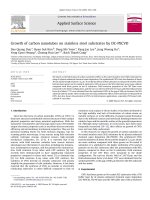
Figure 5. TEM micrographs of 3 mm thick MWCNT/epoxy nanocomposites prepared using the ball-milling method with CNT contents
of 0.125 (a), 0.25 (b), 0.5 (c), 0.75 (d), 1 (e), and 1.25 (f) wt%.
in Figure 5, it is observed that at CNT contents below 1 wt%,
the nanotubes were mostly dis-entangled and dispersed relatively homogeneously in the matrix. There was the co-existence of a small fraction of CNT aggregates as randomly
dispersed entangled clusters of a few hundreds of nanometer
size at CNT contents of 0.5 and 0.75 wt%, which was more
visible at the higher CNT content. At 1 wt% CNT loading,
the CNTs were still quite homogeneously dispersed, despite
that they tended to conglomerate as a result of their dense
coverage in the matrix. Further increasing CNT content to
1.25 wt% led to non-uniform distribution of entangled CNT
bundles.
As shown in Figure 6, according to the increased coverage
of CNTs in the matrix, the electrical conductivity increases
greatly with CNT content owing to the formation of denser
conductive networks. Above 1 wt% CNT loading, the electrical
conductivity increased inconsiderably due to the uneven spreading of CNTs across the matrix.
A high CNT content giving a high electrical conductivity
is not necessary to be optimal for microwave absorbing
properties. As shown in Figure 7, the X-band absorption of
the composites prepared via the ball-milling method shows
a similar trend to that of the composites prepared via the
solution dispersion method. For CNT contents between
1226
Figure 6. Electrical conductivities versus CNT content of 3 mm
thick MWCNT/epoxy composites prepared via the ball-milling
method.
0.25 and 0.75 wt%, microwave absorption above 10 dB was
obtained, with the maximum reflection loss peaks in the Xband region shifting to lower frequencies with increasing
CNT content. The 0.25 wt% CNT composite showed maximum reflection loss peaks of 16.5 dB at 10.3 GHz and 18.4
Macromol. Res., Vol. 22, No. 11, 2014
Effects of Carbon Nanotube Dispersion Methods on the Radar Absorbing Properties of MWCNT/Epoxy Nanocomposites
frequency and CNT content. In summary, composites of thicknesses of 2-3 mm prepared using both dispersion methods,
i.e. in solution with the aid of a surfactant and through ballmilling, exhibited optimal X-band microwave absorbing
performance at only 0.25 wt% CNT, with relatively wide
working bandwidths. The surfactant-aiding solution dispersion method produced RAMs with slightly better reflection
loss values as well as higher electrical conductivities for similar
CNT contents, although at a smaller matching thickness.
This is ascribed to better CNT dispersion in the epoxy matrix.
Nevertheless, the ball-milling dispersion method still offers
good RAMs for industrial applications and is a facile processing route with elimination of the steps of ultrasonication
and solvent evaporation.
Figure 7. Reflection loss versus frequency of 3 mm thick MWCNT/
epoxy composites with different CNT contents prepared via the
ball-milling method.
dB at 8.8 GHz, while the 0.5 wt% CNT composite exhibited
maximum reflection loss peaks of 14.5 dB at 9.8 GHz and
16.7 dB at 8.1 GHz. On the other hand, CNT contents below
0.5 wt% and above 0.75 wt% led to ineffective microwave
absorption performance.
A comparison of the X-band microwave absorption properties of MWCNT/epoxy composites prepared using the
ball-milling, solution mixing and surfactant-aiding solution
mixing dispersion methods, with 0.25 and 0.5 wt% CNT
contents is shown in Figure 8. It is clearly observed that the
dispersion method can change drastically the reflection loss
characteristics, not only the reflection peak values and bandwidth, but also the correlation between the absorption peak
Conclusions
In this paper, two MWCNT dispersion processes, a solution process with surfactant-aid and room-temperature ballmilling, were employed to prepare industrial grade-MWCNT/
epoxy nanocomposites as radar absorbing materials. The effects
of these methods as well as CNT content, matching thickness
and the addition of a surfactant on the electrical conductivity
and X-band absorbing performance of the composites were
investigated. Both methods resulted in MWCNT/epoxy
composite RAMs compromising both very low CNT contents
of only 0.25-0.5 wt% and small matching thicknesses of 2-3
mm as well as good absorbing properties. At only 0.25 wt%
CNT addition, they showed microwave absorption values
above 10 dB in wide frequency ranges of 8.8-11.4 and 8.5-11
GHz, with maximum reflection loss peaks between 16.5 and
21.5 dB. These values are considerably better than the absorbing performance of pristine CNT/polymer composites with
similar or lower thicknesses and CNT loadings below 5 wt%
reported so far. The results showed that such facile processing routes, not requiring any in-house synthesis or chemical
modification of the CNT structure, are of particular attraction for industrial production of cost-effective and lightweight radar absorbers.
Acknowledgments. The authors thank the Vietnam Ministry of Science and Technology for funding this research.
References
Figure 8. Comparision of the X-band microwave absorption of
MWCNT/epoxy composites prepared using the ball-milling (triangles), solution mixing (squares) and surfactant-aiding solution
mixing (circles) dispersion methods, with 0.25 (filled symbols)
and 0.5 wt% (open symbols) CNT contents. The composites prepared via the ball-milling method had thicknesses of 3 mm,
while those via the solution dispersion method had thicknesses
of 2 mm.
Macromol. Res., Vol. 22, No. 11, 2014
(1) F. Qin and C. Brosseau, J. Appl. Phys., 111, 061301 (2012).
(2) D. Micheli, C. Apollo, R. Pastore, and M. Marchetti, Compos.
Sci. Technol., 70, 400 (2010).
(3) J. K. W. Sandler, J. E. Kirk, I. A. Kinloch, M. S. P. Shaffer,
and A. H. Windle, Polymer, 44, 5893 (2003).
(4) K. R. Paton and A. H. Windle, Carbon, 46, 1935 (2008).
(5) R. C. Che, L. M. Peng, X. F. Duan, Q. Chen, and X. L. Liang,
Adv. Mater., 16, 401 (2004).
(6) H. Lin, H. Zhu, H. Guo, and L. Yu, Mater. Lett., 61, 3547 (2007).
(7) Q. Su, G. Zhong, J. Li, G. Du, and B. Xu, Appl. Phys. A, 106,
1227
B. D. Che et al.
59 (2012).
(8) H. Lin, H. Zhu, H. Guo, and L. Yu, Mater. Res. Bull., 43, 2697
(2008).
(9) L. Zhang, H. Zhu, Y. Song, Y. Zhang, and Y. Huang, Mater.
Sci. Eng. B, 153, 78 (2008).
(10) L. Zhang and H. Zhu, Mater. Lett., 63, 272 (2009).
(11) L. Deng and M. Han, Appl. Phys. Lett., 91, 023119 (2007).
(12) P. Bhattacharya, S. Sahoo, and C. K. Das, Express Polym. Lett.,
7, 212 (2013).
(13) X. Feng, G. Liao, J. Du, L. Dong, K. Jin, and X. Jian, Polym.
Eng. Sci., 48, 1007 (2008).
(14) Z. Fan, G. Luo, Z. Zhang, L. Zhou, and F. Wei, Mater. Sci.
Eng. B, 132, 85 (2006).
(15) Z. Liu, G. Bai, Y. Huang, F. Li, Y. Ma, T. Guo, X. He, X. Lin, H.
Gao, and Y. Chen, J. Phys. Chem. C, 111, 13696 (2007).
(16) X. Qi, Y. Yang, W. Zhong, Y. Deng, C. Au, and Y. Du, J. Solid
State Chem., 182, 2691 (2009).
(17) N. Tang, W. Zhong, C. Au, Y. Yang, M. Han, K. Lin, and Y.
Du, J. Phys. Chem. C, 112, 19316 (2008).
(18) V. A. Silva, L. D. C. Folgueras, G. M. Cândido, A. L. D. Paula,
M. C. Rezende, and M. L. Costa, Mater. Res., 16, 1299 (2013).
(19) P. Savi, M. Miscuglio, M. Giorcelli, and A. Tagliaferro, Prog.
Electromagn. Res., 44, 63 (2014).
(20) A. Balakrishnan and M. C. Saha, Mater. Sci. Eng. A, 528, 906
(2011).
(21) M. T. Müller, B. Krause, B. Kretzschmar, and P. Pötschke,
Compos. Sci. Technol., 71, 1535 (2011).
(22) J. B. Bai and A. Allaoui, Compos. Part A: Appl. Sci. Manuf.,
34, 689 (2003).
(23) M. Rahmat and P. Hubert, Compos. Sci. Technol., 72, 72 (2011).
(24) O. Breuer and U. Sundararaj, Polym. Compos., 25, 630 (2004).
1228
(25) L. Vaisman, H. D. Wagner, and G. Marom, Adv. Colloid Interface Sci., 128-130, 37 (2006).
(26) Q. Li, I. A. Kinloch, and A. H. Windle, Chem. Commun., 3283
(2005).
(27) V. C. Moore, M. S. Strano, E. H. Haroz, R. H. Hauge, R. E.
Smalley, J. Schmidt, and Y. Talmon, Nano Lett., 3, 1379 (2003).
(28) S. Bose, R. A. Khare, and P. Moldenaers, Polymer, 51, 975
(2010).
(29) H. Chen, O. Jacobs, W. Wu, G. Rüdiger, and B. Schädel, Polym.
Test., 26, 351 (2007).
(30) P. Garg, B. Singh, G. Kumar, T. Gupta, I. Pandey, R. K. Seth,
R. P. Tandon, and R. Mathur, J. Polym. Res., 18, 1397 (2011).
(31) Y. Geng, M. Y. Liu, J. Li, X. M. Shi, and J. K. Kim, Compos.
Part A: Appl. Sci. Manuf., 39, 1876 (2008).
(32) P.-C. Ma, S.-Y. Mo, B.-Z. Tang, and J.-K. Kim, Carbon, 48,
1824 (2010).
(33) R. H. Schmidt, I. A. Kinloch, A. N. Burgess, and A. H. Windle, Langmuir, 23, 5707 (2007).
(34) Y. Zeng, P. Liu, J. Du, L. Zhao, P. M. Ajayan, and H.-M. Cheng,
Carbon, 48, 3551 (2010).
(35) J. Zhong, A. I. Isayev, and K. Huang, Polymer, 55, 1745 (2014).
(36) J. Sandler, M. S. P. Shaffer, T. Prasse, W. Bauhofer, K. Schulte,
and A. H. Windle, Polymer, 40, 5967 (1999).
(37) Y. S. Song and J. R. Youn, Carbon, 43, 1378 (2005).
(38) F. Nanni, P. Travaglia, and M. Valentini, Compos. Sci. Technol.,
69, 485 (2009).
(39) E. Michielssen, J. M. Sajer, S. Ranjithan, and R. Mittra, IEEE
Trans. Microw. Theory Tech., 41, 1024 (1993).
(40) F. H. Gojny, M. H. G. Wichmann, B. Fiedler, I. A. Kinloch, W.
Bauhofer, A. H. Windle, and K. Schulte, Polymer, 47, 2036
(2006).
Macromol. Res., Vol. 22, No. 11, 2014