DSpace at VNU: Investigation of the Tunability of the Spin Configuration Inside Exchange Coupled Springs of Hard Soft Magnets
Bạn đang xem bản rút gọn của tài liệu. Xem và tải ngay bản đầy đủ của tài liệu tại đây (729.83 KB, 6 trang )
IEEE TRANSACTIONS ON MAGNETICS, VOL. 50, NO. 6, JUNE 2014
2004906
Investigation of the Tunability of the Spin Configuration Inside
Exchange Coupled Springs of Hard/Soft Magnets
Thi Ngoc Anh Nguyen1,2, Vahid Fallahi3 , Quang Tuan Le1 , Sunjea Chung1 , Seyed Majid Mohseni1,4 ,
Randy K. Dumas5, Casey W. Miller6 , and Johan Åkerman1,5
1 Materials
and Nano Physics, School of Information and Communication Technology,
KTH Royal Institute of Technology, Stockholm 164 40, Sweden
2 Spintronics Research Group, Laboratory for Nanotechnology,
Vietnam National University, Ho Chi Minh City, Ho Chi Minh, Vietnam
3 Department of Optics and Laser Engineering, University of Bonab, Bonab 5551761167, Iran
4 Department of Physics, Shahid Beheshti University, Evin Tehran 19839, Iran
5 Department of Physics, University of Gothenburg, Gothenburg 412 96, Sweden
6 Department of Physics, University of South Florida, Tampa, FL 33620 USA
Magnetic multilayer (ML) structures comprising a perpendicular magnetic anisotropy (PMA) layer coupled to an in-plane magnetic
anisotropy (IMA) layer are promising materials for zero/low field operating spin-torque oscillators and bit patterned recording media.
The magnetization tilt angle can be easily tuned by varying the IMA layer thickness due to the competition between PMA and
IMA layers. To explore the underlying magnetization reversal mechanism and to further understand the control of tilt angle and
uniformity of the magnetization, the IMA (NiFe, Co, and CoFeB)/PMA (Co/Pd MLs) exchange spring systems are systematically
studied. Experimental data obtained from magnetometry show good agreement with 1-D micromagnetic simulations, allowing us to
design tunable exchange coupled spring as a function of IMA thickness.
Index Terms— Competing magnetic anisotropy, exchange spring, tilted anisotropy materials, tunable magnetization.
I. I NTRODUCTION
D
EVELOPMENT of novel magnetic structures suitable for
spintronic applications utilizing the spin-transfer torque
(STT) effect [1]–[3], such as spin-torque oscillators (STOs)
[4], [5] and STT-magnetoresistive random access memory
(STT-MRAM) [6], [7] are currently receiving increased attention. Tilted anisotropy materials have the potential to enhance
devices of this sort. A tilted magnetization has both inplane (IP) and out-of-plane (OOP) components, which, compared with purely IP and OOP magnetization directions,
provide additional degrees of freedom to manipulate its
static and dynamic states. Relative to the standard IP and
OOP systems, tilted systems may be useful for achieving higher-density recording, increased thermal stability, and
faster switching in future storage devices [8]–[10], optimizing
microwave signal generation [11], enhancing the spin-transfer
efficiency [12], and controlling the static and dynamic magnetization states [13]. We have recently shown that using the
tilted magnetization in either the STO polarizer or free layer,
one can simultaneously enable high output power and zerofield operation without the need for additional read-out layers
[11], [14], [15]. The recently discovered magnetic droplet
soliton [16]–[20] also relies on a significant tilt angle of the
STO fixed layer, so far only realized using large OOP fields.
Tilted anisotropies have traditionally been realized using
collimated sputtering [21], depositing MLs on nanospheres [9],
and exploiting crystallographic texture to control the magnetic
Manuscript received November 10, 2013; accepted December 23, 2013.
Date of current version June 6, 2014. Corresponding author: T. N. A. Nguyen
(e-mail: ).
Color versions of one or more of the figures in this paper are available
online at .
Digital Object Identifier 10.1109/TMAG.2014.2299976
easy axis in alloys, such as (112)-textured D022 MnGa (with
a tilt angle of 36°), and (111) or (101)-L10 FePt (with angles
of 36° and 45°, respectively) [22]–[24].
In contrast, hybrid anisotropy exchange springs combine
strong PMA MLs with materials having IMA. The magnetization profile, and in particular the angle of the IP anisotropy
layer, can be varied by changing either the thickness of the
IMA layer [25], [26], or the exchange interaction between the
layers [27]. Such tailoring of the magnetization profile is, e.g.,
highly effective in tuning the spin-wave spectrum [28], with
particular advantages and freedom when designing magnonic
devices [29]–[31].
In this paper, we present a systematic experimental and
numerical study of the spin configuration in hybrid anisotropy
exchange spring magnets with different IMA materials (NiFe,
Co, and CoFeB) grown on PMA [Co/Pd]5 MLs. By taking
advantage of the competition between the PMA and IMA in
these systems we can tune the entire magnetization profile,
both the magnetization angle and degree of nonuniformity,
each of which can be estimated from a 1-D micromagnetic
simulation.
II. E XPERIMENTAL M ETHODS
All film stacks were deposited at room temperature on
thermally oxidized Si substrates using a confocal magnetron
sputtering system under 3 × 10⁻⁸ Torr base pressure as
described in our previous works [25]–[27]. All series were
prepared on Ta (10 nm)/Pd (3 nm) seed layers which promote
a strong PMA into our Co/Pd MLs, and then 10-nm thick
Ta cap layer deposited to protect surface oxidization [32], [33].
Historically, NiFe is the most attractive IMA magnetic
material with wide use in magnetic devices, such as magnetoresistive sensors. Recently, CoFeB (CFB) has become the
equivalent preferred standard material for the soft magnetic
0018-9464 © 2014 IEEE. Personal use is permitted, but republication/redistribution requires IEEE permission.
See for more information.
2004906
IEEE TRANSACTIONS ON MAGNETICS, VOL. 50, NO. 6, JUNE 2014
layer in magnetic tunnel junctions (MTJs). Fe-rich CFB can
lead to a low critical current for spin-torque induced switching,
as well as enabling the observation of spin-torque induced
RF oscillations at a low dc bias current (Idc ) [34]. Ultralowcurrent-density and bias-field-free STOs have also been
produced with the Fe-rich CFB free layers [35].
In this paper, we prepared three series using different soft
magnetic material: NiFe, Co, and CoFeB (the target composition of the Co–Fe–B was 20–60–20 at %, respectively). We
kept a hard magnet structure with [Co(0.5 nm)/Pd(1.0 nm)]5
MLs in these series to investigate the tunability of the internal
spin configuration. Our three series samples were:
Series A: [Co (0.5 nm)/Pd(1 nm)]5/NiFe (tNiFe nm);
Series B: [Co (0.5 nm)/Pd(1 nm)]5 /Co (tCo nm);
Series C: [Co (0.5 nm)/Pd(1 nm)]5 /CoFeB (tCFB nm).
The soft IMA layers were deposited as wedges by an
oblique deposition technique [26]. This approach allows for a
systematic study of how the soft layer thickness (tsoft ) affects
the reversal and tilt angle, while minimizing the sample-tosample variations in the Co/Pd MLs. The wedge thicknesses
were varied from 0 to 10 nm for NiFe and 0 to 5 nm for
Co and CFB. Individual samples were then cut perpendicular to the direction of the soft layer wedge. While oblique
deposition is a known technique to induce weak IP anisotropy
in soft magnetic films [36]–[39], the angles used during our
deposition were about 10°–15°, for which we expect less than
30 Oe induced anisotropy. Since this is more than two orders
of magnitude weaker than the PMA of the Co/Pd MLs and
the demagnetizing field of the IMA layers, it will not be
considered in the analysis.
Room temperature hysteresis loops were measured with
the applied field OOP and IP using an alternating gradient
magnetometer with a maximum applied field of 1.4 T.
III. R ESULTS AND D ISCUSSION
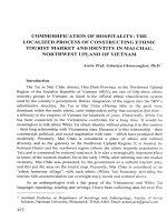
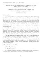
Fig. 1 shows the OOP and IP hysteresis loops for selected
samples with different soft layer thicknesses (tsoft ). The data
clearly reveal that the competition between IMA of the soft
layer and the PMA of the Co/Pd MLs has a dramatic effect
on the magnetization reversal as tsoft is varied. When the soft
layer is very thin (e.g., tNiFe = 3 nm), a significant PMA is still
maintained as the OOP loops shows a large OOP remanence,
relatively small saturation field, and large coercivity, whereas
the IP loop displays characteristic hard axis behavior. This
indicates that the thin soft layer is rigidly coupled to the
Co/Pd MLs during reversal. However, as tsoft increases, the
IMA of the soft layer begins to dominate and the effective
PMA is significantly reduced. As is clearly observable in
Fig. 1(a), (c), and (e), the OOP remanence and saturation
field increase dramatically with tsoft ; this increase is accompanied by a corresponding decrease in the OOP coercivity.
The coercivity is reduced from 770 Oe to 310 Oe for
[Co/Pd]–NiFe system, to 295 Oe for [Co/Pd]–Co system,
and to 440 Oe for [Co/Pd]–CFB system, respectively. The
coercivity field is reduced drastically by a factor of 2 when the
thickness of NiFe reaches 10 nm, Co reaches 5 nm, and CFB
reaches 3.8 nm. This behavior is a typical two-phase system
[25]–[28]. The complementary trends are also observed for the
IP loops; when tsoft is increased the IP loops turn from hard to
easy axis behavior, as shown in Fig. 1(b), (d), and (f). A clear
Fig. 1.
Hysteresis loops with various tsoft for the A, B, and C series,
respectively. (a), (c), and (e) OOP loops with the magnetic field applied
perpendicular to the samples plane. (b), (d), and (f) IP loops with the field
applied in plane. All measurements are normalized with their Msat .
decrease in the IP saturation field with tsoft is observed. When
the tsoft is further increased, the soft layer becomes mostly IP
(e.g., tNiFe = 10 nm).
We carried out micromagnetic simulations to gain further
insight and quantitatively estimate the magnetization tilting
in these three systems. The calculations were based on a
1-D micromagnetic model. The magnetic configuration of each
layer was calculated by minimizing the system’s Gibbs free
energy with respect to the local magnetization angle θ (z).
In the continuous medium approximation the Gibbs free
energy with magnetic field H Z applied perpendicular to the
layer (i.e., along the z-axis) is given as follows:
2
G=
di
(−1)i
i=1
Ai
o
∂θ (z)
∂z
2
1
+ K i − μo Mi2 sin2 θ (z) − μo Mi Hz cos θ (z) dz (1)
2
in which i = 1 refers to Co/Pd MLs and i = 2 refers to
the IMA layers. The layer thickness, di ; exchange stiffness,
Ai ; magnetocrystalline anisotropy, K i ; and saturation magnetization, Mi ; are used as material specific input parameters;
θ (z) refers to the angle between the z-axis and the magnetization vector. Positive K i values correspond to an intrinsic
easy-axis perpendicular to the film plane. We consider the
anisotropy constants as effective values that include volume,
surface, and interface contributions. The interface between
the Co/Pd MLs and the soft layers is located at z = 0.
The equilibrium state is determined by solving the Euler’s
equation with the Weierstrass–Erdmann boundary conditions
[40], [41].
Material parameters used for simulation are shown in
Table I. The materials parameters for the Co/Pd ML, con-
NGUYEN et al.: INVESTIGATION OF THE TUNABILITY OF THE SPIN CONFIGURATION
2004906
TABLE I
M AGNETIC PARAMETERS U SED FOR S IMULATION
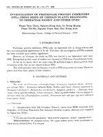
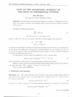
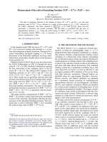
Fig. 2. Normalized OOP remanence (Mr /M S ) from experiment (solid black,
red, and blue symbols) and simulations (solid black, red, and blue lines) as
functions of tNiFe , tCo , and tCFB , respectively.
sidered as a continuous single slab, and for NiFe were
taken from previous studies, [25], [26]: K 1 = 0.63 MJ/m3 ,
M1 = 0.365 MA/m, A1 = 6 pJ/m, K 2 = 0 MJ/m3 , and
A2 = 13 pJ/m. We note that K 2 = 0.45 MJ/m3 for Co since
Co has a uniaxial IMA [42]. One may also consider a uniaxial
IMA for the CFB layers. However, its value is typically low
(K IP ≈ 103 J/m3 ) [43] and can in principle be ignored
compared with the shape anisotropy (0.5 μo M S2 ≈ 106 J/m3 ).
Based on PhaseFMRTM measurements of single NiFe and
CFB films, both M S of NiFe and CFB were found to be
strongly dependent on film thickness (not shown). The thickness dependence of M S is considered particularly in ultrathin
CFB (tCFB ≤ 5.0 nm), reportedly attributed to a magnetically
dead layer [12], [13], [44], [45], [48]. In the thicker CFB
films, the value of M2 = 0.83 MA/m was measured and in
good agreement with prior reports, e.g., in [49]. Addressing
those parameters is critical for the simulations because of the
strong dependence of the IMA on thickness and saturation
magnetization.
The experimental and simulated OOP reduced remanence
values (Mr /M S ) are shown in Fig. 2 as a function of the IMA
soft layer thickness. The graphs reveal a good quantitative
match between theory and experiment for tNiFe > 4.8 nm,
tCo > 2.3 nm, and tCFB > 1.1 nm in the three systems.
For tNiFe < 4.8 nm, tCo < 2.3 nm, and tCFB < 1.1 nm, the
experimental Mr /M S is slightly smaller than the calculated
one. This discrepancy is likely due to finite temperature effects
leading to a slight reduction in the experimentally measured
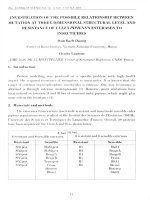
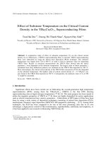
Fig. 3. (a)–(c) Calculated tilt angle, θ (z), through the entire film thickness
and that of the upper most soft layer, θTop (black solid lines), for series
samples A, B, and C, respectively.
remanence [25], [53]. As tsoft is increased, the IMA in the
soft layer begins to compete with the PMA of the Co/Pd ML.
These results are consistent with the fact that thin soft layers
(tNiFe < 4.8 nm, tCo < 2.3 nm, and tCFB < 1.1 nm) are
rigidly coupled with Co/Pd ML, resulting in a dominant OOP
remanent magnetization. However, the tilt angle of the soft
layers begins to deviate from OOP as tsoft further increases,
resulting in a rapid reduction in Mr /M S . The tNiFe = 4.8 nm,
tCo = 2.3 nm, and tCFB = 1.1 nm are so-called critical thicknesses (tC ). The OOP remanence in all three systems shows a
clear decrease when tsoft is larger than tC indicating significant
tilting of the magnetization away from the film normal.
Of particular interest for our work is the angle of the
magnetization through the entire film stacks, denoted θ (z).
Fig. 3(a)–(c) show the simulated θ (z) at remanence through the
entire [Co/Pd]–NiFe, [Co/Pd]–Co, and [Co/Pd]–CFB stacks
for different thicknesses of the IMA soft layers. The magnetization in all three systems is highly tunable and can be
continuously varied by simply changing tsoft . For STOs with
tilted spin polarizing fixed layer, the angle at the top of the
IMA soft layer, θTop, is the most important, and its thickness
2004906
IEEE TRANSACTIONS ON MAGNETICS, VOL. 50, NO. 6, JUNE 2014
These results reveal that using different soft materials results
in a wide range of useful tilt angles, different transition
regions, and different degrees of nonuniformity of the magnetization profile. This can be easily understood by considering the
different material parameters of the CFB and Co, in particular
the larger magnetization M2 , as compared with the NiFe.
This difference results in a smaller effective anisotropy, the
second term of (1). Therefore, the CFB and Co, having a
relatively larger IMA, is far less susceptible to the influence
of the [Co/Pd]5 PMA stack, making possible, a smaller tC ,
and a smaller transition region. Additionally, the difference
in exchange stiffness between the [Co/Pd]5 MLs and CFB is
relatively large, which promotes a larger degree of nonuniformity of the magnetization profile of Co/Pd–CFB system.
As mentioned above, the thickness dependence of M S , and
therefore the effective anisotropy, in IMA materials affects the
range of tilt angle as well.
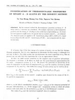
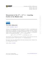
To quantify and illustrate the degree of nonuniformity
in the PMA and IMA layers, respectively, Fig. 4 shows
the magnetization tilt angle variation through the [Co/Pd]5
MLs (solid dots) and through the soft layer (empty dots)
for all three series samples. The solid lines are fits using
the a ∗ [1 − exp(−(t − tC )/t O ]. The model fits all three
data sets well, which allows us to compute the difference
between the angle variations through Co/Pd MLs and through
the IMA soft layer. The nonuniformity is strongly dependent on the IMA material. The fits show that the angle
variation through the [Co/Pd]5 MLs and through the IMA
soft layer in Co/Pd–Co and Co/Pd–CFB present a larger
difference, as compared to Co/Pd–NiFe. In Co/Pd–Co and
Co/Pd–CFB systems, the fitting coefficient, a, for Co/Pd MLs
is about twice that of the IMA soft layer, however, it is nearly
the same in the Co/Pd–NiFe system. The critical thicknesses
resulting from the fits are also in a good agreement with
simulated values in Fig. 3. While the useful tCo and tCFB
ranges are significantly narrower than that observed in the
[Co/Pd]–NiFe material system, they are still well within the
tolerances of standard MRAM and read head processes, where
sub-Ångström thickness control is easily achieved.
IV. C ONCLUSION
Fig. 4. (a)–(c) Angle variation through the [Co/Pd]5 MLs (solid dots) and
through the upper most soft layer (empty dots) for series samples A, B, and C,
respectively. The solid lines are fitted using the a ∗ [1 − exp(−(t − tC )/t O ].
dependence is shown as a black solid line in Fig. 3(a)–(c).
Our calculations reveal that the magnetization in the IMA
soft layers rotates from completely OOP (0°), at the [Co/Pd]5
interface, toward the film plane through the thickness as tsoft
is increased. We find that the tilt angle can be easily tuned
and readily varied from 0° to 70° by simply changing tNiFe
between 5.3 and 10 nm, while it varies from 0° to 68° for
2.3 nm < tCo < 5 nm and from 0° to 72° for 1.1 nm < tCFB <
5 nm. This is a significant improvement over the tunable range
than previously reported [25]. The 5.3 nm < tNiFe < 10 nm,
2.3 nm < tCo < 5 nm, and 1.1 nm < tCFB < 5 nm are
so-called transition regions in which the magnetization angle
can be tunable.
In summary, we have carried out a systematic study of the
spin configuration in OOP/IP exchange springs with various
IP soft layer materials. Taking advantage of the competition
between the PMA and IMA in these systems we find that
the entire magnetization profile can be tuned with respect to
both magnetization angle and degree of nonuniformity. Both
experiments and simulations conclude that the spins in the
soft layer remain essentially perpendicular to the film plane
for tsoft ≤ tC . However, a well defined tilt angle is achievable
for tsoft > tC . The range of angles and uniformity can be easily
tuned by changing the soft material and its thickness. These
tailored exchange springs are thus particularly useful not only
as the fixed but also as the free layers in spin-torque driven
devices, which can broaden the scope of potential applications.
Specifically, the exchange spring magnets based on CFB soft
layers can be applied in MgO-based MTJ systems. This paper,
therefore, provides meaningful insights for future utilization in
STT-MRAM or STO devices.
NGUYEN et al.: INVESTIGATION OF THE TUNABILITY OF THE SPIN CONFIGURATION
ACKNOWLEDGMENT
This work was supported in part by the EC FP7 under
Contract ICT-257159 “MACALO,” in part by the Swedish
Foundation for Strategic Research, in part by the Swedish
Research Council, and in part by the Knut and Alice Wallenberg Foundation. The work of T. N. A. Nguyen was supported
in part by the National Foundation for Science and Technology
Development of Vietnam under Project 03.02-2010.27 and in
part by the KIST-IRDA under Alumni Project 2Z03750. The
work of C. W. Miller was supported by NSF-ECCS. The work
of J. Åkerman was supported by a grant through the Knut and
Alice Wallenberg Foundation.
R EFERENCES
[1] J. C. Slonczewski, “Current-driven excitation of magnetic multilayers,”
J. Magn. Magn. Mater., vol. 159, nos. 1–2, pp. L1–L7, Jun. 1996.
[2] L. Berger, “Emission of spin waves by a magnetic multilayer traversed
by a current,” Phys. Rev. B, vol. 54, no. 13, pp. 9353–9358, 1996.
[3] D. C. Ralph and M. D. Stiles, “Spin transfer torques,” J. Magn. Magn.
Mater., vol. 320, no. 7, pp. 1190–1216, 2008.
[4] S. Kaka, M. R. Pufall, W. H. Rippard, T. J. Silva, S. E. Russek, and
J. A. Katine, “Mutual phase-locking of microwave spin torque nanooscillators,” Nature, vol. 437, pp. 389–392, Sep. 2005.
[5] J. Slonczewski, “Excitation of spin waves by an electric current,”
J. Magn. Magn. Mater., vol. 195, no. 2, pp. 261–268, 1999.
[6] S. Mangin, D. Ravelosona, J. A. Katine, M. J. Carey, B. D. Terris, and
E. E. Fullerton, “Current-induced magnetization reversal in nanopillars
with perpendicular anisotropy,” Nature Mater., vol. 5, no. 3, pp. 210–215,
2006.
[7] J. Åkerman, “Applied physics. Toward a universal memory,” Science,
vol. 308, no. 5721, pp. 508–510, Apr. 2005.
[8] J. P. Wang, Y. Y. Zou, C. H. Hee, T. C. Chong, and Y. F. Zheng,
“Approaches to tilted magnetic recording for extremely high areal
density,” IEEE Trans. Magn., vol. 39, no. 4, pp. 1930–1935, Jul. 2003.
[9] M. Albrecht, G. Hu, I. L. Guhr, T. C. Ulbrich, J. Boneberg, P. Leiderer,
et al., “Magnetic multilayers on nanospheres,” Nature Mater., vol. 4,
no. 3, pp. 203–206, 2005.
[10] J.-P. Wang, “Magnetic data storage: Tilting for the top,” Nat. Mater.,
vol. 4, pp. 191–192, Mar. 2005.
[11] Y. Zhou, C. L. Zha, S. Bonetti, J. Persson, and J. Akerman, “Spintorque oscillator with tilted fixed layer magnetization,” Appl. Phys. Lett.,
vol. 92, no. 26, pp. 262508-1–262508-3, 2008.
[12] R. Sbiaa, R. Law, E.-L. Tan, and T. Liew, “Spin transfer switching
enhancement in perpendicular anisotropy magnetic tunnel junctions with
a canted in-plane spin polarizer,” J. Appl. Phys., vol. 105, no. 1,
pp. 013910-1–013910-6, 2009.
[13] P.-B. He, R.-X. Wang, Z.-D. Li, Q.-H. Liu, A.-L. Pan, Y.-G. Wang,
et al., “Current-driven magnetization dynamics in magnetic trilayers with
a tilted spin polarizer,” Eur. Phys. J. B, vol. 73, no. 3, pp. 417–421,
Jan. 2010.
[14] Y. Zhou, C. L. Zha, S. Bonetti, J. Persson, and J. Akerman, “Microwave
generation of tilted-polarizer spin torque oscillator,” J. Appl. Phys.,
vol. 105, no. 7, pp. 07D116-1–07D116-3, 2009.
[15] Y. Zhou, S. Bonetti, C. L. Zha, and J. Åkerman, “Zero-field precession
and hysteretic threshold currents in a spin torque nano device with tilted
polarizer,” New J. Phys., vol. 11, no. 10, p. 103028, 2009.
[16] M. Hoefer, T. Silva, and M. Keller, “Theory for a dissipative droplet
soliton excited by a spin torque nanocontact,” Phys. Rev. B, vol. 82,
no. 5, pp. 054432-1–054432-14, 2010.
[17] M. Hoefer, M. Sommacal, and T. Silva, “Propagation and control of
nanoscale magnetic-droplet solitons,” Phys. Rev. B, vol. 85, no. 21,
pp. 214433-1–214433-7, 2012.
[18] S. M. Mohseni, S. Chung, S. R. Sani, E. Iacocca, R. K. Dumas,
T. N. A. Nguyen, et al., “Spin torque–generated magnetic droplet
solitons,” Science, vol. 339, no. 6125, pp. 1295–1298, 2013.
[19] S. M. Mohseni, S. R. Sani, J. Persson, T. N. A. Nguyen, S. Chung,
Y. Pogoryelov, et al., “Magnetic droplet solitons in orthogonal nanocontact spin torque oscillators,” Phys. B, Condensed Matter, 2013, to be
published.
2004906
[20] S. M. Mohseni et al., “Spin transfer torque generated magnetic droplet
solitons,” J. Appl. Phys., 2013, to be published.
[21] Y. F. Zheng, J. P. Wang, and V. Ng, “Control of the tilted orientation
of CoCrPt/Ti thin film media by collimated sputtering,” J. Appl. Phys.,
vol. 91, no. 10, pp. 8007–8009, 2002.
[22] C. L. Zha, R. K. Dumas, J. Persson, S. M. Mohseni, J. Nogu, and J.
Akerman, “Pseudo spin valves using a (112)-textured D022 Mn2.3 –2.4 Ga
fixed layer,” IEEE Magn. Lett., vol. 1, p. 2500104, Dec. 2010.
[23] C. L. Zha, J. Persson, S. Bonetti, Y. Y. Fang, and J. Akerman, “Pseudo
spin valves based on L10 (111)-oriented FePt fixed layers with tilted
anisotropy,” Appl. Phys. Lett., vol. 94, no. 16, pp. 163108-1–163108-3,
2009.
[24] C. L. Zha, Y. Y. Fang, J. Nogués, and J. Akerman, “Improved magnetoresistance through spacer thickness optimization in tilted pseudo spin
valves based on L10 (111)-oriented FePtCu fixed layers,” J. Appl. Phys.,
vol. 106, no. 5, pp. 053909-1–053909-4, Sep. 2009.
[25] T. N. A. Nguyen, Y. Fang, V. Fallahi, N. Benatmane, S. M. Mohseni,
R. K. Dumas, et al., “[Co/Pd]–NiFe exchange springs with tunable magnetization tilt angle,” Appl. Phys. Lett., vol. 98, no. 17,
pp. 172502-1–172502-3, 2011.
[26] S. Chung, S. M. Mohseni, V. Fallahi, T. N. A. Nguyen, N. Benatmane,
R. K. Dumas, et al., “Tunable spin configuration in [Co/Ni]-NiFe
spring magnets,” J. Phys. D, Appl. Phys., vol. 46, no. 12, p. 125004,
2013.
[27] T. N. A. Nguyen, N. Benatmane, V. Fallahi, Y. Fang, S. M. Mohseni, R.
K. Dumas, et al., “[Co/Pd]4–Co–Pd–NiFe spring magnets with highly
tunable and uniform magnetization tilt angles,” J. Magn. Magn. Mater.,
vol. 324, no. 22, pp. 3929–3932, 2012.
[28] S. Tacchi, T. N. A. Nguyen, G. Carlotti, G. Gubbiotti, M. Madami,
R. K. Dumas, et al., “Spin wave excitations in exchange-coupled
[Co/Pd]-NiFe films with tunable tilting of the magnetization,” Phys. Rev.
B, vol. 87, no. 14, pp. 144426-1–144426-5, 2013.
[29] V. V. Kruglyak, S. O. Demokritov, and D. Grundler, “Magnonics,”
J. Phys. D, Appl. Phys., vol. 43, no. 26, p. 260301, 2010.
[30] M. Madami, S. Bonetti, G. Consolo, S. Tacchi, G. Carlotti, G. Gubbiotti,
et al., “Direct observation of a propagating spin wave induced by spintransfer torque,” Nature Nanotechnol., vol. 6, no. 10, pp. 635–638,
2011.
[31] J. Bonetti and S. Åkerman, “Nano-contact spin-torque oscillators as
magnonic building blocks,” Topics Appl. Phys., vol. 125, pp. 177–187,
2013.
[32] L. Gan, R. D. Gomez, C. J. Powell, R. D. McMichael, P. J. Chen, and
W. F. Egelhoff, “Thin Al, Au, Cu, Ni, Fe, and Ta films as oxidation
barriers for Co in air,” J. Appl. Phys., vol. 93, no. 10, p. 8731,
2003.
[33] B. Cui, C. Song, Y. Y. Wang, W. S. Yan, F. Zeng, and F. Pan, “Tuning
of uniaxial magnetic anisotropy in amorphous CoFeB films,” J. Phys.
Condensed Matter., vol. 25, no. 10, p. 106003, 2013.
[34] Y. Masugata, S. Ishibashi, H. Tomita, T. Seki, T. Nozaki, Y. Suzuki,
et al., “Spin-torque induced rf oscillation in magnetic tunnel junctions
with an Fe-rich CoFeB free layer,” J. Phys., Conf. Ser., vol. 266, no. 1,
p. 012098, 2011.
[35] Z. Zeng, G. Finocchio, B. Zhang, P. K. Amiri, J. A. Katine,
I. N. Krivorotov, et al., “Ultralow-current-density and bias-fieldfree spin-transfer nano-oscillator,” Sci. Rep., vol. 3, p. 1426,
Mar. 2013.
[36] Z. Zhang, X. Fan, M. Lin, D. Guo, G. Chai, and D. Xue, “Optimized
soft magnetic properties and high frequency characteristics of obliquely
deposited Co–Zr thin films,” J. Phys. D, Appl. Phys., vol. 43, no. 8,
p. 085002, 2010.
[37] D. O. Smith, M. S. Cohen, and G. P. Weiss, “Oblique-incidence
anisotropy in evaporated permalloy films,” J. Appl. Phys., vol. 31, no. 10,
pp. 1755–1762, 1960.
[38] I. Barsukov, P. Landeros, R. Meckenstock, J. Lindner, D. Spoddig,
Z.-A. Li, et al., “Tuning magnetic relaxation by oblique deposition,”
Phys. Rev. B, vol. 85, no. 1, pp. 014420-1–014420-6, 2012.
[39] N. N. Phuoc and C. K. Ong, “Non-linear interplay between exchangebias-induced unidirectional anisotropy and oblique-deposition-induced
uniaxial anisotropy,” J. Appl. Phys., vol. 114, no. 4, p. 043911,
2013.
[40] G. Asti, M. Ghidini, R. Pellicelli, C. Pernechele, and M. Solzi,
“Magnetic phase diagram and demagnetization processes in perpendicular exchange-spring multilayers,” Phys. Rev. B, vol. 73, no. 9,
pp. 094406-1–094406-16, 2006.
2004906
[41] T. Leineweber and H. Kronrniiller, “Micromagnetic examination of
exchange coupled ferromagnetic nanolayers,” J. Magn. Magn. Mater.,
vol. 176, nos. 2–3, pp. 145–154, 1997.
[42] J. Brandenburg, R. Hühne, L. Schultz, and V. Neu, “Domain structure of
epitaxial Co films with perpendicular anisotropy,” Phys. Rev. B, vol. 79,
no. 5, pp. 054429-1–054429-7, 2009.
[43] M. Raju, S. Chaudhary, and D. K. Pandya, “Effect of interface on magnetic properties of Co20 Fe60 B20 in ion-beam sputtered Si/CoFeB/MgO
and Si/MgO/CoFeB bilayers,” J. Magn. Magn. Mater., vol. 332, pp.
109–113, Apr. 2013.
[44] K. Oguz, P. Jivrajka, M. Venkatesan, G. Feng, and J. M. D. Coey,
“Magnetic dead layers in sputtered Co40 Fe40 B20 films,” J. Appl. Phys.,
vol. 103, no. 7, pp. 07B526-1–07B526-3, 2008.
[45] P. K. Amiri, Z. M. Zeng, J. Langer, H. Zhao, G. Rowlands, Y.-J. Chen,
et al., “Switching current reduction using perpendicular anisotropy in
CoFeB-MgO magnetic tunnel junctions,” Appl. Phys. Lett., vol. 98,
no. 11, p. 112507, 2011.
[46] S. Ingvarsson, G. Xiao, S. S. P. Parkin, and W. J. Gallagher,
“Thickness-dependent magnetic properties of Ni81 Fe19 , Co90 Fe10 and
Ni65 Fe15 Co20 thin films,” J. Magn. Magn. Mater., vol. 251, no. 2,
pp. 202–206, 2002.
[47] Y. Xu, D. Zhang, Y. Zhai, J. Chen, J. G. Long, H. Sang, et al., “FMR
study on magnetic thin and ultrathin Ni-Fe films,” Phys. Status Solidi
(C), vol. 1, no. 12, pp. 3698–3701, 2004.
IEEE TRANSACTIONS ON MAGNETICS, VOL. 50, NO. 6, JUNE 2014
[48] S. Y. Jang, C.-Y. You, S. H. Lim, and S. R. Lee, “Annealing effects on
the magnetic dead layer and saturation magnetization in unit structures
relevant to a synthetic ferrimagnetic free structure,” J. Appl. Phys.,
vol. 109, no. 1, pp. 013901-1–013901-5, 2011.
[49] K. Lee, J. J. Sapan, S. H. Kang, and E. E. Fullerton, “Perpendicular magnetization of CoFeB on single-crystal MgO,” J. Appl. Phys., vol. 109,
no. 12, p. 123910, 2011.
[50] C. J. Kinane, A. K. Suszka, C. H. Marrows, B. J. Hickey, D. A. Arena,
J. Dvorak, et al., “Soft x-ray resonant magnetic scattering from an
imprinted magnetic domain pattern,” Appl. Phys. Lett., vol. 89, no. 9,
pp. 092507-1–092507-3, 2006.
[51] R. S. Iskhakov, N. A. Shepeta, S. V. Stolyar, L. A. Chekanova, and
V. Y. Yakovchuk, “Spin-wave resonance in Co/Pd magnetic multilayers
and NiFe/Cu/NiFe three-layered films,” JETP Lett., vol. 83, no. 1,
pp. 28–32, Mar. 2006.
[52] H. Sato et al., “CoFeB thickness dependence of thermal stability factor
in CoFeB/MgO perpendicular magnetic tunnel junctions,” IEEE Magn.
Lett., vol. 3, p. 3000204, Apr. 2012.
[53] R. Skomski, P. Kumar, G. C. Hadjipanayis, and D. J. Sellmyer, “FiniteTemperature Micromagnetism,” IEEE Trans. Magn., vol. 49, no. 7,
pp. 3229–3232, Jul. 2013.