Cross linkable polymers containing a triple bond backbone and their application in photovoltaic devices
Bạn đang xem bản rút gọn của tài liệu. Xem và tải ngay bản đầy đủ của tài liệu tại đây (1.78 MB, 25 trang )
View Article Online
View Journal
RSC Advances
This article can be cited before page numbers have been issued, to do this please use: T. T. T. Bui, S.
Park, M. Jahandar, C. E. Song, S. K. Lee, J. Lee, S. Moon and W. S. Shin, RSC Adv., 2016, DOI:
10.1039/C6RA08162B.
This is an Accepted Manuscript, which has been through the
Royal Society of Chemistry peer review process and has been
accepted for publication.
Accepted Manuscripts are published online shortly after
acceptance, before technical editing, formatting and proof reading.
Using this free service, authors can make their results available
to the community, in citable form, before we publish the edited
article. This Accepted Manuscript will be replaced by the edited,
formatted and paginated article as soon as this is available.
You can find more information about Accepted Manuscripts in the
Information for Authors.
Please note that technical editing may introduce minor changes
to the text and/or graphics, which may alter content. The journal’s
standard Terms & Conditions and the Ethical guidelines still
apply. In no event shall the Royal Society of Chemistry be held
responsible for any errors or omissions in this Accepted Manuscript
or any consequences arising from the use of any information it
contains.
www.rsc.org/advances
Page 1 of 24
RSC Advances
View Article Online
DOI: 10.1039/C6RA08162B
RSC Advances
Full paper
Photovoltaic Devices
Thi Thu Trang Bui,1,2 Sangheon Park,1,4 Muhammad Jahandar,1,3 Chang Eun Song,1 Sang Kyu Lee,1,3
Jong-Cheol Lee,1,3 Sang-Jin Moon, 1, 3 Won Suk Shin *,1,3
1
Energy Materials Research Center, Korea Research Institute of Chemical Technology (KRICT),
141 Gajeongro, Yuseong, Daejeon, 305-600, Korea
2
3
Faculty of Environment, Vietnam National University of Agriculture, Hanoi, Vietnam
Department of Nanomaterials Science and Engineering, University of Science and Technology
(UST), 217 Gajeongro, Yuseong, Daejeon, 305-350, Korea
4
Department of Physics, Sungkyunkwan University (SKKU), 2066 Seoburo, Jangan, Suwon,
Gyeong Gi-do, Korea
RSC Advances Accepted Manuscript
Published on 10 June 2016. Downloaded by Weizmann Institute of Science on 12/06/2016 09:19:09.
Cross-linkable Polymers Containing Triple Bond Backbone and Their Application in
RSC Advances
Page 2 of 24
View Article Online
DOI: 10.1039/C6RA08162B
Abstract
Two novel polymers containing triple bond in backbone with different conjugated types
(acceptor-acceptor, acceptor-donor structures) were synthesized and investigated the crosslinking
spectroscopy, and found that crosslinked polymers have given the solvent resistance properties
during the following solvent washing with the similar solvent for active layer. Two triple bond
polymers were used as buffer layer materials to modify the interface properties of electronselective ZnO in the inverted PSCs via spin-coating process. Effects of buffer layer on the
surface of ZnO were studied via atomic force microscopy and contact angle measurement. The
increased hydrophobic nature of ZnO surface resulted in better contact with active layer, and led
to improve the performance of photovoltaic devices with the increased FF.
Keywords: Crosslinkable polymers, triple bond-containing polymers, organic solar cells,
inverted solar cells, interlayer.
RSC Advances Accepted Manuscript
Published on 10 June 2016. Downloaded by Weizmann Institute of Science on 12/06/2016 09:19:09.
characteristics under UV irradiation. The crosslink formation was proved via UV-vis and IR
Page 3 of 24
RSC Advances
View Article Online
DOI: 10.1039/C6RA08162B
1. Introduction
Because of many advantages such as lightweight, low cost, flexible substrates, etc. bulk
heterojunction (BHJ) organic solar cells (OSCs) have attracted considerable attention recently.
and reached over 11% by the use of novel polymer and control of the active layer morphology.1, 2
In general, the fabrication of multilayer organic electronic devices including OSCs is carried out
by one of two methods: high-vacuum vapor deposition or solution processing. The high vacuum
vapor deposition can be used for most small molecule-based devices but relatively expensive,
time consuming, difficult to make large-area devices and apply for high-molecular weight
materials.3 In contrast, solution process have potential in facilitate rapid and low-cost processing,
in fabricate in large-size scale, and can be used for all soluble materials. However, during the
multilayer integration, the deposition of second layer from solution can lead to partial dissolve
the previous layer if the solvent for second layer materials also dissolves the first layer
materials.4 This is the big challenge for the solution processing method to fabricate multilayer
devices by compared to high-vacuum vapor deposition method. To overcome this, a number of
efforts have been explored. One of the approaches is developing novel materials that can provide
excellent solvent resistance after thermo- or photo-crosslinking or chemical treatments.5, 6 These
cross-linkable materials can be used as electrode buffer layer materials7, 8 to modify interfacial
properties of charge transporting layer of organic electronic devices.
In the past, triple bond containing polymers in the pendant or backbone were found to easily
undergo crosslinking on exposure to ultraviolet light and the crosslink reaction could also be
sensitized by additives.9,
10
The formation of only a few fractions of crosslinks is probably
sufficient to insolubilize the polymer. So, triple bond containing polymer is one of the potential
candidates as the crosslinkable material which can be used for fabricating multilayer devices by
solution processing. In this regard, we firstly tried the synthesis of a series of polymers
containing triple bond with different conjugated backbone structure, donor-acceptor (D-A),
donor-donor (D-D), and acceptor-acceptor (A-A). Two polymers, D-A and A-A, were tested the
crosslinkability under UV irradiation. We expected the crosslinked layer was not washed out
when the next layer was introduced. Then these polymers were used as buffer layers on top of
ZnO to improve the performance of inverted polymer solar cells (PSCs).
RSC Advances Accepted Manuscript
Published on 10 June 2016. Downloaded by Weizmann Institute of Science on 12/06/2016 09:19:09.
During the past decade, the power conversion efficiency (PCE) has been increased significantly
RSC Advances
Page 4 of 24
View Article Online
DOI: 10.1039/C6RA08162B
2. Experimental section
2.1. Instruments and characterization
Molecular weights were determined with GPC on Viscotek TSA302 Triplet Detector Array
recorded on a Shimadzu UV-3600 UV-visible spectrometer. The samples for UV-vis absorption
measurements were prepared by spin-coated the solution of polymer in chloroform on cleaned
quartz glass substrates. CV was measured by using IviumStat instrument. CV is conducted with a
scan rate of 50 mV s-1 at room temperature under the protection of argon with 0.1M
tetrabutylammonium tetrafluoroborate in acetonitrile as the electrolyte. A platinum electrode was
coated with a thin copolymer film and used as the working electrode. A Pt wire was used as the
counter electrode, and a Ag/AgNO3 (0.1 M) electrode was used as the reference electrode.
2.2. Fabrication and characterization of polymer solar cells
The structure of BHJ device is ITO/ZnO/Interlayer polymer/P3HT:PC61BM (1.0:0.8
w/w)/MoOx/Al. To fabricate PSCs, first, ITO coated glass slides were cleaned by detergent,
followed by ultrasonic washing in D.I. water, acetone and IPA subsequently, and dried in an
oven overnight. After UV-ozone treatment for 10 min, ZnO solution was spin-coated onto the
ITO substrate at 6000 rpm for 40 s and then annealed at 200 oC for 1 hour. For deposition of the
active layer, P3HT:PC61BM (1.0:0.8 w/w) dissolved in o-DCB were spin-cast on top of the ZnO
layer in a nitrogen-filled glove box. Finally, metal top electrode, MoOx and Ag, were
sequentially deposited onto BHJ active layer in vacuum (< 2 × 10⁻⁶ Torr) by thermal evaporation.
The J-V characteristics of the devices were recorded by solar simulator using Keithley 2400
source measure unit. The characterization of un-encapsulated solar cells was carried out in air
under illumination of AM 1.5G, 100 mW cm–2, using a solar simulator (McScience, Inc.) with
xenon light source. Illumination intensity was set using an NREL certified silicon diode with an
integrated KG5. The external quantum efficiency (EQE) was measured using a reflective
microscope objective to focus the light output from a 100 W halogen lamp outfitted with a
monochrometer and an optical chopper (McScience, Inc.).
RSC Advances Accepted Manuscript
Published on 10 June 2016. Downloaded by Weizmann Institute of Science on 12/06/2016 09:19:09.
system in CHCl3 using polystyrene standard at room temperature. Absorption spectra were
Page 5 of 24
RSC Advances
View Article Online
DOI: 10.1039/C6RA08162B
2.3. Materials
2,7-Diromo-9,9-didecylfluorene;11 4,7-bisethynyl-2,1,3-benzothiadiazole;12 2,5-bis(5-bromo-3hexylthiophene-2-yl)thiazolo[5,4-d]thiazole;13 N- heptadecan-9’-yl-2,7-dibromocarbazole14 were
were purchased from Sigma Aldrich, Tokyo Chemical Industry Co., LTD and 4Chem Laboratory.
All chemicals were used as received. Other monomers were synthesized according to Scheme 1.
Preparation of 2,7-bis(2-trimethylsilyl)ethynyl-9,9-didecylfluorene
A mixture of 2,7-diromo-9,9-didecylfluorene (12.090 g, 20 mmol), tetrakis (triphenylphosphine
palladium (0)) (0.464 g, 0.4 mmol), copper (I) iodide (0.152 g, 0.8 mmol) and trimethylsilyl
acetylene (5.893g, 60.00 mmol) was dissolved in 140 mL triethylamine. The reaction mixture
was stirred at 75 oC for overnight under Ar atmosphere. After cooled to room temperature, the
solvent of reaction was removed under reduced pressure. The residue was extracted with CH2Cl2.
The organic layer was washed with cool water and aqueous 1.2 N HCl then dried over anhydrous
MgSO4, and finally evaporated under reduced pressure. The crude was purified by silica gel
column
chromatography
eluting
with
CH2Cl2/hexane
(1:4)
to
obtain
2,7-bis(2-
trimethylsilyl)ethynyl-9,9-didecylfluorene (12.66 g, 99%) as the yellow oil.
1
H-NMR (300 MHz, CDCl3, δ ppm): 7.60 (d, 2H), 7.46 (dd, 2H), 7.42 (s, 2), 1.77-1.71 (m, 4H),
1.12-0.83 (m, 32H), 0.72-0.64 (t, 6H), 0.40 (s, 18H)
Preparation of 2,7-bisethynyl-9,9-didecylflourene
A mixture of 2,7-bis(2-trimethylsilyl)ethynyl-9,9-didecylfluorene (12.660 g, 19.80 mmol) in 500
mL of 1 mol L-1 KOH methanol solution was stirred at room temperature in the dark for 1 hour.
The reaction mixture was poured into cool water (1000 mL) and extracted with CH2Cl2 several
times. The combined organic layers were dried over anhydrous MgSO4 and then removed
solvent. The residue was further purified by using silica gel column chromatography (hexane as
RSC Advances Accepted Manuscript
Published on 10 June 2016. Downloaded by Weizmann Institute of Science on 12/06/2016 09:19:09.
synthesized according to the procedures reported in the literature. Another reagents and solvents
RSC Advances
Page 6 of 24
View Article Online
DOI: 10.1039/C6RA08162B
an eluent) to afford 2,7-bis ethynyl-9,9-didecylfluorene as yellow oil (8.56 g, 87%). This
compound was stored in the dark under nitrogen at 10°C.
1
H-NMR (300 MHz, CDCl3, δ ppm): 7.60 (d, 2H), 7.45 (d, 2H), 7.41 (s, 2), 3.06 (s, 2H), 1.77-
General procedure to synthesize polymers containing triple bond
In a sealed tube, diromo-compound (1 eq.), bisethynyl-compound (1 eq.) , Pd(PPh3)4 (0.1 eq.)
and CuI (0.2 eq.) were dissolved in mixed solvent of THF and triethylamine (TEA) (2/1, v/v)
under nitrogen atmosphere. The mixture was further frozen, evacuated, and thawed three times to
further remove oxygen in the solvent. Then the mixture was stirred at 90 °C in the dark for 48 h.
After the resulting solution was cooled down to room temperature, it was then poured into
methanol (300 mL). The resulting precipitate was collected by filtration, and the product was
further purified by Soxhlet extraction with methanol, acetone and CHCl3 successively. The
CHCl3 extraction was removed solvent and then precipitated by methanol. Finally, it was
collected by filtration and dried in vacuum oven.
Preparation of poly[9,9-bisdecylfluorene-2,7-diyl-ethynylene-alt-4,7-(2,1,3,-benzothiadiazole)]
(D-A polymmer)
2,7-Diromo-9,9-didecylfluorene (241.1 mg, 0.40 mmol), 4,7-bisethynyl-2,1,3-benzothiadiazole
(73.7 mg, 0.40 mmol), Pd(PPh3)4 (46 mg, 0.04 mmol) and CuI (15 mg, 0.08 mmol) were
dissolved in mixed solvent of THF (3.4 mL) and TEA (1.7 mL) under nitrogen atmosphere. The
D-A polymer was obtained as brown solid (125 mg, yield 50%). Mw = 12.2 kg/mol , PDI: 1.487.
Preparation of poly(N-heptadecan-9’-yl-carbazole-2,7-diyl-ethynylene-9,9-bisdecylfluorene) (DD polymer)
RSC Advances Accepted Manuscript
Published on 10 June 2016. Downloaded by Weizmann Institute of Science on 12/06/2016 09:19:09.
1.71 (m, 4H), 1.12-0.89 (m, 32H), 0.72-0.64 (t, 6H)
Page 7 of 24
RSC Advances
View Article Online
DOI: 10.1039/C6RA08162B
2,7-Bisethynyl-9,9-didecylflourene
(203.4
mg,
0.40
mmol),
N-
heptadecan-9’-yl-2,7-
dibromocarbazole (225.4 mg, 0.40 mmol), Pd(PPh3)4 (46 mg, 0.04 mmol) and CuI (15 mg, 0.08
mmol) were dissolve in mixed solvent (THF (5 mL) and Et3N (1.7 mL)) under nitrogen
chlorinated solvent (CHCl3, CB, o-DCB…) even at hot condition.
Preparation of poly[2,5-bis(5-yl-3-hexylthiophene-2-yl)thiazolo[5,4-d]thiazole-ethynylene-alt4,7-(2,1,3,-benzothiadiazole)] (A-A polymer)
2,5-Bis(5-bromo-3-hexylthiophene-2-yl)thiazolo[5,4-d]thiazole (253.0 mg, 0.40 mmol), 4,7bisethynyl-2,1,3-benzothiadiazole (73.7 mg, 0.40 mmol), Pd(PPh3)4 (46 mg, 0.04 mmol) and CuI
(15 mg, 0.08 mmol) were dissolved in mixed solvent of THF (3.4 mL) and Et3N (1.7 mL) under
nitrogen atmosphere. The A-A polymer was obtained as purple solid (70 mg, yield 27%). Mw =
14.0 kg/mol, PDI: 2.576.
RSC Advances Accepted Manuscript
Published on 10 June 2016. Downloaded by Weizmann Institute of Science on 12/06/2016 09:19:09.
atmosphere. The D-D crude polymer was obtained as yellow solid, but insoluble in common
RSC Advances
Page 8 of 24
View Article Online
DOI: 10.1039/C6RA08162B
3. Results and discussion
3.1. Material synthesis
The synthetic routes of monomers and corresponding polymers are illustrated in Scheme 1. The
and
bisethynyl-compounds in the presence of Pd(PPh3)4 and CuI as catalysts and solvent system of
triethylamine (TEA)/ THF (1:2, v/v) via thermal heating for 48 hours to obtain D-A, D-D and AA polymers. However, after reaction, D-D crude product was insoluble in chloroform so we
could not purify and investigate further. Two crude polymer products of D-A and A-A were
precipitated in MeOH and purified by Soxhlet extraction. The pure polymers D-A and A-A
collected from chloroform fraction display high solubility in chlorinated organic solvents such as
chlorobenzene (CB), o-dichlorobenzene (o-DCB), chloroform. The yields of polymerizations to
synthesize D-A and A-A polymers are 50% and 27%, respectively. The number-average
molecular weight (Mn) of D-A and A-A are 12.2 and 14.0 kg mol-1, with polydispersity indexes
(PDIs) of 1.487 and 2.576, respectively, as determined by gel permeation chromatography (GPC)
using chloroform as an eluent calibrated with polystyrene standards.
From the UV spectra of pristine films (Figure 1), the optical properties of two polymers are
summarized in Table 1, and the band gaps of D-A and A-A polymers were calculated to be 2.25
and 1.90 eV, respectively.
3.2. Crosslinkability of the polymers
Crosslinkability of D-A and A-A polymers were investigated via UV-vis spectroscopy and
Infrared (IR) spectroscopy. Crosslink was performed by using UV-irradiation with wavelength of
254 nm. First, the neat polymer films, prepared by spin-coating on quartz substrates, were
exposed on UV light with wavelength of 254 for 10 min under inert gas. After that, these treated
films were measured by UV-vis spectroscopy before and after rinsed by chloroform. Another
polymer film without UV treatment was also rinsed with chloroform and measured UV-vis
spectra for comparison. Figure 1 shows the UV-vis spectra of polymer thin films under different
conditions: pristine, rinsed with chloroform, exposed on UV, rinsed with chloroform after
exposed on UV. In both case of polymers, the absorption spectrum which observed in pristine
films are almost disappeared after rinsed by chloroform. That means, neat thin films can be
mostly washed out by the solvent used for the following spin coating. However, the films
RSC Advances Accepted Manuscript
Published on 10 June 2016. Downloaded by Weizmann Institute of Science on 12/06/2016 09:19:09.
polymers were obtained by Sonogashira cross-coupling reaction between dibromo-
Page 9 of 24
RSC Advances
View Article Online
DOI: 10.1039/C6RA08162B
exposed by UV light maintained most of UV-vis absorption after rinsed with chloroform. So the
generation of cross-linked network seems to be made by exposing UV light. These cross-linked
layers will allow subsequent active layer introduction by spin-coating without destroying them.
fabricated on the surface of KBr plates and measured IR spectra before and after UV exposure to
see the change of vibrational stretching of alkyne functional groups in the polymer backbone. As
can be seen in Figure 2, the vibrational stretching of C≡C group in triple bond at 2191 cm-1 (AA) and 2192 cm-1 (D-A) were significantly reduced after the UV irradiation, proving the
occurrence of cross-linking. The changes of UV spectra shape after UV exposure also support
the structural change of polymers.
3.3. Electrochemical properties
To determine the energy levels of synthesized polymers, cyclic voltammetry (CV) is used. The
result is shown in Figure 3 and Table 1. For calibration, the redox potential of
ferrocene/ferrocenium (Fc/Fc+) is measured and it is located at 0.22 V to the Ag/AgNO3 (0.1 M)
electrode. It is assumed that the redox potential of Fc/Fc+ has an absolute energy level of -4.8 eV
to vacuum.15 Then the energy levels of the highest occupied molecular orbital (HOMO) is then
calculated according to the following equation: EHOMO = -(4.58 + Eox onset) (eV) and the lowest
unoccupied molecular orbital (LUMO) is calculated from EHOMO and optical band gap according
to the following equation: ELUMO = (EHOMO + Egopt) (eV). The first oxidation potential of the D-A
was appeared at Eox = + 1.38 V (versus Ag/Ag+) while in the case of A-A, it was appeared at Eox
= + 0.75 V (versus Ag/AgNO3 (0.1 M), corresponded the HOMO energy levels of D-A and A-A
are -5.96 and -5.33 eV, respectively. Meanwhile, the LUMO energy levels of D-A and A-A were
calculated to be -3.71 and -3.43 eV, respectively.
3.4. The effect of buffer layer on the properties of ZnO surface.
To characterize the ZnO surface before and after using buffer layer with UV treatment, AFM
images were measured and shown in Figure 4. The roughness of ZnO surface are not much
affected by the coating of A-A polymer buffer layer, the root mean square (RMS) roughness of
neat ZnO, ZnO with A-A buffer layer, and ZnO with A-A buffer layer with UV exposure are
0.927, 1.080, and 0.996 nm, respectively. However, in the case of D-A-based buffer layer, the
roughness are significantly increased with the values of 1.551, 1.990 nm, respectively, for the
RSC Advances Accepted Manuscript
Published on 10 June 2016. Downloaded by Weizmann Institute of Science on 12/06/2016 09:19:09.
To prove the cross-linking, IR spectroscopy is performed. The thin films of polymers were
RSC Advances
Page 10 of 24
View Article Online
DOI: 10.1039/C6RA08162B
without and with UV irradiation after D-A polymer introduction on top of ZnO surfaces. The
surface of A-A polymer introduced buffer layer showed the fabric network after UV exposure
which may be formed from the A-A crosslinked polymers, while in the case of D-A polymer, big
The hydrophilicity of the ZnO surface was compared before and after spin-coating buffer layer
via the contact angle measurement using water drop, as shown in Figure 5. The contact angle
was changed from 55.27o to 86.81o (with A-A polymer) and to 75.24o (with D-A polymer) when
buffer layer was applied on the top of ZnO. After UV exposure, A-A crossliked polymer has
contact angle value of 82.65o, which is not much different to the before UV irradiation case,
while for the case of D-A crosslinked polymer, the contact angle clearly decreased to 66.69o. The
maintaining the hydrophobic and smoother surface of A-A polymer was caused by the good
surface coverage of crosslinked buffer layer. But reduced hydrophobicity and increased surface
roughness of D-A polymer means the surface of ZnO was not fully covered with buffer layer.
And this mal-distributed buffer layer of D-A polymer may reduce FF of the devices.
It is well known that the presence of buffer layers in PSCs affects the work function (WF) of
electrodes.16 To investigate this effect, the WFs of the neat ZnO, polymer coated ZnO, and
polymer coated ZnO after UV treatment were measured by using ultraviolet photoelectron
spectroscopy (UPS), as shown in Figure 6. The WF value of neat ZnO was calculated to be 3.69
eV, while the WF values of ZnO coated with D-A and A-A polymers were increased to be 3.75
and 3.70 eV, respectively, and further increased to 3.95 and 3.85 eV, respectively, after 5 min
UV exposure. This result means that the WF of the cathode has been down-shifted after coating
polymers and UV exposure.
3.5. Photovoltaic characteristics
To study the effect of crosslinked polymer on the photovoltaic performance of inverted OSCs,
two kinds of inverted PSCs were fabricated with the configuration of ITO/ZnO/active
layer/MoOx(10nm)/Ag(100nm)
and
ITO/ZnO/crossliked
polymer/active
layer/MoOx(10nm)/Ag(100nm). The active layer materials were used P3HT as a donor and
PC60BM as an acceptor with the weight ratio of 1:0.8 in o-DCB. CB solvent was used to make
the solution of croslinkable polymers. The optimal concentrations of solutions to spin-cast buffer
layer were investigated and found to be 2 mg/mL for the case of D-A polymer and 4 mg/mL for
RSC Advances Accepted Manuscript
Published on 10 June 2016. Downloaded by Weizmann Institute of Science on 12/06/2016 09:19:09.
grains were formed, led to significantly increased roughness.
Page 11 of 24
RSC Advances
View Article Online
DOI: 10.1039/C6RA08162B
the case of A-A polymer. Figure 7a and 7b show the J-V curves of PSCs under the condition of
AM 1.5 at 100 mW cm-2, and the open circuit voltage (VOC), short-circuit current density (JSC),
fill factor (FF), and PCE values are summarized in Table 2.
of 8.94 mA cm-2, and FF of 50%. With D-A polymer interlayer, the PCE of the device was
improved to 2.91% with VOC of 0.62 V, JSC of 8.90 mA cm-2, and FF of 53%, even without UV
exposure. On the other hand, non-UV treated A-A polymer interlayer device case, the PCE was
only slightly increased with the value of 2.78%, VOC of 0.61 V, JSC of 8.15 mA cm-2, and FF of
56%. In overall, even without crosslinking, the average PCE were increased in both A-A and DA polymers in accordance with the improved FF. To investigate the effect of crosslinked
polymer buffer on the PSC performance, the A-A and D-A polymer layers were exposed under
UV lamp for 5 min after spin-coating. In the case of D-A polymer based device, the average PCE
dropped significantly to 2.25% after 5 min UV irradiation of buffer layer, mainly cause by the
sharply reducing of FF from 53% to 41%, respectively. On contrast with the trend of D-A
polymer, the UV treatment of A-A polymer increased the PCE of the PSC devices. After 5 min
UV treatment, the PSC performance of A-A polymer based device showed the PCE value of 3.10%
with the increasing of JSC and FF.
In literature, there are many reports about the effect of the work function of two electrodes to the
VOC value,17-19 and the shifting of energy levels of electrodes was used to explain the change in
VOC values of PSCs. However, in the case of ZnO with triple bond coating, although the work
function of ZnO buffer layer was changed after coating with triple bond polymer (without and
with UV treatment), the VOC was not significantly affected. This phenomenon recently was
reported and explained by the lower conductivity of the metal oxide (ZnO) layer than those of
metal and transparent electrode.20
RSC Advances Accepted Manuscript
Published on 10 June 2016. Downloaded by Weizmann Institute of Science on 12/06/2016 09:19:09.
The PSC with bare ZnO layer showed an average PCE value of 2.74 % with VOC of 0.61 V, JSC
RSC Advances
Page 12 of 24
View Article Online
DOI: 10.1039/C6RA08162B
4. Conclusions
Three novel triple bond containing polymers, named A-A, D-A and D-D, were designed and two
of them, A-A and D-A polymers, were investigated their photocrosslikability, as well as their
spectroscopy and IR technique. The PSC device with A-A polymer buffer layer exhibited the
best average PCE of 3.10% after 5 min UV exposure, caused by the improved FF compare to the
device with bare ZnO layer. Our research introduced potential candidates for new
photocrosslinkable materials which has solvent resistance and hydrophobic nature, and can be
used in solution processed multilayer of organic electronic devices.
Acknowledgments
This research was supported by the New & Renewable Energy Core Technology Program of the
Korea Institute of Energy Technology Evaluation and Planning (KETEP), granted financial
resource from the Ministry of Trade, Industry & Energy (No. 20133030011330) and the
Technology Development Program to Solve Climate Changes of the National Research
Foundation (NRF) funded by the Ministry of Science, ICT & Future Planning (NRF2015M1A2A2056214), Republic of Korea
RSC Advances Accepted Manuscript
Published on 10 June 2016. Downloaded by Weizmann Institute of Science on 12/06/2016 09:19:09.
application as buffer layers in OPV. The occurrence of crosslinking was proved by using UV-vis
Page 13 of 24
RSC Advances
View Article Online
DOI: 10.1039/C6RA08162B
1.
Published on 10 June 2016. Downloaded by Weizmann Institute of Science on 12/06/2016 09:19:09.
2.
3.
4.
5.
6.
7.
8.
9.
10.
11.
12.
13.
14.
15.
16.
17.
18.
19.
20.
J. Zhao, Y. Li, G. Yang, K. Jiang, H. Lin, H. Ade, W. Ma and H. Yan, Nature Energy,
2016, 1, 15027.
Y. Liu, J. Zhao, Z. Li, C. Mu, W. Ma, H. Hu, K. Jiang, H. Lin, H. Ade and H. Yan, Nat
Commun, 2014, 5, DOI: 10.1038/ncomms6293.
C. W. Tang and S. A. VanSlyke, Appl. Phys. Lett., 1987, 51, 913-915.
T. R. Hebner, C. C. Wu, D. Marcy, M. H. Lu and J. C. Sturm, Appl. Phys. Lett., 1998, 72,
519-521.
C. A. Zuniga, S. Barlow and S. R. Marder, Chem. Mater., 2011, 23, 658-681.
C. Z. Li, H. L. Yip and A. K. Y. Jen, J. Mater. Chem., 2012, 22, 4161-4177.
N. S. Kang, B. K. Ju, T. W. Lee, D. H. Choi, J. M. Hong and J. W. Yu, Sol. Energy
Mater. Sol. Cells, 2011, 95, 2831-2836.
Y. Udum, P. Denk, G. Adam, D. H. Apaydin, A. Nevosad, C. Teichert, M. S. White, N. S.
Sariciftci and M. C. Scharber, Org. Electron., 2014, 15, 997-1001.
M. Kato and Y. Yoneshige, J. Polym. Sci., Polym. Lett. Ed., 1979, 17, 79-83.
A. S. Hay, D. A. Bolon and K. R. Leimer, J. Polym. Sci., Part A-1: Polym. Chem., 1970,
8, 1022-1023.
M. C. Hung, J. L. Liao, S. A. Chen, S. H. Chen and A. C. Su, J. Am. Chem. Soc., 2005,
127, 14576-14577.
X. Huang, Y. Xu, L. Zheng, J. Meng and Y. Cheng, Polymer, 2009, 50, 5996-6000.
M. He, T. M. Leslie and J. A. Sinicropi, Chem. Mater., 2002, 14, 4662-4668.
N. Blouin, A. Michaud and M. Leclerc, Adv. Mater., 2007, 19, 2295-2300.
J. Pommerehne, H. Vestweber, W. Guss, R. F. Mahrt, H. Baessler, M. Porsch and J. Daub,
Adv. Mater., 1995, 7, 551-554.
C. E. Song, K. Y. Ryu, S. J. Hong, C. Bathula, S. K. Lee, W. S. Shin, J. C. Lee, S. K.
Choi, J. H. Kim and S. J. Moon, ChemSusChem, 2013, 6, 1445-1454.
C. Waldauf, M. Morana, P. Denk, P. Schilinsky, K. Coakley, S. A. Choulis and C. J.
Brabec, Appl. Phys. Lett., 2006, 89, 233517.
Z. Tan, W. Zhang, Z. Zhang, D. Qian, Y. Huang, J. Hou and Y. Li, Adv. Mater., 2012, 24,
1476-1481.
S. K. Hau, H. L. Yip, H. Ma and A. K. Y. Jen, Appl. Phys. Lett., 2008, 93, 233304.
S. Nho, G. Baek, S. Park, B. R. Lee, M. J. Cha, D. C. Lim, J. H. Seo, S. H. Oh, M. H.
Song and S. Cho, Energy Environ. Sci., 2016, 9, 240-246.
RSC Advances Accepted Manuscript
References
Published on 10 June 2016. Downloaded by Weizmann Institute of Science on 12/06/2016 09:19:09.
Scheme 1. Synthetic routes of monomers and polymers.
RSC Advances Accepted Manuscript
RSC Advances
View Article Online
Page 14 of 24
DOI: 10.1039/C6RA08162B
Page 15 of 24
RSC Advances
View Article Online
Figure 1. UV-vis absorption spectra of thin films of polymers, a) D-A polymer, b) A-A polymer
RSC Advances Accepted Manuscript
Published on 10 June 2016. Downloaded by Weizmann Institute of Science on 12/06/2016 09:19:09.
DOI: 10.1039/C6RA08162B
RSC Advances
Page 16 of 24
View Article Online
Figure 2. Fourier transform infrared (FT-IR) spectra of a) D-A and b) A-A polymers before
(under line) and after (above line) UV treatment.
RSC Advances Accepted Manuscript
Published on 10 June 2016. Downloaded by Weizmann Institute of Science on 12/06/2016 09:19:09.
DOI: 10.1039/C6RA08162B
Page 17 of 24
RSC Advances
View Article Online
Figure 3. a) Cyclic voltammograms and b) energy levels of the device components.
RSC Advances Accepted Manuscript
Published on 10 June 2016. Downloaded by Weizmann Institute of Science on 12/06/2016 09:19:09.
DOI: 10.1039/C6RA08162B
RSC Advances
Page 18 of 24
View Article Online
Figure 4. a, c, e, g, i for height images and b, d, f, h, k for phase AFM images of pristine ZnO
surface and polymer coated ZnO surfaces without and with UV treatment.
RSC Advances Accepted Manuscript
Published on 10 June 2016. Downloaded by Weizmann Institute of Science on 12/06/2016 09:19:09.
DOI: 10.1039/C6RA08162B
Page 19 of 24
RSC Advances
View Article Online
Figure 5. Images of the water contact angle in neat ZnO and treated ZnO.
RSC Advances Accepted Manuscript
Published on 10 June 2016. Downloaded by Weizmann Institute of Science on 12/06/2016 09:19:09.
DOI: 10.1039/C6RA08162B
RSC Advances
Page 20 of 24
View Article Online
Figure 6. Work functions (a) and fermi-edge region (b) of neat ZnO and polymer coated ZnO
without and with UV treatment determined by UPS studies with He (hυ=21.2 eV) source.
RSC Advances Accepted Manuscript
Published on 10 June 2016. Downloaded by Weizmann Institute of Science on 12/06/2016 09:19:09.
DOI: 10.1039/C6RA08162B
Page 21 of 24
RSC Advances
View Article Online
Figure 7. a, b) J-V curves and c, d) EQE spectra of BHJ solar cells with the device structure
ITO/ZnO/
active
layer/MoOx(10nm)/Ag(100nm)
and
ITO/ZnO/polymer/active
layer/MoOx(10nm)/Ag(100nm); a, c) polymer D-A and b, d) polymer A-A.
RSC Advances Accepted Manuscript
Published on 10 June 2016. Downloaded by Weizmann Institute of Science on 12/06/2016 09:19:09.
DOI: 10.1039/C6RA08162B
RSC Advances
Page 22 of 24
View Article Online
DOI: 10.1039/C6RA08162B
Published on 10 June 2016. Downloaded by Weizmann Institute of Science on 12/06/2016 09:19:09.
Polymer
Mw
PDI
[kg/mol]
a)
λmax a)
λ max b)
λonsetb)
Egopt
HOMO
LUMO
[nm]
[nm]
[nm]
[eV]
[eV]
[eV]
D-A
12.2
1.487
325;
439
326;
448
551
2.25
-5.96
-3.71
A-A
14.0
2.576
509
550
653
1.90
-5.33
-3.43
dilute chloroform solutions; b) thin films spin-cast from chloroform solution.
RSC Advances Accepted Manuscript
Table 1. Characteristics, optical and electrochemical properties of the polymers
Page 23 of 24
RSC Advances
View Article Online
DOI: 10.1039/C6RA08162B
Table 2. PSC performance parameters of the devices with the structure of ITO/ZnO/ active
Material
UV irrad. time
Voc
Jsc
JscEQE a)
FF
PCE b)
& Conc.
[min]
[V]
[mA/cm2]
[mA/cm2]
[%]
[%]
Reference
x
0.61 ± 0.002
8.94 ± 0.559
8.43
50 ± 2.2
2.74 ± 0.181
A-A
0
0.61 ± 0.000
8.15 ± 0.160
8.86
56 ± 2.0
2.78 ± 0.070
5
0.61 ± 0.000
8.40 ± 0.130
8.99
60 ± 3.0
3.10 ± 0.160
0
0.62 ± 0.003
8.90 ± 0.510
8.59
53 ± 2.7
2.91 ± 0.278
5
0.62 ± 0.001
8.81 ± 0.530
8.42
41 ± 1.5
2.25 ± 0.016
4 mg/mL
D-A
2 mg/mL
a)
Calculated by integrating the EQE spectrum with the AM1.5G spectrum; b) the average PCE was obtained from over 8 devices.
RSC Advances Accepted Manuscript
Published on 10 June 2016. Downloaded by Weizmann Institute of Science on 12/06/2016 09:19:09.
layer/MoOx(10nm)/Ag(100nm) and ITO/ZnO/polymer/active layer/MoOx(10nm)/Ag(100nm).
RSC Advances
Page 24 of 24
View Article Online
DOI: 10.1039/C6RA08162B
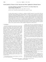
GRAPHICAL ABSTRACT
Title: Cross-linkable Polymers Containing Triple Bond Backbone and Their Application in
Cheol Lee, Sang Kyu Lee, Sang-Jin Moon, and Won Suk Shin*
Three
novel
triple
bond
containing
10
polymers, named A-A, D-A and D-D, were
and
two
of
them
were
investigated their photocrosslikability, as
well as their application as buffer layers in
OPV. The PSC device with A-A polymer
buffer layer exhibited the best average PCE
-2
designed
8
6
4
Ar1
Ag
MoOx
Ar2
Active Reference
layer
2
ZnO
ITO
0
A-A, UV 0 min
A-A, UV 5min
Glass
of 3.10% after 5 min UV exposure, caused
0.0
by the improved FF compare to the device
with
bare
ZnO
layer.
Our
0.1
0.2
0.3
0.4
0.5
0.6
Voltage(V)
research
introduced potential candidates for new photocrosslinkable materials which has solvent
resistance and hydrophobic nature, and can be used in solution processed multilayer of organic
electronic devices
RSC Advances Accepted Manuscript
Authors: Thi Thu Trang Bui, Sangheon Park, Muhammad Jahandar, Chang Eun Song, Jong-
Current Density(mA cm )
Published on 10 June 2016. Downloaded by Weizmann Institute of Science on 12/06/2016 09:19:09.
Photovoltaic Devices