DSpace at VNU: Study of the Resistive Switching Effect in Chromium Oxide Thin Films by Use of Conductive Atomic Force Microscopy
Bạn đang xem bản rút gọn của tài liệu. Xem và tải ngay bản đầy đủ của tài liệu tại đây (1.45 MB, 6 trang )
Journal of ELECTRONIC MATERIALS
DOI: 10.1007/s11664-015-3889-z
Ó 2015 The Minerals, Metals & Materials Society
Study of the Resistive Switching Effect in Chromium Oxide Thin
Films by Use of Conductive Atomic Force Microscopy
KIM NGOC PHAM,1 MINSU CHOI,2 CAO VINH TRAN,3
TRUNG DO NGUYEN,1 VAN HIEU LE,1 TAEKJIB CHOI,4
JAICHAN LEE,2 and BACH THANG PHAN1,3,5
1.—Faculty of Materials Science, University of Science, Vietnam National University, Ho Chi
Minh City, Vietnam. 2.—School of Advanced Materials Science and Engineering, Sungkyunkwan
University, Suwon, Republic of Korea. 3.—Laboratory of Advanced Materials, University of Science, Vietnam National University, Ho Chi Minh City, Vietnam. 4.—Hybrid Materials Research
Center and Faculty/Institute of Nanotechnology and Advanced Materials Engineering, Sejong
University, Seoul, Republic of Korea. 5.—e-mail:
Reversible resistive switching of Cr2O3 films was studied by use of conductive
atomic force microscopy. Resistive switching in Cr2O3 films occurs as a result
of Ag filament paths formed during electrochemical redox reactions. A large
memory density of 100 Tbit/sq. inch was achieved with a small filament
diameter of 2.9 nm under the action of a compliance current of 10 nA. A fast
switching speed of 10 ns, high scalability, and low set/reset currents suggest
that Cr2O3-based resistive memory is suitable for nanoscale devices.
Key words: Chromium oxide, resistive switching, electrochemical redox
reactions, C-AFM, Ag filament
Recent research has shown that resistance
switching random access memory (ReRAM) is a
promising candidate for nanoscale nonvolatile memory applications. Oxide-based ReRAM structures
exploit the functionality of capacitor structures in
which the oxide materials, for example perovskite
(Cr-doped SrTiO3, Cr-doped SrZrO3, Pr0.7Ca0.3MnO3,
etc.),1–8 chalcogenide materials (GeSbTe),9 transition
metal oxides (TMOs), or binary oxides (NiO, TiO2,
CuOx, HfO2, ZrOx, ZnO, Nb2O5, Al2O3, WOx,
CrOx)10–18 are sandwiched between two metal electrodes. Choosing a material compatible with CMOS
processes is a crucial challenge in current research on
ReRAM. Among the different materials used, TMOs
have the major advantages of simple fabrication and
compatibility with CMOS processes.19–22 We have
focused on correlation of the switching behavior of
oxide films (SrTiO3, ZnO, TiO2, WO3 and CrOx) with
crystallinity and electrode material.5–8,14–17 From the
perspective of application, the basic requirement for
next-generation non-volatile memory is high scalability. Because it has recently been shown that
switchable conducting nano-filaments may have
(Received March 12, 2015; accepted June 4, 2015)
potential for realizing high-density devices, filamentary switching in nanoscale devices has attracted
much attention.20–23 Further physical insights into
geometrical aspects of conducting filaments, for
example their number, size, and location, can be
obtained by use of conductive atomic force microscopy
(C-AFM). Recently, we reported the switching
behavior of CrOx thin films, and that the mechanism
of switching was an electrochemical redox reaction.17
To complement previous work, in this paper we
report the progressive appearance of conducting filaments in CrOx thin films during resistance switching, studied by use of C-AFM.
Silver and chromium oxide films were fabricated,
by use of the DC sputtering technique at room
temperature, from metallic Ag and Cr targets, on
commercial Pt substrates. Deposition of 100-nmthick chromium oxides was performed in a gaseous
mixture of 6% oxygen in argon with the total pressure kept at 7 9 10À3 Torr. During deposition of the
Ag top electrode, in an argon environment at
7 9 10À3 Torr, a mask was used for top electrode
patterning. X-ray photoelectron spectroscopy (XPS)
was used to investigate the chemical state of the
films. Current–voltage (I–V) measurements were
obtained by use of a semiconductor-characterization
system (Keithley 4200 SCS) and probe station. The
Pham, Choi, Tran, Nguyen, Hieu Le, Choi, Lee, and Phan
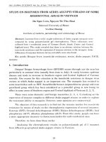
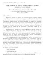
Fig. 1. XPS spectra of the (a) Cr 2p3/2 and (b) O 1s core levels for
chromium oxide film.
voltage profile for I–V measurements was 0 V fi
À (+)Vmax fi 0 V fi + (À)Vmax fi 0 V. The Pt
bottom electrode was biased and the top electrode
was grounded. For C-AFM measurement, 10-nmthick chromium oxide was deposited on the Ag
bottom electrode. C-AFM measurements were conducted under ambient conditions by use of a Veeco
Dimension D3100 atomic force microscope with Pt
conductive tips as the top electrode.
Figure 1 shows the Cr 2p and O 1s core level XPS
spectra of CrOx films prepared at room temperature.
As shown in Fig. 1a, the Cr 2p3/2 core level spectrum
was deconvolved into three peaks with binding
energies of 576.1 eV, 577.5 eV, and 579.2 eV. The
576.1 eV-peak was attributed to Cr3+ in Cr2O3. The
two peaks at higher binding energies ($577.5 eV
and 579.2 eV) were assigned to Cr3+ and Cr6+, corresponding toCrO(OH)/Cr(OH)3 and CrO3, respectively. The relative amounts of Cr2O3, CrO(OH)/
Cr(OH)3, and CrO3, estimated by Gaussian–Lorentzian curve fitting, were 51.63%, 36.7%, and
11.5%, respectively. It is clearly apparent that the
Cr2O3 phase is predominant.
Deconvolution of the O 1s spectrum in Fig. 1b
resulted in three peaks centered at 530.2 eV,
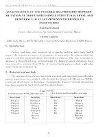
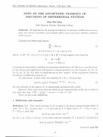
Fig. 2. (a) Typical bipolar current–voltage characteristics of Ag/
Cr2O3/Pt structures and (b) endurance of Ag/Cr2O3/Pt devices under
the action of cycling pulses 10 ns wide.
532 eV, and 533.6 eV. The highest-intensity peak of
530.2 eV was assigned to lattice oxygen or a stoichiometric Cr2O3 phase. The lower-intensity peak at
higher binding energy was assigned to non-lattice
oxygen or non-stoichiometric phases. The binding
energy of 532 eV corresponds to absorbed oxygen
species (OÀ,O2À
2 ) on the surface of the film. The
lowest-intensity peak centered at 533.6 eV was
attributed to the presence of CrO(OH)/Cr(OH)3
phases in the CrOx film.
Figure 2 shows typical current–voltage characteristics of the Ag/100 nm-Cr2O3/Pt structure
investigated by use of a dc sweeping voltage with
electric pulses applied to Pt bottom electrode. As is
apparent from Fig. 2a, the pristine Ag/Cr2O3/Pt
structure has a high-resistance state (HRS). A
negative bias voltage applied to the Pt bottom electrode switched the structure to the low-resistance
state (LRS). Subsequently, on sweeping the positive
voltage up to +2 V, the structure was converted
back to the HRS. The hysteresis I–V curve follows bipolar resistance switching. The resistance
switching described above can also realized by
applying electric pulses with a width of 10 ns, as
Study of the Resistive Switching Effect in Chromium Oxide Thin Films by Use of Conductive
Atomic Force Microscopy
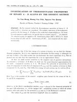
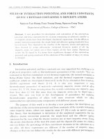
Fig. 3. (a) Schematic diagram of the device used for C-AFM measurements. (b) Local I–V hysteresis curve obtained by C-AFM at a compliance
current of 10 nA. (c–f) Current mapping images in 2D and 3D for the writing and erasing processes for Cr2O3 thin films. (g) Statistical distribution
of the size of silver conductive filaments during the writing process at a compliance current of 10 nA.
shown in Fig. 2b. The switching was a relatively
fast process. Therefore, RRAMs as universal memories should match DRAMs in terms of switching
speed (DRAM write/erase time $10 ns/10 ns). The
resistance ratio of the HRS and LRS is >30 and
both the HRS and LRS are quite stable after 103
cycles, indicative of good endurance of the Ag/Cr2O3/
Pt structure.
Because the I–V curve of the LRS on the log–log
scale is indicative of a linear relationship between
current and voltage (not shown here), in addition to
the nature of the electrodes, a reactive Ag electrode
Pham, Choi, Tran, Nguyen, Hieu Le, Choi, Lee, and Phan
Fig. 3. continued.
and an inert Pt electrode, and the switching direction, it is suggested that the mechanism of switching of Cr2O3 thin films involves electrochemical
redox reactions, which are explained as follows. On
application of a negative voltage to the Pt bottom
electrode (positive voltage to the Ag top electrode),
an electrochemical reaction occurs at the anode
(Ag), which oxidizes the Ag metal atoms to Ag ions.
These Ag+ ions start from the top interface and drift
through the Cr2O3 films to connect with the bottom
electrode. At the Pt cathode, electrochemical
reduction and electro-crystallization of Ag occur.
This electro-crystallization process results in the
formation of an Ag filament, which grows toward
the Ag electrode. As a result, the Ag filaments grow
and connect the Ag top electrode, leading to HRS to
LRS switching. To reset the cell, a positive voltage is
applied to the Pt bottom electrode (negative
switching voltage to the Ag top electrode), which
leads to dissolution of the Ag filament, and LRS to
HRS switching occurs.
XPS analysis shows the presence of oxygen
vacancies V2+
o in the Cr2O3 thin films. These oxygen
vacancies can affect resistive switching of the Cr2O3
thin films. To check the effect of these oxygen
vacancies and of the Ag filaments, we replaced Ag
by Ti as top electrode. The Ti/Cr2O3/Pt structure
had no resistive switching behavior. Therefore, the
oxygen vacancies do not make a major contribution,
if any, to the switching mechanisms. It can again be
concluded that Ag filament paths mediated by
electrochemical redox reactions are responsible for
resistive switching in the Cr2O3 thin films.
Local I–V hysteresis measurements for the Ag/
10 nm-Cr2O3/Pt structure were conducted by use of
C-AFM. A conductive Pt-coated C-AFM tip was used
as the top electrode, as shown schematically in
Fig. 3a. The voltage was applied to the bottom
electrode during the C-AFM scan. The sweeping
voltage followed the sequence 0 fi + 2 V fi
0 fi À2 V fi 0, repeatedly. A compliance current
was used during measurements, to protect the
C-AFM probe and the structure. Hysteresis in the
I–V curve at a compliance current Ic = 10 nA is
clearly observed in Fig. 3b. In process 1, the initial
HRS was switched to the LRS at an applied voltage
(Vset) of approximately +1.7 V. In the subsequent
voltage sweep, process 3, a negatively applied voltage (Vreset) of À1.5 V resulted in reversion of the
structure back to the HRS. It is noted that the large
set and reset currents hinder the application of
TMOs to integrated RRAM devices. However, our
Ag/Cr2O3/Pt structure can switch repeatedly with
low set and reset currents of 10 nA, leading to very
low power consumption.
Conductivity mapping results for the writing and
erasing processes with Cr2O3 films are shown in 2D
and 3D images in Fig. 3c–f. In the writing process, a
positive voltage of +0.5 V was applied to the Ag
bottom electrode leading to the random presence of
bright spots on a dark background; these represent
conducting spots or multiple filaments. In the
erasing process, application of a negative voltage of
À0.5 V to the Ag bottom electrode, deletes the current spots completely, resulting in a uniform dark
background. The presence of the conducting spots
qualitatively confirms the filament model of resistive switching.
Figure 3g shows the statistical distribution of the
size of conductive filaments obtained from the
writing process at a compliance current of 10 nA.
The lateral size of the bright spots ranged from
2.9 nm to 30 nm. The spot shape also indicates the
spots contain multiple filaments. The predominant
size is <15 nm. The small size of the filaments
suggests that memory cell size can be scaled down to
nanometers.
The ability to store multiple resistance states in a
single memory cell is one of the most important
requirements for non-volatile RRAM, because this
can enable dramatic enhancement of memory density. Compliance current dependence should also be
tested, because different compliance currents are
believed to result in multiple resistance states or
multiple logical bits.
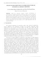
Local I–V hysteresis, current mapping results,
and the statistical distribution of filament sizes
obtained from the writing process at a compliance
current of 500 nA are shown in Fig. 4a–d. In comparison with results obtained by use of a compliance
current of 10 nA, conductivity mapping shows conducting spots with a greater density in the Cr2O3
films. The lateral size of the bright spots ranged
from 8.8 nm to 100 nm, with the size predominantly
below 20 nm. The statistical distribution of filament
sizes shows the minimum diameter of the filaments
in the Cr2O3 are 2.9 nm and 8.8 nm for Ic = 10 nA
and 500 nA, respectively. A larger physical diameter is induced by use of the larger compliance current; this results in a lower resistance. The different
compliance currents clearly indicate that filaments
with different resistances are formed. Therefore,
Study of the Resistive Switching Effect in Chromium Oxide Thin Films by Use of Conductive
Atomic Force Microscopy
Fig. 4. (a) Local current behavior investigated by C-AFM. (b, c) Current mapping images in 2D and 3D for the writing process. (d) Statistical
distribution of the size of conductive filaments for a compliance current of 500 nA.
controlling the compliance current modulates the
size of the filament and thus the resistance. In
addition, the corresponding memory densities are
100 Tbit/sq and 10.6 Tbit/sq for filament diameters
of 2.9 nm and 8.8 nm, respectively.
In this study, reversible resistive switching of
Cr2O3 films was performed by use of C-AFM. Filament-controlled bipolar resistance switching were
clearly apparent from local I–V hysteresis, conductivity, and current mapping. Our study revealed the
correlation between compliance current and filament size, and the multilevel capability and memory density of Cr2O3-based RRAM devices. The
small compliance current results in small filament
sizes, higher memory density, and low power consumption, suggesting that memory cell size can be
scaled down to tens of nanometers.
ACKNOWLEDGEMENTS
This work was funded by the National Foundation
of Science and Technology Development of Vietnam
(NAFOSTED—103.02-2012.50), The Exchange Fellowship Programme under ASEAN-ROK Academic
Exchange Programme 2014, and the Basic Science
Research Program through the National Research
Foundation of Korea (2009-0092809).
REFERENCES
1. A. Beck, J.U. Bednorz, C. Gerber, Ch. Rossel, and D.
Windmer, Appl. Phys. Lett. 77, 139 (2000).
2. S.Q. Liu, N.J. Wii, and A. Ignatiev, Appl. Phys. Lett. 76,
2749 (2000).
3. Y. Watanabe, J.G. Bednorz, A. Bietsch, C. Gerber, D.
Widmer, A. Beck, and S.J. Wind, Appl. Phys. Lett. 78, 3738
(2001).
4. R. Waser and M. Aono, Nat. Mater. 6, 833 (2007).
5. B.T. Phan and J. Lee, Appl. Phys. Lett. 93, 222906 (2008).
6. B.T. Phan and J. Lee, Appl. Phys. Lett. 94, 232102 (2009).
7. B.T. Phan, N.C. Kim, and J. Lee, J. Kor. Phys. Soc. 54, 873
(2009).
8. B.T. Phan, T. Choi, A. Romanenko, and J. Lee, Solid-State
Electronics. 75, 43 (2012).
9. Y-C. Chen, C.F. Chen, C.T. Chen, J.Y. Yu, S. Wu, S.L. Lung,
R. Liu, and C-Y. Lu, IEDM Tech. Dig. (2003).
10. B.J. Choi, D.S. Jeong, S.K. Kim, S. Choi, J.H. Oh, C. Rohde,
H.J. Kim, C.S. Hwang, K. Szot, R. Waser, B. Reichenberg,
and S. Tiedke, J. Appl. Phys. 98, 033715 (2005).
Pham, Choi, Tran, Nguyen, Hieu Le, Choi, Lee, and Phan
11. K. Jung, H. Seo, Y. Kim, H. Im, J.P. Hong, J.W. Park, and
J.K. Lee, Appl. Phys. Lett. 90, 052104 (2007).
12. A. Chen, S. Haddad, Y.C. Wu, Z. Lan, T.N. Fang, and S.
Kaza, Appl. Phys. Lett. 91, 123517 (2007).
13. C.Y. Lin, C.Y. Wu, C. Hu, and T.Y. Tseng, J. Electrochem.
Soc. 154, G189 (2007).
14. T. Le, H.C.S. Tran, V.H. Le, T. Tran, C.V. Tran, T.T. Vo,
M.C. Dang, S.S. Kim, J. Lee, and B.T. Phan, J. Korean Phys.
Soc. 60, 1087 (2012).
15. K.N. Pham, T.D. Nguyen, T.K.H. Ta, K.L.D. Thuy, V.H. Le,
D.P. Pham, C.V. Tran, D. Mott, S. Maenosono, S.S. Kim, J.
Lee, D.T. Pham, and B.T. Phan, Eur. Phys. J. Appl. Phys.
64, 30102 (2013).
16. J.B. Park, K.P. Biju, S.J. Jung, W.T. Lee, J.M. Lee, S.H.
Kim, S.S. Park, J.H. Shin, and H.S. Hwang, IEEE Electron
Device Lett. 32, 476 (2011).
17. N.K. Pham, D.T. Nguyen, B.T.T. Dao, K.T.H. Ta, V.C. Tran,
V.H. Nguyen, S.S. Kim, S. Maenosono, and T.B. Phan,
J. Electron. Mater. 43, 2747 (2014).
18. T.B.T. Dao, K.N. Pham, Y.L. Cheng, S.S. Kim, and B.T.
Phan, Curr. Appl. Phys. 14, 1707 (2014).
19. J.W. Seo, Doctor Thesis, Transparent resistive random access memory for transparent electronics, Korean Advanced
Institute of Science and Technology (2011).
20. S.Z. Rahaman, S. Maikap, T.C. Tien, H.Y. Lee, W.S. Chen, F.T.
Chen, M.J. Kao, and M.J. Tsai, Nanoscale Res. Lett. 7, 345 (2012).
21. Q. Liu, J. Sun, H.B. Lv, S.B. Long, K.B. Yin, N. Wan, Y.T.
Li, L.T. Sun, and M. Liu, Adv. Mater. 24, 1844 (2012).
22. A. Prakash, S. Maikap, H.C. Chiu, T.C. Tien, and C.S. Lai,
Nanoscale Res. Lett. 8, 288 (2013).
23. A.A. Sharma, M. Noman, M. Abdelmoula, M. Skowronski,
and J.A. Bain, Adv. Funct. Mater. 24, 5522 (2014).