Duration Calculus with Iteration and Software Graph in an Embedded Control Application
Bạn đang xem bản rút gọn của tài liệu. Xem và tải ngay bản đầy đủ của tài liệu tại đây (243.1 KB, 11 trang )
Duration Calculus with Iteration and Software Graph in
an Embedded Control Application
1
Pham Tran Nhu , Nguyen Van Truong
2
1
Institute of Information Technology, P.O. Box A3, 18 Hoang Quoc Viet, Hanoi, Vietnam
2
Thai Nguyen University of Education, Luong Ngoc Quyen Road, Thai Nguyen, VietNam
Abstract. We present a syntactical approach given in a formal design technique
for combining Duration Calculus with Iteration (DC*) and software graph (sgraph). The technique is used for designing real-time embedded systems.
Integrating these two formal methods to work together in the spirit of
hardware/software co-design may allow co-operating their strengths, while
alleviating some of their weaknesses.
Keywords: DC*, s-graph, formal methods.
1 Introduction
Each of the software methods has typical advantages and disadvantages. For example,
automatic verification methods are desirable since they are exhaustive and require
minimal human intervention; however, the effectiveness of such methods decreases
rapidly with the size of the checked systems. Integrating formal methods to work
together may allow combining their strengths, while alleviating some of their
weaknesses [5].
Duration Calculus (DC), a logic based on Interval Temporal Logic, is powerful
enough for specifying and reasoning about the behavior of real-time systems in
continuous time model. It has been used successfully in many case studies as
specification language. Duration Calculus with Iteration (DC*) is an extension of DC
with the iteration operator to play the role of interface between DC and timed
automata model. However, the design technique using DC* can be solved
successfully only under some assumptions about the behavior of the environments
and the relationship between continuous variables and discrete ones. This idea leads
to the natural choice of combining DC* with other methods to evaluate and estimate
exactly environment and system restrictions.
In this paper, we present a syntactical approach for combining DC* and s-graph
from a formal specification of the requirements of real-time systems. The main idea is
to model the discretization at the state level by introducing the discrete states
approximating the continuous ones, and then derive a specification of the system over
discrete states. Moreover, the approach provides a logical framework that can handle
effectively consumptions about the time latency in designing steps, which were not
solved in many case studies using DC*, see e.g. [1, 2, 13].
The remaining of the paper is organized as follows. In Section 2 we give a brief
summary of DC* and s-graph. The combination technique is presented in Section 3.
Section 4 concludes the paper.
2 DC* and S - Graph
It is not the purpose of this paper to give a complete description of these formalisms
but just a simple introduction to make easier the understanding of the following.
Readers may find more details in [1, 12] about DC* and in [7] about s-graph.
2.1 DC*
A language for DC* is built starting from the following sets of symbols: a set of
constant symbols {a, b, c,...}, a set of individual variables {x, y, z,...}, a set of state
variables {P, Q,...}, a set of temporal variables {u, v,...}, a set of function symbols {f,
g,...}, a set of relation symbols {R, U,...}, and a set of temporal propositional letters
{A, B,...}.
A DC* language definition is essentially that of the sets of state expressions S,
terms t and formulae of the language. These sets can be defined by the following
BNFs:
S ≙0PSS S
t ≙cxu∫
Sf(t,..., t)
≙AR (t,..., t)( )(◠)(*)x
+
A state variable P is interpreted as a function I(P): IR {0,1} (a state). I(P)(t) =
1 means that state P is present at time t, and I(P)(t) = 0 means that state P is not
present at time t.
We assume that a state has finite variability in any finite time interval. A state
expression is interpreted as a function, which is defined by the interpretations for the
state variables and boolean operators.
For an arbitrary state expression S , its duration is denoted by ∫
S . Given an
interpretation I of the state variables and an interval, duration ∫
S is interpreted as the
accumulated length of time within the interval at which S is present. So for any
interval [t, t’], the interpretation I(∫
S)([t, t’]) is defined as
t'
t I(S)(t)dt.
A formula is satisfied by an interpretation in an interval [t, t’] when it evaluates
to true for that interpretation over that time interval. This is written as I,[t, t'] ⊨.
Given an interpretation I, a formula ◠’ is true for [t, t’’] if there exists a t’ such
that t t’t’’ and and ’ are true for [t, t’] and [t’, t’’], respectively.
We consider the following abbreviations: 1 ≙0, ≙∫
1,
S≙(∫
S=
) (> 0),
◊≙(true◠◠true), □≙◊, k ≙ ◠...◠ (k times, for k > 0).
The proof system for DC* consists of a complete Hilbert-style proof system for
first order logic (cf. e.g. [8]), axioms and rules for interval logic, Duration Calculus
axioms and rules and axioms about iteration (cf. e.g. [12]).
The proof system of DC* is complete for sentences where iteration is allowed only
for a restricted class of formulas called simple.
Definition 1 Simple DC* formulas are defined inductively by the following BNF
≙ = 0
S a
a( )()(◠)*
Definition 2 Given a simple DC* formula , we define a simple DC* formula
PREF() as follows.
1. PREF (
S) ≙
S
*
2. PREF (a ) ≙0
3. PREF (a) ≙a
4. PREF (’) ≙ PREF ()
PREF (’)
5. PREF ( ’) ≙ PREF () PREF (’)
6. PREF( ◠ ’) ≙ PREF ( ) (
◠PREF(’))
7. PREF ( *) ≙ * ◠PREF ( )
Intuitively, PREF() is a simple DC* formula that holds for all prefixes of an interval
that validates .
A simple DC* formula denotes exactly a Timed Regular Expression and therefore
a time automaton. Moreover, it has an interesting property that it is decidable [1].
2.2 S-graph
Definition 3 An s-graph G is a directed acyclic graph with one source and one sink.
Its vertex set V contains four types of vertices: BEGIN, END, TEST and ASSIGN.
The source has type BEGIN, the sink has type END. All other vertices are of type
TEST or ASSIGN. Each TEST vertex v has two children true(v) end false(v). Each
BEGIN or ASSIGN vertex u has one child next(u) only. Any non-source vertex can
have one or more parents. An s-graph is associated with a set of m input and l out put
variables z1,..., zm+l, ranging over finite domains D(z1),..., D(zm+l), respectively.
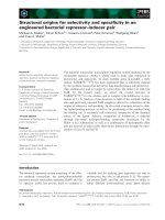
Fig. 1. A simple s-graph
The s-graph model resembles order binary decision diagrams (OBDD) [7], which
based on a decomposition of Boolean function called the Shannon expansion. A
function f can be decomposed in terms of a variable as follows.
f = x. fx=1 + x. f x= 0
The manipulation of s-graph is also similar to that of OBDD. It means that, one can
operate logic operators on variables (AND, OR and NOT). Fig. 1 illustrates a simple
example of an s-graph.
Each ASSIGN vertex v is labeled with an output variable zv, and a D(zv)-valued
function av(z1,..., zm+l). In the graphical representation of s-graphs, we label such a
vertex with zv:= av(z1,..., zm+l) to indicate the meaning of ASSIGN.
Each TEST vertex v is labeled with a predicate pv(z1,..., zm+l), whose truth value
determines which child will be executed.
The evaluation of the multioutput function computed by an s-graph with BEGIN
node v, m input variables and l output variables.
In an s-graph, we present the transition function as a composition of the following:
- Set T of tests on input and state variables.
- Set A of actions, which can be either output emissions or assignments to states
variables.
- The reactive function mapping subsets of T to subsets of A, represented by its
|T| + |A|
characteristic function F: {0, 1}
{0, 1}.
For example, in the Figure, tests are present_c and a = ?c; actions are a’:= a, a’:=
0, a’:= a + 1 and emit_y; and the reactive function is:
present_c
0
0
1
1
a=?c;
0
1
0
1
a’:= a
1
1
0
0
a’:= 0,
0
0
0
1
a’:= a+1
0
0
1
0
emit_y
0
0
0
1
Conceptually, the transition function is executed in three phases:
- Tests are evaluated to determine the values of input variables of the reactive
function.
- The s-graph of the reactive function is evaluated to determine the values of its
output variables.
- Actions corresponding to output variables are executed.
S-graph is built recursively starting from reactive function based on the Shannon
decomposition ([16]).
Theoretically, dynamic calculation of software performance can be done with
realistic inputs. Both the structure of the synthesized code and the architecture of the
target system can be considered. Static calculation, useful for example for worst case
execution time analysis, can be done by using graph traversal algorithms. Assume that
E is the number of edges in the s-graph and N the number of nodes. The minimumcost path based on Dijkstra's shortest path algorithm from the BEGIN to END vertex
of the s-graph is O(ElogN)).
3 Combining the methods
3.1 The technique description
The combination process can be formalized by consecutive steps. Firstly, a state
variables model of the system should be defined. The state variables model comprises
continuous state variables and discrete state variables. Secondly, the requirement of
the system is formalized as a DC formula Req over continuous state variables. A
design decision must be established so that the requirement of the system will be met
and refined into a detailed design Des over continuous state variables such that A
⊦Des Req, where A stands for some assumptions about the behavior of the
environment and the relationship between continuous state variables. Finally, the
discrete step follows. We approximate continuous state variables by discrete ones and
formalize the relationship between them based on the general behavior of the sensors
and actuators. The control requirement is derived from the detailed design and refined
into a simple DC* formula Cont over discrete state variables such that Ac⊦Cont
Des, where Ac stands for some assumptions about the behavior of the environment and
the relationship between continuous state variables, and relationship between discrete
state variables and continuous ones. The assumptions in the last two phases include
ones about time latency of hardware and software, which were computed and
estimated exactly by the corresponding s-graph. The discrete formula Cont is the
formal specification of the controller.
3.2 A case study: designing a single lift control system
We will illustrate the technique in the remaining of this section with a simple case
study. The readers are referred to [2, 13] for more details on the designing steps,
Discrete Interface, Refinement and Verification Rules.
We now define three concepts for formalizing the relationship between continuous
state variables and discrete ones.
Definition 4 (Stability) Given a state variable s and a positive real number , we say
s is - stable iff the following formula is satisfied by any interval
-stable(s) ≙□(
s◠
s◠
s
s◠ (
s> ) ◠
s)
Definition 5 (Control state) Given two state variables r and s, and a non-negative
real number , we say r - controls s iff the following formula is satisfied by any
interval
r ⊲s ≙□(
r> ()◠
s)
Definition 6 (Observation state) Given two state variables r and s, and a nonnegative real number
, we say r - observes s iff the following formula is satisfied by
any interval
r
s ≙(s ⊲r) (s⊲r)
3.2.1 Problem domain description
The logical control of a lift system studied in this paper consists of a simple, single lift
system. It allows movement of a single lift cage between a finite numbers of floors.
Components: a lift cage with send buttons, one for each floor; a motor; n + 1 floors,
each with a floor door, a call button and a close button; sensors and actuators; a
controller.
Attributes:
- The lift cage is either stopped at floor j for j lying between 0 and n inclusive, or is
moving up (or down) between floors i and i +1 (i and i - 1), for i lying between 0
and n - 1 (n and 1).
- A floor door is either open or closed.
- The motor is either running up (or down) or is stopped.
- The motor, when running, runs at a constant speed - which causes the lift cage to
move between immediately neighboring floors in tm time units.
Events:
- A send button is pressed for floor k, for k = 0,..., n.
- A call button on floor k is pressed, for k = 0,..., n.
- A close button is pressed for the door at floor k, for k = 0,..., n.
- The opening (and closing) of floor doors.
- The starting and stopping of the motor - implying the same for the cage.
Procedure:
- Servicing a floor k means that a send button is pressed for floor k, or a call button
on floor k is pressed or the lift cage is running upwardly or downwardly (towards
floor k).
- There is a request on floor j, means that a call or a send button at floor j is pressed,
iff there does not exist any services of floors and the floor door is closed; or a close
button at floor j is pressed when the floor door is open. This implies that the lift
system services floors successively. This dogma makes our design simple.
Invariants:
- There are at least two floors (a component invariant).
- The cage has exactly one send button for each floor (a component invariant).
- Pressing a call button at floor i or pressing a send button for floor i causes the lift
to service that floor within ts time units (a procedural, functional invariant).
- A floor door may only be open if the lift cage is at that floor (a component safety
invariant).
- The floor door is open for at least t0 time units and at most tmax time units.
The lift system presented in this paper shall be monitored and controlled by a
controller that shall respect the components, handle the events, and satisfy the usual
procedures and invariants enumerated above.
3.2.2 Formalizing the requirements of the system
We introduce the following continuous state variables: variable c i holds if the call
button on floor i is pressed, variable si holds if the send button for floor i is pressed,
variable di holds if the door at floor i is open, and variable fi holds if the lift is at floor
i, for i ranges over interval [0,..., n]; variable motor holds if motor is on (and this
makes the lift cage move); variable closei holds if the close button on floor i is
pressed.
The requirements of the system are defined by Req ≙□(SafetyReq FunctReq)
The safety property for the lift control system is: for every floor, the door must
only be opened if the lift is at that floor. This is equivalent to stating that “if the lift is
not at floor i, then door i must be closed”.
SafetyReq ≙
di
fi
The function requirement is the following conjunction
FunctReq ≙F1 F2 F3
Pressing a send button causes the lift to service the corresponding floor within ts
time units.
F1 ≙
si≙ true ts(ts◠
di◠ true)
This requirement states that for every observation interval for which si holds
initially, i.e. the send button for the i’th floor is pressed, either the interval is shorter
than or equal to ts or it may be divided into three subintervals where the first lasts at
most ts , in the second the door at floor i is opened, and a final subinterval which is
unconstrained.
A similar condition must hold when pressing a call button: pressing a call button
causes the lift to service the corresponding floor within ts time units.
F2 ≙
ci◠ true ts (ts ◠
di◠ true)
The system must guarantee that when a floor is serviced, the door is open for at
least t0 time units and at most tmax time units.
F3 ≙ (
di◠
di◠
di t0) (
di tmax)
We now present a design decision, which implements the requirements.
3.2.3 Design decision
We define the design decision by the predicate Des
Des ≙ □(D1 D2 D3 D4 D5 D6 D7)
The following formula is derived directly from the assumptions of the behavior of
the system.
D 1 ≙ ((= a
si c i)◠(= b (
di◠
di))
(= a)◠(b
(si ci sj cj))◠ true)
(close i di)
(c i di)
(ci si)
(si di)
(c i dj)
(ci cj)
(c i sj)
(si sj)
(si dj)
If for every interval for which a send button for floor i is pressed initially, and the
lift is at floor j, and j i, then the interval may be divided into three subintervals. The
first lasts at most time units, in the second the motor is on, and an unconstrained
final subinterval; in the condition of i = j, then the door at floor i must be opened
within time units, where stands for a response time of the system. A similar
condition must hold when pressing a call button at floor i.
D2 ≙
(si ci) fj◠ true ()◠
motor◠ true
D3 ≙
(si ci) fi◠ true () ◠
di◠ true
If a send button for floor i is pressed while lift is at floor j, the lift may reach the
destination floor and then the motor is off and the door at the floor is opened within
time units. A similar condition must hold when pressing a call button at floor i.
D4 ≙(
(si c i) fj◠ true
()◠= |i - j|t m◠
(◠
di)
fi◠ true)
(
(si ci) fj◠ true
()◠= |i - j|t m ◠
(◠
motor)
fi◠ true)
If the close button at floor i is pressed it may make the door at the floor open
within time units.
D5 ≙
close i◠ true ()◠
di◠ true
Two following formulas will help satisfy the requirement of the maximum and
minimum time units for which a door is open.
D6 ≙
di◠
di◠ true
di◠< t0◠
closei◠ true
D7≙ (
ditmax - 1 tmax) ◠ true
di◠
di◠ true
Initially the lift is idle at the ground floor with the doors close, motor stops, and no
requests for the lift.
Init ≙
motor f0 di si ci closei◠ true
The maximum time it may take to service a floor corresponds to the time it takes to
move across n + 1 floors and the response time it takes to open doors.
A1 ≙ (ts (n +1) tm + 2)
The following formula is derived directly from the attribute of the motor as
described in Section 3.2.1
A2 ≙
(si ci) fj◠ true ◠= |i - j|t m ◠
fi◠ true
We assume that the response time is small enough in order to the lift, having
reached the destination floor, can be at the floor within at least time units while the
motor is still running.
A3 ≙
fi◠
fi motor◠ true
fi◠
fi◠ true
A4 ≙ (t0 + + 1 tmax)
Let A ≙Init A1 A 2 A3 A4
3.2.4 Discrete design
For any continuous state variable s, let sc be the discrete state variable used by the
controller to observe s via the sensors. Then the relationships between continuous
f ,
state variables and discrete state ones are formalised as following formulas: fic
i
c ic
c , dic
d , sic
s , and closeic
close i, where is the sampling step.
i
i
i
Let Dopeni, Dclosei, Mon, and Moff be discrete state variables, which hold when
the controller requests the actuators to open the door at floor i, close the door at floor
i, start the motor, and stop the motor, respectively. The relationship between them and
the continuous state variables di and motor are expressed by Dopeni ⊲ di, Dclosei
⊲di, Mon ⊲motor, and Moff ⊲motor, where stands for the response time of
the plant via the actuators. Besides, we also introduce a symbol as one described
above.
Let 1 ≙(
(c icsic) fjc Mon=
) ◠ (|i - j|tm + |i - j|tm )◠
Moff
2 ≙ (
(cic sic ) fjc Mon=
) ◠ (|i - j| tm + |i - j|tm )◠
Dopeni
3 ≙
(cic sic ) fic Dopeni(=
)
1 ≙ (t0 - ) ◠
closeic Dclosei
2 ≙ (tmax - - 1 tmax - ) ◠
Dclosei
1 ≙(
(c icsic) fic ◠(+ |i - j| tm ) ◠
c icsiccjc sjc)
2 ≙
(c ic djc )
(cic cjc )
(c ic sjc )
(sic sjc )
(sic djc )
(close ic dic )
(c ic d ic)
(cic sic)
(sic dic )
≙
c ic sic
* ◠ (( 12 ) 3◠1 2)*
≙
c ic sic
*
c ic sic ◠ ((12) 3◠1 2 )*
A discrete design for the controller is defined as following formula
Cont ≙ (* ◠PREF (*)) 1 2
Let A c ≙ A (fic
f ) (c ic
c ) (dic
d ) (sic
s ) (closeic
closei)
i
i
i
i
(Dopeni ⊲d i) (Dclosei ⊲di) (Mon ⊲motor) (Moff ⊲motor)
( + ) (
Dopeni ) (
Dclosei )
The following Theorem establishes the correctness of the discrete design, under the
assumption about the relationship between discrete state variables and continuous
ones, and the behavior of the environment.
Theorem 1 Ac⊦Cont Des (Proof. See [13]).
In the design process, we must choose and satisfying the hardware and software
latencies, which were evaluated and estimated easily by using s-graph. We have
implemented s-graph in C language and tested it successfully. Conceptually, the input
for initial s-graph need not always be a function but could also be a relation. In the
paper, we consider that s-graph comes at the end of the technique design simply to fill
in the estimated values for parameters of DC*. The readers are referred to [2] for
details on how to write a real-time program for the controller and verify its
correctness w.r.t. the formula Cont using extended Hoare triples.
4 Conclusion
We consider DC* as specification language to reason about the design of the system,
which has been used successfully in many case studies, see e.g. [1, 2, 13]. However,
these had not mentioned about how to choose assumptions about environment,
especially about time latency. We used s-graph associated with DC* to resolve the
problem.
Using the technique will make our system design move closer to real world
compares to one given in [10], and it is useful for programmers to implement it in
some programming languages. Besides, it is not difficult to prove the correctness of
the design of the system by using the technique. In general, we just have considered
the system with simple requirements and the dogmatic assumption.
In the future, we will use the technique to design more complex and practical
systems with optimized processes of s-graph combining with DC*. Moreover, we are
planning to integrate DC* formal language with Co-design Finite State Machine to
build a better synthesizable and verifiable model.
References
1.
2.
3.
4.
5.
6.
7.
8.
9.
10.
11.
12.
13.
14.
15.
16.
Dang Van Hung and Dimitar P. Guelev, Completeness and Decidability of a Fragment of
DC*. Technical Report 163, UNU/IIST, P.O.Box 3058, Macau, 1999.
Dang Van Hung et al., Formal Design Technique For Real-Time Embedded Systems.
Technical Report, Institute of Information Technology, Hanoi, Vietnam, 2001.
Dang Van Hung et al., Deriving Real-Time Programs from Duration Calculus
Specifications. Technical Report 222, UNU/IIST, P.O. Box 3058, Macau, 2000.
Derek N. Dyck and Peter E. Caines: The Logical Control of an Elevator. IEEE
Transactions on Automatic Control, 40, (1995) 480-486.
Doron A.Peled, Software Reliability Methods. Springer-Verlag, USA, 2001.
Edward A.Lee, Embedded Software. Advances In Computers, 56, (2002), 55-90.
Felice Balarin et al., Synthesis of SW Prog. for Embedded Control Apps. IEEE Trans. on
Computer-aided Design of Integrated Circuits and Systems, 18(6), 1999, 834 - 849.
J. Shoenfield, Mathematical logic. Addison-Wesley, Massachusetts, 1967.
Jan Vytopil, Formal Techniques In Real-Time And Fault-Tolerant Systems. Kluwer
Academic Publishers, USA, 1993.
Kirsten Mark Hansen et al., Designing Verified Real-time Systems. Technical Report,
Dept. of Computer Science, Technical Uni. of Denmark, EuroMicro ’92, Paris, 1992.
Michael Schiebe, Saskia Pferrer, Real-Time Systems Engineering And Applications.
Kluwer Academic Publishers, USA, 1992.
Michael R. Hansen, Zhou Chaochen, Duration Calculus: Logical Foundations. Formal
Aspects of Computing, 9, (1997), 283-330.
Pham Tran Nhu, Nguyen Van Truong, Designing a lift control system. Journal of
computer science and cybernetics, 3, (2004), 205-218.
Rajesh Kumar Gupta, Co-synthesis of Hardware And Software For Digital Embedded
Systems. Kluwer Academic Publishers, USA, 1995.
S. Edwards, L. Lavagno, E. A. Lee, and A. Sangiovanni-Vincentelli, Design of Embedded
Systems: Formal Models, Validation, and Synthesis. Proc. of the IEEE, 85, 1997.
Varery Viatkin et al., Optimazed Processing of Complex Events in Discrete Control
Systems Using Binary Decision Diagrams. Proc. of the IFAC workshop, 1997.