Yaris 2007 service manual part 01
Bạn đang xem bản rút gọn của tài liệu. Xem và tải ngay bản đầy đủ của tài liệu tại đây (15.15 MB, 462 trang )
INTRODUCTION – HOW TO USE THIS MANUAL
IN–1
HOW TO USE THIS MANUAL
GENERAL INFORMATION
1.
2.
3.
4.
GENERAL DESCRIPTION
(a) This manual is written in accordance with SAE
J2008.
(1) Diagnosis
(2) Removing/Installing, Replacing, Disassembling/
Reassembling, Checking and Adjusting
(3) Final Inspection
(b) The following procedures are omitted from this
manual. However, these procedures must be
performed.
(1) Use a jack or lift to perform operations
(2) Clean all removed parts
(3) Perform a visual check
INDEX
(a) An alphabetical INDEX section is provided at the
end of the manual as a reference to help you find
the item to be repaired.
PREPARATION
(a) Use of Special Service Tools (SST) and Special
Service Materials (SSM) may be required,
depending on the repair procedure. Be sure to use
SST and SSM when they are required and follow
the working procedure properly. A list of SST and
SSM is in the "Preparation" section of this manual.
REPAIR PROCEDURES
(a) A component illustration is placed under the title
where necessary.
IN
IN–4
INTRODUCTION – IDENTIFICATION INFORMATION
IDENTIFICATION INFORMATION
A
VEHICLE IDENTIFICATION AND
SERIAL NUMBERS
IN
1.
VEHICLE IDENTIFICATION NUMBER
(a) The vehicle identification number is stamped on the
vehicle body and on the certification label, as shown
in the illustration.
A:
Vehicle Identification Number
B:
Certification Label
2.
ENGINE SERIAL NUMBER AND TRANSAXLE
SERIAL NUMBER
(a) The engine serial number is stamped on the
cylinder block of the engine and the transaxle serial
number is stamped on the housing as shown in the
illustration.
A:
1NZ-FE
B:
U340E
C:
C50
B
B124458E01
B
A
C
B126436E01
IN–5
INTRODUCTION – REPAIR INSTRUCTION
REPAIR INSTRUCTION
PRECAUTION
1.
BASIC REPAIR HINT
(a) HINTS ON OPERATIONS
IN
1
2
3
3
5
1
2
6
Attire
•
•
Vehicle protection
Prepare a grille cover, fender cover, seat cover and floor mat before starting the
operation.
•
•
•
3
Safe operation
•
•
4
Preparation of tools and
measuring gauge
•
Removal and installation,
disassembly and assembly
operations
•
•
•
6
Removed parts
B124459E01
Always wear a clean uniform.
Hat and safety shoes must be worn.
When working with 2 or more persons, be sure to check safety for one another.
When working with the engine running, make sure to provide ventilation for exhaust
fumes in the workshop.
If working on high temperature, high pressure, rotating, moving, or vibrating parts,
wear appropriate safety equipment and take extra care not to injure yourself or
others.
When jacking up the vehicle, be sure to support the specified location with a safety
stand.
When lifting up the vehicle, use appropriate safety equipment.
Before starting operation, prepare a tool stand, SST, gauge, oil and parts for replacement.
•
5
4
•
•
Diagnose with a thorough understanding of proper procedures and of the reported
problem.
Before removing the parts, check the general condition of the assembly and for
deformation and damage.
When the assembly is complicated, take notes. For example, note the total number of
electrical connections, bolts, or hoses removed. Add matchmarks to insure
reassembly of components in the original positions. Temporarily mark hoses and their
fittings if needed.
Clean and wash the removed parts if necessary and assemble them after a thorough
check.
Place the removed parts in a separate box to avoid mixing them up with the new parts
or contaminating the new parts.
For non-reusable parts such as gaskets, O-rings, and self-locking nuts, replace them
with new ones as instructed in this manual.
Retain the removed parts for customer inspection, if requested.
INTRODUCTION – REPAIR INSTRUCTION
IN–21
VEHICLE LIFT AND SUPPORT
LOCATIONS
1.
2.
3.
Rubber Attatchment
D100288E01
NOTICE ABOUT VEHICLE CONDITION WHEN
JACKING UP THE VEHICLE
(a) The vehicle must be unloaded before jacking up/
lifting up the vehicle. Never jack up/lift up a heavily
loaded vehicle.
(b) When removing heavy parts such as the engine and
transaxle, the center of gravity of the vehicle may
shift. To stabilize the vehicle, place a balance weight
in a location where it will not roll or shift, or use a
mission jack to hold the jacking support.
NOTICE FOR USING 4 POST LIFT
(a) Follow the safety procedures outlined in the lift
instruction manual.
(b) Use precautionary measures to prevent the free
wheel beam from damaging tires or wheels.
(c) Using a wheel stopper, secure the vehicle.
NOTICE FOR USING JACK AND SAFETY STAND
(a) Work in a flat area and use a wheel stopper at all
times.
(b) Use safety stand with a rubber attachment, as
shown in the illustration.
(c) Apply the jack and rigid rack to the specified
location on the vehicle. The jack should not be used
without the rigid rack.
(d) When jacking up the front wheels, release the
parking brake and place wheel stoppers only behind
the rear wheels. When jacking up the rear wheels,
place wheel stoppers only in front of the front
wheels.
(e) When jacking up only the front wheels or only the
rear wheels, place wheel stoppers on both sides of
the wheels touching the ground.
(f) When lowering a vehicle with its front wheels jacked
up, release the parking brake and place wheel
stoppers only in front of the rear wheels. When
lowering a vehicle with its rear wheels jacked up,
place wheel stoppers only behind the front wheels.
NOTICE:
Use the correct jack-up points. Do not use any
other part of the vehicle as a jack-up point.
IN
IN–25
INTRODUCTION – REPAIR INSTRUCTION
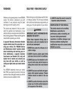
CUSTOMIZE PARAMETERS
HINT:
The following can be customized.
NOTICE:
• When the customer requests a change in a function,
first make sure that the function can be customized.
• Be sure to make a note of the current settings before
customizing.
• When troubleshooting a function, first make sure that
the function is set to the default setting.
1. THEFT DETERRENT SYSTEM
Theft Deterrent System
Display (Item)
Default
Contents
Setting
PASSIVE MODE
(Passive Arming Mode)
OFF
In passive arming mode, theft
deterrent system switched from
arming preparation state to armed
state 30 seconds after both of
following operations performed.
• Key removed from ignition
key cylinder
• All doors closed (not locked)
In passive arming mode, if
following operations are not
performed within 14 seconds of
door being opened while in armed
state, theft deterrent system
determines that condition as theft
and switches to alarm arming
sounding state.
• Battery reconnected
• Key inserted into ignition key
cylinder and ignition switch
turned from OFF to ON
• Any door unlocked using key
ON/OFF
WARNING (HORN)
(Warning horn)
ON
Allows vehicle horn and security
horn to be used as warning
devices
ON/OFF
ENTRY DELAY (Entry delay time)
14 seconds
Changes entry delay time (time
before warning starts) for passive
arming mode
0 /14 /30 (seconds)
2.
HINT:
Sensitivity adjustments are difficult to confirm. Check by
driving the customer's vehicle.
LIGHTING SYSTEM
Illuminated Entry
Display (Item)
Default
Contents
Setting
LIGHTING TIME
(Lighting Time)
15 seconds
Changes illumination duration
after door closure.
(It will quickly fade out in case of
turning the ignition switch ON.)
7.5 seconds / 15 seconds /
30seconds
I/L ON /ACC OFF
(Room light illuminates when
ignition switch turned off)
ON
Illuminates light when ignition
switch turned on (ACC).
(Room light illuminated when
interior light switch in DOOR
position)
ON / OFF
I/L ON / UNLOCK
(Room light illuminates when
door key unlocked.)
ON
Function to light up the room light,
when unlocking with the door key
cylinder.
(Room light illuminated when
interior light switch in DOOR
position)
ON/OFF
IN
IN–26
INTRODUCTION – HOW TO TROUBLESHOOT ECU CONTROLLED SYSTEMS
HOW TO TROUBLESHOOT ECU
CONTROLLED SYSTEMS
GENERAL INFORMATION
IN
A large number of ECU controlled systems are used in the
YARIS. In general, ECU controlled systems are considered to
be very intricate, requiring a high level of technical knowledge
to troubleshoot. However, most problem checking procedures
only involve inspecting the ECU controlled system's circuits
one by one. An adequate understanding of the system and a
basic knowledge of electricity is enough to perform effective
troubleshooting, accurate diagnoses and necessary repairs.
FOR USING INTELLIGENT TESTER
• Before using the intelligent tester, read the tester
operator's manual thoroughly.
• If the tester cannot communicate with the ECU controlled
systems when the tester is connected to the DLC3 with the
engine switch on (IG) and the tester turned ON, there is a
problem on the vehicle side or tester side.
(a)If communication is normal when the tester is
connected to another vehicle, inspect the diagnosis
data link line (Bus (+) line) or ECU power circuit of the
vehicle.
(b)If communication is still not possible when the tester is
connected to another vehicle, the problem is probably
in the tester itself. Perform the Self Test procedures
outlined in the tester operator's manual.
INTRODUCTION – HOW TO TROUBLESHOOT ECU CONTROLLED SYSTEMS
IN–35
ELECTRONIC CIRCUIT INSPECTION
PROCEDURE
1.
INCORRECT
INCORRECT
CORRECT
D032092E01
Looseness of
Crimping
Core Wire
Terminal
Deformation
Pull Lightly
D025087E03
BASIC INSPECTION
(a) WHEN MEASURING RESISTANCE OF
ELECTRONIC PARTS
(1) Unless otherwise stated, all resistance
measurements should be made at an ambient
temperature of 20°C (68°F). Resistance
measurements may be inaccurate if measured
at high temperatures, i.e. immediately after the
vehicle has been running. Measurements should
be made after the engine has cooled down.
(b) HANDLING CONNECTORS
(1) When disconnecting a connector, first squeeze
the mating halves tightly together to release the
lock, and then press the lock claw and separate
the connector.
(2) When disconnecting a connector, do not pull on
the harnesses. Grasp the connector directly and
separate it.
(3) Before connecting a connector, check that there
are no deformed, damaged, loose or missing
terminals.
(4) When connecting a connector, press firmly until
it locks with a "click" sound.
(5) If checking a connector with a TOYOTA
electrical tester, check the connector from the
backside (harness side) using a mini test lead.
NOTICE:
• As a waterproof connector cannot be
checked from the backside, check it by
connecting a sub-harness.
• Do not damage the terminals by moving
the inserted tester needle.
(c) CHECKING CONNECTORS
(1) Checking when a connector is disconnected:
Squeeze the connector together to confirm that
they are fully connected and locked.
(2) Checking when a connector is disconnected:
Check by pulling the wire harness lightly from
the backside of the connector. Look for
unlatched terminals, missing terminals, loose
crimps or broken conductor wires. Check
visually for corrosion, metallic or foreign matter
and water, and bent, rusted, overheated,
contaminated, or deformed terminals.
NOTICE:
When testing a gold-plated female terminal,
always use a gold-plated male terminal.
IN
IN–40
INTRODUCTION – TERMS
TERMS
ABBREVIATIONS USED IN MANUAL
Abbreviations
IN
ABS
Meaning
Anti-Lock Brake System
A/C
Air Conditioner
AC
Alternating Current
ACC
Accessory
ACIS
Acoustic Control Induction System
ACM
Active Control Engine Mount
ACSD
Automatic Cold Start Device
A.D.D
Automatic Disconnecting Differential
A/F
Air-Fuel Ratio
AHC
Active Height Control Suspension
ALR
Automatic Locking Retractor
ALT
Alternator
AMP
Amplifier
ANT
Antenna
APPROX.
Approximately
ASSY
Assembly
A/T, ATM
Automatic Transmission (Transaxle)
ATF
Automatic Transmission Fluid
AUTO
Automatic
AUX
Auxiliary
AVG
Average
AVS
Adaptive Variable Suspension
B+
Battery Voltage
BA
Brake Assist
BACS
Boost Altitude Compensation System
BAT
Battery
BDC
Bottom Dead Center
B/L
Bi-Level
B/S
Bore-Stroke Ratio
BTDC
Before Top Dead Center
BVSV
Bimetallic Vacuum Switching Valve
CAN
Controller Area Network
CB
Circuit Breaker
CCo
Catalytic Converter For Oxidation
CCV
Canister Closed Valve
CD
Compact Disc
CF
Cornering Force
CG
Center Of Gravity
CH
Channel
CKD
Complete Knock Down
COMB.
Combination
CPE
Coupe
CPS
Combustion Pressure Sensor
CPU
Central Processing Unit
CRS
Child Restraint System
CTR
Center
IN–46
INTRODUCTION – TERMS
GLOSSARY OF SAE AND TOYOTA
TERMS
This glossary lists all SAE-J1930 terms and abbreviations
used in this manual in compliance with SAE
recommendations, as well as their TOYOTA equivalents.
IN
SAE
ABBREVIATIONS
A/C
TOYOTA TERMS
( )-ABBREVIATIONS
SAE TERMS
Air Conditioning
Air Conditioner
ACL
Air Cleaner
Air Cleaner, A/CL
AIR
Secondary Air Injection
Air Injection (AI)
AP
Accelerator Pedal
-
B+
Battery Positive Voltage
+B, Battery Voltage
BARO
Barometric Pressure
HAC
CAC
Charge Air Cooler
Intercooler
CARB
Carburetor
Carburetor
CFI
Continuous Fuel Injection
-
CKP
Crankshaft Position
Crank Angle
CL
Closed Loop
Closed Loop
CMP
Camshaft Position
Cam Angle
CPP
Clutch Pedal Position
-
CTOX
Continuous Trap Oxidizer
-
CTP
Closed Throttle Position
LL ON, Idle ON
DFI
Direct Fuel Injection
Direct Injection (DI./INJ)
DI
Distributor Ignition
-
DLC3
Data Link Connector 3
OBD II Diagnostic Connector
DTC
Diagnostic Trouble Code
Diagnostic Trouble Code
DTM
Diagnostic Test Mode
-
ECL
Engine Coolant Level
-
ECM
Engine Control Module
Engine ECU (Electronic Control Unit)
ECT
Engine Coolant Temperature
Coolant Temperature, Water Temperature (THW)
EEPROM
Electrically Erasable Programmable Read Only Memory
Electrically Erasable Programmable Read Only
Memory (EEPROM), Erasable Programmable Read
Only Memory (EPROM)
EFE
Early Fuel Evaporation
Cold Mixture Heater (CMH), Heat Control Valve (HCV)
EGR
Exhaust Gas Recirculation
Exhaust Gas Recirculation (EGR)
EI
Electronic Ignition
Distributorless Ignition (DLI)
EM
Engine Modification
Engine Modification (EM)
EPROM
Erasable Programmable Read Only Memory
Programmable Read Only Memory (PROM)
EVAP
Evaporative Emission
Evaporative Emission Control (EVAP)
FC
Fan Control
-
FEEPROM
Flash Electrically Erasable Programmable Read Only
Memory
-
FEPROM
Flash Erasable Programmable Read Only Memory
-
FF
Flexible Fuel
-
FP
Fuel Pump
Fuel Pump
GEN
Generator
Alternator
GND
Ground
Ground (GND)
HO2S
Heated Oxygen Sensor
Heated Oxygen Sensor (HO2s)
IAC
Idle Air Control
Idle Speed Control (ISC)
IAT
Intake Air Temperature
Intake or Inlet Air Temperature
ICM
Ignition Control Module
-
PREPARATION – 1NZ-FE ENGINE CONTROL SYSTEM
PP–1
1NZ-FE ENGINE CONTROL SYSTEM
PREPARATION
SST
09817-33190
Sensor Socket Wrench
PP
PREPARATION – 1NZ-FE ENGINE CONTROL SYSTEM
PP–3
EQUIPMENT
Torque wrench
Ohmmeter
Heater
Thermometer
PP
PP–2
PREPARATION – 1NZ-FE ENGINE MECHANICAL
1NZ-FE ENGINE MECHANICAL
PREPARATION
SST
PP
09011-38121
12 mm Socket Wrench for 12
Pointed Head
09023-38400
Union Nut Wrench 14mm
09032-00100
Oil Pan Seal Cutter
09201-10000
Valve Guide Bushing Remover &
Replacer Set
(09201-01050)
Valve Guide Bushing Remover &
Replacer 5
09201-41020
Valve Stem Oil Seal Replacer
09202-70020
Valve Spring Compressor
(09202-00010)
Attachment
09205-16010
Cylinder Head Bolt Wrench
09213-14010
Crankshaft Pulley Holding Tool
(91651-60865)
Bolt
PREPARATION – 1NZ-FE ENGINE MECHANICAL
PP–5
RECOMMENDED TOOLS
09011-12301
Socket Wrench 30 mm
09040-00011
Hexagon Wrench Set
PP
(09043-20080)
Socket Hexagon Wrench 8
(09043-20100)
Socket Hexagon Wrench 10
09216-00021
Belt Tension Gauge
PREPARATION – 1NZ-FE ENGINE MECHANICAL
PP–7
SSM
08826-00080
Seal Packing Black or equivalent
(FIPG)
08826-00100
Seal Packing 1282B,
THREE BOND 1282B or equivalent
(FIPG)
08833-00070
Adhesive 1324,
THREE BOND 1324 or equivalent
PP
PREPARATION – 1NZ-FE FUEL
PP–7
1NZ-FE FUEL
PREPARATION
SST
09268-41047
Injection Measuring Tool Set
(09268-41500)
Fuel Tube Connector
(90467-13001)
Clip
(95336-08070)
Hose
09268-41048
Injection Measuring Tool Set
(09268-41110)
Adaptor
(09268-41310)
Clamp
(09268-41500)
Fuel Tube Connector
(90467-13001)
Clip
(95336-08070)
Hose
09268-45014
EFI Fuel Pressure Gauge
PP
PREPARATION – 1NZ-FE FUEL
PP–9
RECOMMENDED TOOLS
09082-00040
(09083-00150)
TOYOTA Electrical Tester
Test Lead Set
PP
PREPARATION – 1NZ-FE FUEL
PP–11
SSM
08826-00080
Seal Packing Black or equivalent
(FIPG)
PP
PP–10
PREPARATION – 1NZ-FE EMISSION CONTROL
1NZ-FE EMISSION CONTROL
PREPARATION
SST
09224-00010
PP
O2 Sensor Wrench
PP–12
EQUIPMENT
Ohmmeter
Torque wrench
Service wire harness
PP
PREPARATION – 1NZ-FE EMISSION CONTROL
PREPARATION – 1NZ-FE EXHAUST
PP–11
1NZ-FE EXHAUST
PREPARATION
EQUIPMENT
Torque wrench
Vernier calipers
Wooden block
PP
PP–12
PREPARATION – 1NZ-FE COOLING
1NZ-FE COOLING
PREPARATION
SST
09960-10010
PP
Variable Pin Wrench Set
(09962-01000)
Variable Pin Wrench Arm Assembly
(09963-00700)
Pin 7
PP–14
PREPARATION – 1NZ-FE COOLING
COOLANT
Item
Capacity
M/T 4.8 liters (5.1 USqts, 4.5 lmp. qts)
4.7 liters (5.0 USqts, 4.4 lmp. qts)
Engine Coolant
PP
A/T
Classification
Use only Toyota Super Long Life Coolant or similar high
quality ethylene glycol based non-silicate, non-amine,
non-nitrite, and non-borate engine coolant with long-life
hybrid organic acid technology (coolant with long-life
hybrid organic acid technology consists of a
combination of low phosphates and organic acids).
PREPARATION – 1NZ-FE LUBRICATION
PP–13
1NZ-FE LUBRICATION
PREPARATION
SST
09213-14010
(91651-60865)
Crankshaft Pulley Holding Tool
Bolt
09228-06501
Oil Filter Wrench
09330-00021
Companion Flange Holding Tool
09950-60010
Replacer Set
(09951-00250)
Replacer 25
(09951-00410)
Replacer 41
(09952-06010)
Adapter
09950-70010
Handle Set
(09951-07100)
Handle 100
PP
PP–15
PREPARATION – 1NZ-FE LUBRICATION
LUBRICANT
Item
Capacity
With oil filter change
3.7 liters (3.9 US qts, 3.4 lmp. qts)
Without oil filter change
3.4 liters (3.6 US qts, 3.1 lmp. qts)
Dry fill
4.1 liters (4.3 US qts, 3.8 lmp. qts)
PP
PREPARATION – 1NZ-FE IGNITION
PP–15
1NZ-FE IGNITION
PREPARATION
RECOMMENDED TOOLS
09082-00040
(09083-00150)
TOYOTA Electrical Tester
Test Lead Set
PP