BANG TINH DAM T CẦU ĐƯỜNG TIẾNG ANH
Bạn đang xem bản rút gọn của tài liệu. Xem và tải ngay bản đầy đủ của tài liệu tại đây (531.09 KB, 36 trang )
05. Calculation Super T Girder L=38.2m_Skew 20.xls【I.General】
SHEET NO. : 1 / 1
1. GENERAL
1.1. Design standard
Specification for Bridge Design: 22TCN-272-05
1.2. Material strength and stress limits
1.2.1 Prestressing Steel:
Type of low relaxation strand complies with : ASTM A416, Grade 270
Diameter of tendon
=
15.2 mm
Area of tendon
=
140 mm2
Tensile Strength fpu
=
1860 MPa
Yield Strength fpy
=
1674 MPa
Modulus of elasticity of strand Ep
=
197000 Modulus Ratio np = Ep/Ec
=
6.00
1395 MPa <=> Jacking Force
=
195.30 kN
Stress in the prestressing steel at jacking =
1.2.2 Reinforcing Steel:
Reinf . Standart ASTM or TCVN 1651-2008
Yield strength fs
=
400 MPa
Modulus of elasticity Es
=
200000 MPa
1.2.3 Concrete:
1.2.3.1 Main Girder:
Specified compressive strength at 28 days f'c
=
50 MPa
Compressive strength at time of initial prestress f'ci
=
42.50 MPa
Modulus of elasticity Ec
=
38007 MPa
(5.4.2.4-1)
Modulus of elastic of concrete at release time Eci
=
35041 MPa
(5.4.2.4-1)
Tensile strength of concrete at 28 days fr
=
4.45 MPa
Specified compressive strength at 28 days f'c
=
35 MPa
Modulus of elasticity Ed
=
1.2.3.2 Deck Slab:
1.3. Design loads and load combination
1.3.1 Dead Loads:
+ Unit weight of Concrete
= 2500 Kg/m3
+ Unit weight of reinforcement Concrete
= 7850 Kg/m3
+ Unit weight of asphant concrete
= 2300 Kg/m3
1.3.2 Live Loads:
+ Live Loads HL93
Checked by LEE, Jong Dae
Approved by CHO, Wan Hyoung
31799 Mpa => nd = Ed/Ec
= 0.84
05. Calculation Super T Girder L=38.2m_Skew 20.xls【II.Section】
SHEET NO. : 1 / 4
2. GEOMETRIC PROPERTIES
ELEVATION
A
B
SECTION A-A
C
B
b1
b2
h8
CL OF BEARING
h2
h5
9
3
1
h1
hd
hd
b3
10
11
b9
b9
7
5
h1-hd
5
b1
L2
bd
L3
A
B
b4
C
SECTION B-B
SECTION C-C
B
B
b3
1
3
h9
9
11
10
b9
b11
5
4
h3
h1
H
5
b3
b12
h5
10
b9
h1
3
11
b9
b2
2
h2
h5
h2
9
1
H
b1
h8
b2
h8
b1
b3
b4
b7
7
b7
b8 b8
5
h6
L1
h4
h7
6
b1
bd
b4
b3
b1
b4
b10
8
b4
7
b6
b5
b4
b3
b5
2.1. Dimension profiles
Distance from bearing to end of girder
Distance from bearing to girder notch
Length of full section (not inlcude notch)
Items
Distance to bearing
Section in/out of length of link slab
Height of girder
Height of composite section
Height of other components
Slab thickness
Thickness of precast concrete plate
Effective width of concrete slab
Width of other components
Checked by LEE, Jong Dae
Approved by CHO, Wan Hyoung
Notation
h1; hd
H
h2
h3
h4
h5
h6
h7
h8
h9
B
b1
b2
b3
b4
b5
b6
b7
L1
L2
L3
= 550 mm
= 450 mm
= 1200 mm
Sec. 1
Sec. 2 Sec. 3 Sec. 4 Sec. 5 Sec. 6
18550
14750
10950
6450
3850
1650
no
no
no
no
no
yes
1750.0
1750
1750
1750
1750
1750
1945.0
1945
1945
1945
1945
1750
75.0
75
75
75
75
75
1425.0
1425
1425
1425
1425
250.0
250
250
250
250
75.0
75
75
75
75
75
350.0
350
350
350
350
50.0
50
50
50
50
195.0
195
195
195
195
195
35.0
35
35
35
35
2350.0
2350
2350
2350
2350
2350
650.0
650
650
650
650
650
1050.0
1050
1050
1050
1050
1050
650.0
650
650
650
650
650
175.0
175
175
175
175
175.0
135.0
135
135
135
135
430.0
430
430
430
430
82.5
82.5
82.5
82.5
82.5
Sec. 7
450
yes
800
800
75
75
195
2350
650
1050
650
65
05. Calculation Super T Girder L=38.2m_Skew 20.xls【II.Section】
SHEET NO. : 2 / 4
b8
b9
b10
b11
b12
bd
Width of girder bottom
215.0
100.0
25.7
7.5
810.0
700.0
215
100
25.7
7.5
810
700
215
100
25.7
7.5
810
700
215
100
25.7
7.5
810
700
215
100
25.7
7.5
810
700
100
100
700
920
Sec. 1
Sec. 2
Sec. 3
Sec. 4
Sec. 5
Sec. 6
650
650
650
650
650
650
75
75
75
75
75
75
48750
48750
48750
48750
48750
48750
7.5
7.5
7.5
7.5
7.5
75
75
75
75
75
562.5
562.5
562.5
562.5
562.5
100
100
100
100
100
100
75.0
75
75
75
75
75
7500
7500
7500
7500
7500
7500
135
135
135
135
135
1750
1750
1750
1750
1750
472500 472500 472500 472500 472500
82.5
82.5
82.5
82.5
82.5
175.0
350
350
350
350
350
1675
28875
28875
28875
28875
28875 293125
215
215
215
215
215
50
50
50
50
50
10750
10750
10750
10750
10750
430
430
430
430
430
700
250
250
250
250
250
1675
107500 107500 107500 107500 107500 1172500
25.7
25.7
25.7
25.7
25.7
250
250
250
250
250
6425
6425
6425
6425
6425
650
650
650
650
650
650
75
75
75
75
75
75
48750
48750
48750
48750
48750
48750
1050
75
78750
Sec. 7
650
75
48750
2.2. Section properties in each stage
2.2.1 Stage I&II: Non-composite section
2.2.1.1 Section area:
Element Shape QuantityNotation
K1
chữ nhật
1
b
rectangle
h
A1
K2
tam giác
2
b
triangle
h
A2
K3
tam giác
2
b
triangle
h
A3
K4
chữ nhật
2
b
rectangle
h
A4
K5
tam giác
2
b
triangle
h
A5
K6
tam giác
2
b
triangle
h
A6
K7
chữ nhật
1
b
rectangle
h
A7
K8
tam giác
2
b
triangle
h
A8
K10
chữ nhật
1
b
rectangle
h
A10
K11
chữ nhật
1
b
rectangle
h
A11
K12
A12
Tendon
Unit
(mm)
(mm)
(mm2)
(mm)
(mm)
(mm2)
(mm)
(mm)
(mm2)
(mm)
(mm)
(mm2)
(mm)
(mm)
(mm2)
(mm)
(mm)
(mm2)
(mm)
(mm)
(mm2)
(mm)
(mm)
(mm2)
(mm)
(mm)
(mm2)
(mm)
(mm)
(mm2)
(mm2)
A I&II
Total section area
30800
30800
30800
28000
762413
762413
762413
759613
23100
18900
100
75
7500
65
725
47125
920
725
667000
650
75
48750
1050
75
78750
-
754713 1668275
897875
Sec. 1
Sec. 2
Sec. 3
Sec. 4
Sec. 5
Sec. 6
1713
1713
1713
1713
1713
1713
Sec. 7
763
2.2.1.2 Static moment of area
Items
Distance from centroid of
Notation
z1
Unit
(mm)
component to bottom fiber
z2
(mm)
1700
1700
1700
1700
1700
of girder
z3
(mm)
1650
1650
1650
1650
1650
z4
(mm)
875
875
875
875
875
z5
(mm)
367
367
367
367
367
z6
(mm)
267
267
267
267
267
Checked by LEE, Jong Dae
Approved by CHO, Wan Hyoung
1650
700
1117
483
05. Calculation Super T Girder L=38.2m_Skew 20.xls【II.Section】
SHEET NO. : 3 / 4
z7
(mm)
z8
(mm)
z10
(mm)
z11
(mm)
Tendon
Static moment of inertia of
component about bottom
z12
(mm)
s1
(mm3)
fiber of girder
s2
s3
s4
s5
s6
125
125
838
363
1713
763
1713
763
166.6667 166.667 166.667 166.667 166.667
1713
191
1713
191
1713
191
1713
195
1713
236
236
-
83484375 8.3E+07 8.3E+07 8.3E+07 8.3E+07 8.3E+07 3.7E+07
956250
956250
956250
956250
956250
-
-
12375000 1.2E+07 1.2E+07 1.2E+07 1.2E+07 1.2E+07 5250000
4.13E+08 4.1E+08 4.1E+08 4.1E+08 4.1E+08
3
10587500 1.1E+07 1.1E+07 1.1E+07 1.1E+07 3.3E+08 2.3E+07
(mm )
(mm )
3
(mm )
3
(mm3)
SI&II
125
3
(mm )
(mm )
s12
125
3
s8
s11
Tendon
(mm )
s7
s10
Total for stage I&II
3
125
3
(mm )
2866667 2866667 2866667 2866667 2866667
1070833 1070833 1070833 1070833 1070833
3
(mm )
-
-
-
83484375 8.3E+07 8.3E+07 8.3E+07 8.3E+07 8.3E+07 3.7E+07
1798125
(mm )
(mm )
-
-
13437500 1.3E+07 1.3E+07 1.3E+07 1.3E+07 9.8E+08 2.4E+08
3
3
-
5897500 5897500 5897500 5456500 5456500 4464409
800625
-
6.28E+08 6.3E+08 6.3E+08 6.3E+08 6.3E+08 1.5E+09 3.4E+08
2.2.1.3. Centroid
Distance from neutral axis
to top fiber of girder
Distance from neutral axis
to bottom fiber of girder
yt1 (mm)
-927
-927
-927
-924
-919
-854
-416
yd1 (mm)
823
823
823
826
831
896
384
Distance from center
e1
(mm)
-889
-889
-889
-887
-882
-816
-378
of component to neutral axis
e2
(mm)
-877
-877
-877
-874
-869
896
384
e3
(mm)
-827
-827
-827
-824
-819
-754
-316
e4
(mm)
-52
-52
-52
-49
-44
896
384
e5
(mm)
457
457
457
459
464
-221
-99
e6
(mm)
557
557
557
559
564
896
384
e7
(mm)
698
698
698
701
706
59
22
e8
(mm)
657
657
657
659
664
896
384
e10
(mm)
-889
-889
-889
-887
-882
-816
-378
e11
(mm)
-816
-378
e12
(mm)
660
384
22851563 2.3E+07 2.3E+07 2.3E+07 2.3E+07 2.3E+07
2E+07
Tendon
2.2.1.4. Moment of inertia
a. About centroid of components
I1
(mm4)
I2
I3
I4
I5
I6
4
(mm )
175781
631
175781
595
175781
1.97E+08
(mm )
-
2E+08
2E+08
2E+08
-
2E+08 4.6E+10
4
1493056 1493056 1493056 1493056 1493056
4
5.6E+08 5.6E+08 5.6E+08 5.6E+08 5.6E+08 2.7E+11
(mm )
-
2343750 2343750 2343750 2343750 2343750 2343750 2343750
1.21E+11 1.2E+11 1.2E+11 1.2E+11 1.2E+11
(mm4)
Checked by LEE, Jong Dae
Approved by CHO, Wan Hyoung
175781
632
4
(mm )
(mm )
I12
175781.3
632
4
I8
I11
15.2 mm
Sum (a)
(mm )
I7
I10
D=
4
632
22309028 2.2E+07 2.2E+07 2.2E+07 2.2E+07
-
1E+09
3E+10
-
4
22851563 2.3E+07 2.3E+07 2.3E+07 2.3E+07 2.3E+07
2E+07
4
4E+07
4E+07
(mm )
(mm )
4
(mm )
691748.4 691748 691748 628862 518811 518811
0E+00
1.21E+11 1.2E+11 1.2E+11 1.2E+11 1.2E+11 3.2E+11 3.1E+10
05. Calculation Super T Girder L=38.2m_Skew 20.xls【II.Section】
SHEET NO. : 4 / 4
b. Moment of inertia of components about centroid of section
I1
(mm4) 3.86E+10 3.9E+10 3.9E+10 3.8E+10 3.8E+10 3.2E+10 7E+09
I2
(mm4) 4.32E+08 4.3E+08 4.3E+08 4.3E+08 4.2E+08
4
I3
(mm ) 5.13E+09 5.1E+09 5.1E+09 5.1E+09 5E+09 4.3E+09 7.5E+08
I4
(mm4) 1.27E+09 1.3E+09 1.3E+09 1.2E+09 9.2E+08
I5
I6
6.02E+09
6E+09
6E+09 6.1E+09 6.2E+09 1.4E+10 4.6E+08
4
3.33E+09 3.3E+09 3.3E+09 3.4E+09 3.4E+09
4
(mm )
I7
(mm )
5.24E+10 5.2E+10 5.2E+10 5.3E+10 5.4E+10
I8
(mm4)
2.77E+09 2.8E+09 2.8E+09 2.8E+09 2.8E+09
I10
I11
Sum (b)
Moment of inertia stage I&II
(mm4)
4
(mm )
-
-
4E+09 3.1E+08
-
3.86E+10 3.9E+10 3.9E+10 3.8E+10 3.8E+10 3.2E+10
7E+09
4
5.2E+10 1.1E+10
4
1.23E+10 1.2E+10 1.2E+10 1.1E+10 8.2E+09 8.2E+09
1.61E+11 1.6E+11 1.6E+11 1.6E+11 1.6E+11 1.5E+11 2.7E+10
2.82E+11 2.8E+11 2.8E+11 2.8E+11 2.8E+11 4.7E+11 5.7E+10
(mm )
I12
(mm )
II&II
(mm4)
2.2.2. Stage III: Composite section
K9
chữ nhật
rectangle
1
b
h
A9
(mm2)
ΣA III
(mm2)
Distance from K9 to bottom
fiber of girder
z9
(mm)
Static moment of K9 about
bottom fiber of girder
s9
Total static moment of area
SIII
Total section area
(mm)
(mm)
2350
195
458250
2350
195
458250
2350
195
458250
2350
195
458250
2350
195
458250
-
1220663 1220663 1220663 1217863 1212963 1668275
1847.5
1847.5
1847.5
1847.5
897875
1847.5
1750
800
(mm3)
8.47E+08 8.5E+08 8.5E+08 8.5E+08 8.5E+08
-
-
(mm3)
1.47E+09 1.5E+09 1.5E+09 1.5E+09 1.5E+09 1.5E+09 3.4E+08
Distance from neutral axis
to top fiber of girder
yt2 (mm)
-542
-542
-542
-540
-535
-854
-416
Distance from neutral axis
to bottom fiber of girder
yd2 (mm)
1208
1208
1208
1210
1215
896
384
Distance from neutral axis
to top fiber of slab
yb2 (mm)
-737
-737
-737
-735
-730
-854
-416
Distance from neutral axis
to center of tendons
ec2 (mm)
1016
1016
1016
1015
979
660
384
Moment of inertia stage I&II
Distance from neutral axis
of stage I to stage II
Moment of inertia about
centroid of section at stage
II
Moment of inertia of K9
Distance from center of K9
to neutral axis of composite
section
Moment of inertia about
centroid of composite
section
Moment of inertia of
composite section
II&II
(mm4)
e (mm)
(mm4)
I9
4
(mm )
(mm)
IIII
Checked by LEE, Jong Dae
Approved by CHO, Wan Hyoung
2.82E+11 2.8E+11 2.8E+11 2.8E+11 2.8E+11 4.7E+11 5.7E+10
-385
-385
-385
-385
-384
-
-
-
-
1.13E+11 1.1E+11 1.1E+11 1.1E+11 1.1E+11
1.45E+09 1.5E+09 1.5E+09 1.5E+09 1.5E+09
-640
-640
-640
-637
-632
-756
-318
(mm4)
1.88E+11 1.9E+11 1.9E+11 1.9E+11 1.8E+11
-
-
(mm4)
5.84E+11 5.8E+11 5.8E+11 5.8E+11 5.7E+11 4.7E+11 5.7E+10
05. Calculation Super T Girder L=38.2m_Skew 20.xls【III.Tendon】
SHEET NO. : 1 / 4
3. TENDON ARRANGEMENT
3.1. Input date
Using straight tendons with diameter
2
140.0 mm
15.2 mm <=> A_ten
To reduce tensile stress at bearing locations, unbonded tendons are created by using PE tube
Effective length of tendons
Type of tendons
Effective length (m)
Remark
1
36.20
Full length tendons
2
34.20
Tendons with 1.0m unbonded
3
30.20
Tendons with 3.0m unbonded
4
26.20
Tendons with 5.0m unbonded
5
22.20
Tendons with 7.0m unbonded
Tendon
h(mm)
Number of strands
bottom
1
2
3
4
Tendon
h(mm) Number of strands
5
top
1
Row E
Row A
75
7
2
2
Row B
130
8
2
1
2
Row C
185
6
2
2
2
Row D
240
4
1690
2
2
2
h(mm): distance from center of tendons to bottom fiber of girder
510
60
ROW E
HÀNG E
ROW D - HÀNG D
ROW C - HÀNG C
ROW B - HÀNG B
ROW A - HÀNG A
55 55
75 55
250
1750
510
60
SECTION
1
3
2
50
5
4
7
6
9 11 13
8 10 12
12x50=600
700
50
TABLE OF NUMBER, LOCATION AND DEBONDING LENGTHS OF STRANDS
STRAND (Ndeg)
1
ROW E
1000
+
+
+
ROW D
ROW C
ROW B
ROW A
2
3
+
3000
+
+
5000
+
3000
+
4
5000
+
3000
5
+
7000
+
6
7000
+
5000
7
5000
+
8
7000
+
5000
TOTAL NUMBER OF STRANDS : 44 (A - E)
Checked by LEE, Jong Dae
Approved by CHO, Wan Hyoung
9
+
7000
+
10
11
12
5000
+
3000
5000
+
3000
+
+
3000
+
+
13
1000
+
+
+
05. Calculation Super T Girder L=38.2m_Skew 20.xls【III.Tendon】
SHEET NO. : 2 / 4
3.2. Sum of tendons at sections
Section
Type of tendons
Aps (mm2)
Area of tendons
1
2
3
4
5
1
2
3
4
5
1
√
√
√
√
√
3500
280
840
980
560
2
√
√
√
√
√
3500
280
840
980
560
3
√
√
√
√
√
3500
280
840
980
560
4
√
√
√
√
X
3500
280
840
980
0
5
√
√
√
X
X
3500
280
840
0
0
6
√
√
X
X
X
3500
280
0
0
0
7
X
X
X
X
X
0
0
0
0
0
Section
Distance from center of tendons to bottom fiber of girder
Distance from center of ΣA
all tendons
ps(mm
2
)
1
2
3
4
5
to bottom fiber of girder
n
1
145
1690
130
161
158
191 mm
6160
44
2
145
1690
130
161
158
191 mm
6160
44
3
145
1690
130
161
158
191 mm
6160
44
4
145
1690
130
161
0
195 mm
5600
40
5
145
1690
130
0
0
236 mm
4620
33
6
145
1690
0
0
0
260 mm
3780
27
7
0
0
0
0
0
0 mm
0
0
3.3. Force transfering length & developing length of tendons
= 60dp =
Force transfering length (mm)
912 (5.11.4.1-272-05)
Developing length of normal tendon (mm)
ld = [0.15fps-0.097fpe]dp =
2535 (5.11.4.2-272-05)
Developing length of covered tendon (mm)
ld = 2[0.15fps-0.097fpe]dp =
5071 (5.11.4.3-272-05)
Group 1:
25 tendons with bond length taken from girder edge
0 mm
Group 2:
2 tendons with bond length taken from girder edge
1000 mm
Group 3:
6 tendons with bond length taken from girder edge
3000 mm
Group 4:
7 tendons with bond length taken from girder edge
5000 mm
Group 5:
4 tendons with bond length taken from girder edge
7000 mm
Prestress of tendons at tension stage - prestress loss due to shrinkage =
1304 MPa
Prestress in tendons after all loss =
1104 MPa
Prestress of tendons for bending resistant =
1826 MPa
Checked by LEE, Jong Dae
Approved by CHO, Wan Hyoung
05. Calculation Super T Girder L=38.2m_Skew 20.xls【III.Tendon】
SHEET NO. : 3 / 4
3.4. Internal forces due to prestressed tendons at sections
PRESTRESSING FORCE FOR TENDONS
Group number
Distance from section to girder notch (mm)
14300
10500
Compression forces at tension stage
Group 1:
4563.31
Group 2:
365.06
Group 3:
1095.19
Group 4:
1277.73
Group 5:
730.13
18100
4563.31
365.06
1095.19
1277.73
730.13
4563.31 4563.31 4563.31 4563.31
365.06
365.06
365.06
80.06
1095.19 1095.19
480.35
0.00
1277.73 1277.73
0.00
0.00
730.13
0.00
0.00
0.00
0.00
0.00
0.00
0.00
0.00
Summary (kN)
8031.42
8031.42 7301.29 5408.72 4643.37
0.00
3865.63 3865.63 3865.63 3865.63
0.00
8031.42
6000
3400
1200
0
Compression forces after all prestress loss
Group 1:
3865.63
3865.63
Group 2:
309.25
309.25
309.25
309.25
309.25
67.82
0.00
Group 3:
927.75
927.75
927.75
927.75
406.91
0.00
0.00
Group 4:
1082.38
1082.38
1082.38 1082.38
0.00
0.00
0.00
Group 5:
618.50
618.50
0.00
0.00
0.00
6803.51
6803.51
6803.51 6185.01 4581.79 3933.45
0.00
6391.66 6391.66 6344.55 4152.58
0.00
Summary (kN)
618.50
0.00
Compression forces to determine resistant
Group 1:
6391.66
6391.66
Group 2:
511.33
511.33
472.17
368.55
67.82
0.00
Group 3:
1534.00
1534.00
1534.00 1177.40
406.91
0.00
0.00
Group 4:
1789.66
1789.66
1722.35 1094.65
0.00
0.00
0.00
Group 5:
1022.67
1022.67
0.00
0.00
0.00
11249.32 11249.32 10984.12 9135.88 7120.01 4220.40
0.00
Summary (kN)
511.33
824.78
0.00
Tendon Group 1 to bottom
fiber of girder (mm)
145.40
145.40
Tendon Group 2 to bottom
fiber of girder (mm)
1690.00
1690.00
Tendon Group 3 to bottom
fiber of girder (mm)
130.00
130.00
130.00
130.00
130.00
0.00
0.00
Tendon Group 4 to bottom
fiber of girder (mm)
161.43
161.43
161.43
161.43
0.00
0.00
0.00
Tendon Group 5 to bottom
fiber of girder (mm)
157.50
157.50
157.50
0.00
0.00
0.00
0.00
677.77
680.23
685.59
750.67
0.00
-866.83
-864.37
-859.01
-793.93
0.00
693.17
695.63
700.99
896.07
0.00
661.74
664.20
830.99
896.07
0.00
665.67
825.63
830.99
896.07
0.00
-4867.15 -4399.04 -3151.67 -3362.00
0.00
-4123.02 -3726.48 -2669.82 -2847.99
0.00
Prestressing moment at tension stage (kN-m)
Tendon Group 1 to neutral
axis (mm)
677.77
677.77
Tendon Group 2 to neutral
axis (mm)
-866.83
-866.83
Tendon Group 3 to neutral
axis (mm)
693.17
693.17
Tendon Group 4 to neutral
axis (mm)
661.74
661.74
Tendon Group 5 to neutral
axis(mm)
665.67
665.67
Sum of moment (kN-m)
-4867.15 -4867.15
145.40
145.40
145.40
145.40
0.00
1690.00 1690.00 1690.00 1690.00
0.00
Prestressing moment after all stress losses (kN-m)
Sum of moment (kN-m)
-4123.02 -4123.02
Checked by LEE, Jong Dae
Approved by CHO, Wan Hyoung
Lực nén - Compression force (kN)
05. Calculation Super T Girder L=38.2m_Skew 20.xls【III.Tendon】
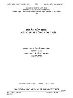
SHEET NO. : 4 / 4
Lực nén trước và sau các mất mát ứng suất
Compression forces before and after all prestress loss
9000.00
8000.00
7000.00
6000.00
5000.00
4000.00
3000.00
2000.00
1000.00
0.00
0
1000 2000 3000 4000 5000 6000 7000 8000 9000 10000 11000 12000 13000 14000 15000 16000 17000 18000 19000
Khoảng cách đến đầu dầm (mm)
Distance from girder edge (mm)
P cang cap - P at tension stage
P sau mat mat us - P after all prestress loss
Checked by LEE, Jong Dae
Approved by CHO, Wan Hyoung
05. Calculation Super T Girder L=38.2m_Skew 20.xls【IV.Distribution】
SHEET NO. : 1 / 2
4. LIVE LOAD DISTRIBUTION FACTOR
4.1. Superstructure profiles
Span length
L=
38200 mm
Distance from bearing to girder edge
550 mm
Le =
Effective span length
37100 mm
Width of all lanes
11000 mm
Width of pedestrian path (1 side)
0 mm
Width of parapet (1 side)
500 mm
Total width of deck
W=
ts =
Concrete slab thickness
11700 mm
195 mm
Number of loaded lanes
3 lanes (Section 3.6.1.1.1 - 22TCN-272-05)
Multiple presence factor (lane factor)
m=
0.85 Section 3.6.1.1.2 - 22TCN-272-05)
Width of 1 lane
3500 mm
Number of girders
Nb =
Distance between girders
2350 mm
Width of cantilever slab
S=
wo =
Width of loaded lane within cantilever slab
de =
800 mm
Depth of girder
d=
1750 mm
Width between top flanges of girder
b=
1050 mm
5 girders
1150 mm
Design for exterior/interior girder ( E/I )
4.2. Effective width of girder flange
Interior girder
1/4 Le
=
12ts + b/2
S
=> bei
E
According to Section 4.6.2.6 in 22TCN-272-05)
9275 mm
Exterior girder
bei/2 + 1/8 Le =
=
2865 mm
bei/2 + 6ts + b/4 =
=
=
2350 mm
bei/2 + wo
=
2325 mm
2350 mm
=> bee
=
2325 mm
5813 mm
2607.5 mm
According to Section 4.6.2.2.2 - 22TCN-272-05)
4.3. Live load distribution factor
Applied section according to Table 4.6.2.2.1.1 is typical section c
Moment distribution for interior girders
Scope of application
1800< S <3500=>
OK
6000
Nb> 3=> OK
For >2 loaded lanes:
gm,I = (S/1900)0.6 (Sd/L2)0.125
=
0.545
gm,I =
=
0.545
For >2 loaded lanes
gm,E = (0.97 + de/8700)gm,I
=
0.579 Table 4.6.2.2.2c-1-22TCN-272-05)
gm,E =
=
0.579
For >2 loaded lanes:
gs,I = (S/2250)0.8(d/L)0.1
=
0.761
gs,I =
=
0.761
For >2 loaded lanes:
gs,E = (0.8 + de/3050)gs,I
=
0.808 Table 4.6.2.2.3b-1-22TCN-272-05)
gs,E =
=
0.808
Moment distribution for exterior girders
0 < de < 910 =>
Scope of application
OK
Shear distribution for interior girder
Shear distribution for exterior girder
Checked by LEE, Jong Dae
Approved by CHO, Wan Hyoung
05. Calculation Super T Girder L=38.2m_Skew 20.xls【IV.Distribution】
SHEET NO. : 2 / 2
Skew angle of bridge
=
20 Degree
Reduction of load distribution factor for moment in longitudinal beams
0 < θ < 60o =>
Scope of application
OK
1.05-0.25tgθ ≤ 1
=
0.959
Correction factor for load distribution factors for support shear of the obtuse corner
Scope of application
1800< S <3500=>
OK
1+(Ld)0.5/6S tanθ
6000
Nb> 3=> OK
=
1.211
Moment distribution for exterior girder
=
0.555
Shear distribution for exterior girder
=
0.979
Checked by LEE, Jong Dae
Approved by CHO, Wan Hyoung
0 < θ < 60o =>
OK
05. Calculation Super T Girder L=38.2m_Skew 20.xls【V.Loads】
SHEET NO. : 1 / 2
5. LOADS AND LOAD COMBINATIONS
5.1. Superstructure profiles
Span length
Effective span length
L=
Le =
38.200 m
37.100 m
Width of all lanes
Wl =
11.000 m
Width of pedestrian path (1 side)
0.000 m
Width of parapet (1 side)
0.500 m
Total width of deck
11.700 m
Concrete slab thickness
W=
ts =
Wearing surface thickness
tw =
0.050 m
0.195 m
Number of loaded lanes
3.000 lanes
Multiple presence factor (lane factor)
m=
0.850
Width of 1 lane
3.500 m
Number of girders
Nb =
5.000 girders
Distance between girders
S=
wo =
2.350 m
Width of cantilever slab
Weight of 1 girder
G=
1.150 mm
714.270 kN
Weight of precast concrete plate
0.635 kN/m
Dead load of parapet (1 side)
3.850 kN/m
Dead load of Technical Box
Concrete density
γc =
0.000 kN/m
3
24.5 kN/m
Asphalt concrete density
γw =
3
22.563 kN/m
5.2. Dead load on each girder
Loads
Value
Unit
Remarks and formulas
Stage 1
Dead load of girder
18.698 kN/m
= Cross section area
Dead load of concrete slab
11.191 kN/m
= W * ts * γc / Nb
Dead load of precast plate
0.635 kN/m
x γc
Stage 2
Stage 3
Dead load of parapet
3.850 kN/m
DL of Technical Box
DL of wearing surface
0.000 kN/m
2.143 kN/m
= Wl * tw * γw / Nb
LOADS APPLIED ON GIRDERS
Design truck
Design tandem
4.3m
P1
4.3m
P2
Checked by LEE, Jong Dae
Approved by CHO, Wan Hyoung
1.2m
P3
P4
P5
05. Calculation Super T Girder L=38.2m_Skew 20.xls【V.Loads】
SHEET NO. : 2 / 2
Self weight, lane load,
dead load of concrete slab, wearing surface, parapet
Load distribution
Le
5.3. Live loads
Loads induce bending moment
P1
(truck)
kN
35
1.25
0.555
(Load x factor)
(P x DF x IM)
24.296
P2
(truck)
kN
145
1.25
0.555
100.656
P3
(truck)
kN
145
1.25
0.555
100.656
P4
(tandem)
kN
110
1.25
0.555
76.360
P5
(tandem)
kN
110
1.25
0.555
76.360
kN/m
kN/m
0.0
9.3
1.00
1.00
0.555
0.555
0.000
5.165
Loads
Unit
Pedestrian
Lane load
Value
IF = 1+ IM Dist. factor
Loads induce shear
P1
(truck)
kN
35
1.25
0.979
(Load x factor)
(P x DF x IM)
42.815
P2
(truck)
kN
145
1.25
0.979
177.375
P3
(truck)
kN
145
1.25
0.979
177.375
P4
(tandem)
kN
110
1.25
0.979
134.561
P5
(tandem)
kN
110
1.25
0.979
134.561
0.000
9.3
1.00
1.00
0.979
0.979
0.000
9.101
Loads
Unit
Value
IF = 1+ IM Dist. factor
Pedestrian
Lane load
kN/m
kN/m
5.4. Load combinations
Maximum load factor
LC
Limit state
Dead load
Stage 1
Stage 2
Live load
Lane load Shrink.
Stage 3
Creep
STRENGTH-1
1.25
1.25
1.25&1.50
1.75
1.75
0.5
SERVICE
FATIGUE
1.00
1.00
1.00
1.00
1.00
1.00
1.00
0.80
1.00
0.75
1.00
0.00
Checked by LEE, Jong Dae
Approved by CHO, Wan Hyoung
05. Calculation Super T Girder L=38.2m_Skew 20.xls【VI.Stress Losses】
SHEET NO. : 1 / 2
6. STRESS LOSSES
(-)
tensile stress
(+)
compressive stress
Section 5.9.5.1-1 - 22TCN-272-05)
6.1 Total prestress loss at Service State:
∆fpT = ∆fpES + ∆fpSR + ∆fpCR + ∆fpR2
Where:
∆fpT
:
Total stress losses (Mpa)
∆fpES
:
Loss due to elastic shortening (Mpa)
∆fpSR
:
Loss due to shrinkage (Mpa)
∆fpCR
:
Loss due to creep of concrete (Mpa)
∆fpR2
:
Loss due to relaxation of steel after transfer (Mpa)
6.1. Loss due to elastic shortening
Loss due to elastic shortening of each prestressing tendons
∆fpES
= = EpE
fcgp/Eci
Section 5.9.5.2.3a-1 - 22TCN-272-05)
Where:
= Sum of concrete stresses at the center of prestressing tendons due to prestressing
fcgp
force at transfer
and the selfweight of the member at the sections of maximum moment (Mpa)
Ep
= 197000 (MPa)
Elastic modulus of prestressing tendon
Eci
= 35041 (MPa)
Elastic modulus of concrete at transfer
Section
Length
Sec. 1
Sec. 2
Sec. 3
Sec. 4
Sec. 5
Sec. 6
Sec. 7
18.55
14.75
10.95
6.45
3.85
1.65
0.45
fcgp
P
Mg
Sec. 1
Sec. 2
Sec. 3
Sec. 4
Sec. 5
Sec. 6
Sec. 7
44
44
44
40
33
27
0
Area of
tendon
(m2)
0.006160
0.006160
0.006160
0.005600
0.004620
0.003780
0.000000
Tensile strength Prestress
of tendon
at transfer
(MPa)
1860
1860
1860
1860
1860
1860
1860
Note: Prestress in tendon is taken as:
fcgp:
Determine
Section
No. strands
(MPa)
1395
1395
1395
1395
1395
1395
0
75%
Total
Prestress
(kN)
8593
8593
8593
7812
6445
5273
0
of tensile strength
Ag
=( P / Ag)+(Pi*e*e/ Ig) - (Mg*e/ Ig)
=
(kN)
Axial force in tendon at midspan
=
(kN.m)
Bending moment due to selfweight at midspan
2
(m
)
=
Cross section area of girder at midspan
Ig
y
e
fcgp
=
=
=
=
y
(m)
0.823
0.823
0.823
0.826
0.831
0.896
0.384
(m4)
(m)
(m)
(MPa)
e
(m)
0.632
0.632
0.632
0.631
0.595
0.660
0.384
Checked by LEE, Jong Dae
Approved by CHO, Wan Hyoung
Mg
(kN.m)
3217
3082
2677
1848
1197
547
154
Moment of inertia of girder at midspan
Distance from neutral axis to bottom fiber of girder
Distance from center of tendon to neutral axis
Ag
Ig
2
4
(m )
0.7624
0.7624
0.7624
0.7596
0.7547
1.6683
0.8979
(m )
0.2822
0.2822
0.2822
0.2809
0.2778
0.4682
0.0574
fcgp
∆fpES
(MPa)
16.222
16.524
17.430
17.198
14.185
7.294
-1.032
(MPa)
91.20
92.90
97.99
96.69
79.75
41.01
0.00
05. Calculation Super T Girder L=38.2m_Skew 20.xls【VI.Stress Losses】
SHEET NO. : 2 / 2
6.2. Loss due to creep of concrete
∆fpCR=12*fcgp-7*∆fcdp > 0
Section 5.9.5.4.3-1 - 22TCN-272-05)
Where:
fcgp:
Stress in concrete at center of tendon at transfer (Mpa)
∆fcdp:
Change of stress in concrete at center of tendon due to permanent loads at each section
taken as ∆fcdp.
∆fcdp = Mp-Iie-II/Ig-II+Mp-IIIe-III/Ig-III
Where:
Mp:
Section
Sec. 1
Sec. 2
Sec. 3
Sec. 4
Sec. 5
Sec. 6
Sec. 7
bending moment which changes prestressing stress at center of tendon
due to permanent loads
e-II
(m)
0.632
0.632
0.632
0.631
0.595
0.660
0.384
e-III
(m)
1.016
1.016
1.016
1.015
0.979
0.660
0.384
Mp-II
(kN.m)
2034.69
1949.31
1693.15
1168.96
756.94
345.87
97.52
Mp-III
(kN.m)
1031.19
987.91
858.09
592.43
383.62
175.29
49.42
Ig-II
Ig-III
4
4
(m )
0.2822
0.2822
0.2822
0.2809
0.2778
0.4682
0.0574
(m )
0.5839
0.5839
0.5839
0.5808
0.5739
0.4682
0.0574
∆fcdp
∆fpCR
(MPa)
6.350
6.083
5.284
3.660
2.275
0.735
0.983
(MPa)
150.21
155.70
172.18
180.75
154.29
82.39
0.00
6.3. Loss due to shrinkage
∆fpSR= (117-1.03*H)
= 29.45 (MPa)
Section 5.9.5.4.2-1 - 22TCN-272-05)
Where:
H=
85% Everage annual ambient relative humidity
6.4. Loss due to relaxation and total prestress loss
∆fpR2 = 30%[138-0.4∆fpES-0.2(∆fpSR+∆fpCR)]
(MPa)
Section 5.9.5.4.4c-1-22TCN-272-05)
30% is reduction factor for relaxation rate (According to ASTM A 416M)
∆fpT = ∆fpES + ∆fpES + ∆fpCR + ∆fpCR2
Section
Sec. 1
Sec. 2
Sec. 3
Sec. 4
Sec. 5
Sec. 6
Sec. 7
∆fpES
(MPa)
91.20
92.90
97.99
96.69
79.75
41.01
0.00
∆fpSR
(MPa)
29.45
29.45
29.45
29.45
29.45
29.45
0.00
Checked by LEE, Jong Dae
Approved by CHO, Wan Hyoung
∆fpCR
(MPa)
150.21
155.70
172.18
180.75
154.29
82.39
0.00
∆fpR2
(MPa)
19.68
19.14
17.54
17.19
20.81
29.77
0.00
∆fpT
(MPa)
290.53
297.19
317.17
324.08
284.29
182.62
0.00
fpe
(MPa)
1104.47
1097.81
1077.83
1070.92
1110.71
1212.38
0.00
check fpe
OK
OK
OK
OK
OK
OK
OK
05. Calculation Super T Girder L=38.2m_Skew 20.xls【VII.Foerces】
SHEET NO. : 1 / 8
7. INTERNAL FORCES AT SECTIONS
x
x2
x3
x4
x5
x6
Center
x7
S.7
S.5
S.6
S.4
S.3
S.2
x1 =
18.550 m
x2 =
14.750 m
x3 =
10.950 m
x4 =
6.450 m
x5 =
3.850 m
x6 =
1.650 m
x7 =
0.450 m (section at notch)
Le =
37.10 m
S.1
7.1. Influence lines for bending moments
7.375
0.000
3.225
0.825
0.225
0.000
1.925
5.475
9.275
SECTION I
Ω1 =
Area of influence line (+)
172.051
7.375
8.886
0.000
2.319
0.271
0.000
0.994
3.886
6.597
SECTION II
Ω2 =
Area of influence line (+)
164.831
5.475
6.597
7.718
0.000
1.163
0.317
0.000
2.714
4.546
SECTION III
Ω3 =
Area of influence line (+)
3.225
SECTION IV
0.000
Checked by LEE, Jong Dae
Approved by CHO, Wan Hyoung
3.886
4.546
5.329
3.181
1.363
0.372
0.000
Area of influence line (+)
143.171
Ω4 =
98.846
05. Calculation Super T Girder L=38.2m_Skew 20.xls【VII.Foerces】
SHEET NO. : 2 / 8
1.925
2.319
2.714
3.181
0.000
0.403
0.000
1.479
3.450
SECTION V
Ω5 =
Area of influence line (+)
64.006
0.825
0.000
0.430
0.000
0.994
1.163
1.363
1.479
1.577
SECTION VI
Ω6 =
Area of influence line (+)
29.246
SECTION VII
0.000
0.225
0.271
0.317
0.372
0.403
0.430
0.445 0.000
Ω7 =
Area of influence line (+)
8.246
7.2. Influence lines for shear force
0.500
0.000
0.500
SECTION II
0.398-
(+) Ω2 = 6.732
(-) Ω2 = -2.932
SECTION III
0.295-
(+) Ω3 = 9.216
Checked by LEE, Jong Dae
Approved by CHO, Wan Hyoung
(-) Ω3 = -1.616
0.000
0.500
0.602
0.705
0.174-
0.104-
0.044-
0.012
0.000-
Area of influence line
(-) Ω1 = -4.638
4.638
0.602
0.295-
0.174-
0.104-
0.044-
0.012
0.000-
Area of influence line
0.000
(+) Ω1 =
0.500-
0.398-
0.295-
0.174-
0.104-
0.044-
0.012
0.000-
Area of influence line
SECTION I
05. Calculation Super T Girder L=38.2m_Skew 20.xls【VII.Foerces】
SHEET NO. : 3 / 8
(+) Ω4 = 12.661
0.000
0.500
0.602
0.705
0.826 0.174-
0.104-
0.044-
0.012
0.000-
Area of influence line
SECTION IV
(-) Ω4 = -0.561
0.500
0.602
0.705
0.826
0.896
SECTION V
0.000
0.104-
0.044-
0.012
0.000-
Area of influence line
(+) Ω5 = 14.900
(-) Ω5 = -0.200
0.500
0.602
0.705
0.826
0.896
0.000
0.012
0.000-
0.9560.044-
SECTION VI
Area of influence line
(+) Ω6 = 16.937
(-) Ω6 = -0.037
0.500
0.602
0.705
0.826
0.896
0.956
0.000
0.988 0.012
0.000-
SECTION VII
Area of influence line
(+) Ω7 = 18.103
(-) Ω7 = -0.003
7.3. Internal forces due to dead loads
Summary table of influence areas
Span length
Order
Section
L
x
(m)
(m)
WM
( m2 )
Area of influence line
W Q+
W QSW Q
( m2 )
( m2 )
( m2 )
1
Sec. 1
37.1
18.55
172.05
4.64
-4.64
0.00
2
Sec. 2
37.1
14.75
164.83
6.73
-2.93
3.80
3
Sec. 3
37.1
10.95
143.17
9.22
-1.62
7.60
4
Sec. 4
37.1
6.45
98.85
12.66
-0.56
12.10
5
Sec. 5
37.1
3.85
64.01
14.90
-0.20
14.70
6
Sec. 6
37.1
1.65
29.25
16.94
-0.04
16.90
7
Sec. 7
37.1
0.45
8.25
18.10
0.00
18.10
Value
M1
M2
M3
M4
M5
M6
MA-A
kN/m
kNm
kNm
kNm
kNm
kNm
kNm
kNm
Selfweight of girder
18.70
3217.04
3082.04
2677.04
1848.24
1196.80
546.85
154.19
Concrete slab
11.19
1925.38
1844.59
1602.19
1106.16
716.28
327.29
92.28
Precast concrete plate
0.64
109.31
104.72
90.96
62.80
40.66
18.58
5.24
Parapet
3.85
662.40
634.60
551.21
380.56
246.42
112.60
31.75
Technical Box
0.00
0.00
0.00
0.00
0.00
0.00
0.00
0.00
Wearing surface
2.14
368.79
353.31
306.89
211.88
137.20
62.69
17.68
Summary
36.52
6282.92
6019.26
5228.29
3609.64
2337.36
1068.01
0.00
Loads
Checked by LEE, Jong Dae
Approved by CHO, Wan Hyoung
05. Calculation Super T Girder L=38.2m_Skew 20.xls【VII.Foerces】
SHEET NO. : 4 / 8
Q1
Q2
Q3
Q4
Q5
Q6
QA-A
Loads
Value
kN/m
kN
kN
kN
kN
kN
kN
kN
Selfweight of girder
18.70
0.00
71.05
142.11
226.25
274.86
316.00
338.44
Concrete slab
11.19
0.00
42.52
85.05
135.41
164.50
189.12
202.55
Precast concrete plate
0.64
0.00
2.41
4.83
7.69
9.34
10.74
11.50
Parapet
3.85
0.00
14.63
29.26
46.59
56.60
65.07
69.69
Technical Box
0.00
0.00
0.00
0.00
0.00
0.00
0.00
0.00
Wearing surface
2.14
0.00
8.15
16.29
25.94
31.51
36.22
38.80
Summary
36.52
0.00
138.77
277.53
441.86
536.81
617.15
660.97
Total
7.4. Internal forces due to live loads
Applied live loads on girders
Truck
Tandem
A1=4.3
P
A2=4.3
P
1.2m
P
P
P5
4
1
2
3
7.4.1. Internal forces due to truck+lane load:
A1=
Ltt=
37.1 m
A2=
4.3 m
Influence value at
corresponding wheel axles
4.3 m
Internal forces due to wheel
axles x DF x IM
Total
Load
Y1
Y2
Y3
24.30
100.66
100.66
truck
Lane
M1
18.55
7.125
9.275
7.125
173.11
933.59
717.18
1823.88
888.60
2712.47
M2
14.75
6.295
8.886
7.176
152.95
894.41
722.33
1769.70
851.31
2621.00
M3
10.95
5.180
7.718
6.449
125.85
776.88
649.13
1551.86
739.44
2291.30
M4
6.45
3.833
5.329
4.581
93.14
536.36
461.11
1090.62
510.51
1601.13
M5
3.85
2.558
3.450
3.004
62.15
347.31
302.40
711.86
330.57
1042.43
M6
1.65
1.194
1.577
1.385
29.01
158.70
139.45
327.16
151.05
478.21
42.81
177.38
177.38
Q1
18.55
0.268
0.384
0.500
16.45
47.57
88.69
152.70
42.21
194.91
Q2
14.75
0.371
0.487
0.602
20.83
65.74
106.86
193.42
61.27
254.69
Q3
10.95
0.473
0.589
0.705
25.22
83.91
125.02
234.15
83.88
318.02
Q4
6.45
0.594
0.710
0.826
30.41
105.42
146.54
282.37
115.23
397.60
Q5
3.85
0.664
0.780
0.896
33.41
117.85
158.97
310.23
135.61
445.84
Q6
1.65
0.724
0.840
0.956
35.95
128.37
169.49
333.80
154.14
487.95
QA-A
0.45
0.756
0.872
0.988
37.33
134.11
175.22
346.66
164.76
511.42
Checked by LEE, Jong Dae
Approved by CHO, Wan Hyoung
05. Calculation Super T Girder L=38.2m_Skew 20.xls【VII.Foerces】
SHEET NO. : 5 / 8
7.4.2. Internal forces due to tandem+lane load:
A1=
Ltt=
37.1 m
1.2 m
Influence value at
corresponding wheel axles
Internal forces due to wheel
axles x DF x IM
Total
Load
Y4
Y5
76.36
76.36
truck
lane
Total
M1
18.55
8.675
9.275
210.77
933.59
1144.36
888.60
2032.96
M2
14.75
8.409
8.886
204.30
894.41
1098.71
851.31
1950.02
M3
10.95
7.364
7.718
178.92
776.88
955.80
739.44
1695.24
M4
6.45
5.120
5.329
124.40
536.36
660.76
510.51
1171.27
M5
3.85
3.326
3.450
80.81
347.31
428.12
330.57
758.69
M6
1.65
1.523
1.577
37.01
158.70
195.71
151.05
346.75
134.56
134.56
Q1
18.55
0.468
0.500
62.93
67.28
130.21
42.21
172.41
Q2
14.75
0.570
0.602
76.71
81.06
157.77
61.27
219.04
Q3
10.95
0.673
0.705
90.49
94.85
185.34
83.88
269.21
Q4
6.45
0.794
0.826
106.81
111.17
217.98
115.23
333.21
Q5
3.85
0.864
0.896
116.24
120.60
236.84
135.61
372.45
Q6
1.65
0.923
0.956
124.22
128.58
252.80
154.14
406.94
QA-A
0.45
0.956
0.988
128.58
132.93
261.50
164.76
426.26
7.4.3. Internal forces due to prestressing forces:
Pre.
Suddent Total pre.
Total area
force at prestres force at
of tendons
transfer
s loss
transfer
Total
prestress
loss
Bending
Bending
moment
Total pre. moment
due to
force after
due to
prestress
all loss
prestress
after all
at transfer
loss
(m2)
(MPa)
(MPa)
(kN)
(MPa)
(kN)
(kN.m)
(kN.m)
M1
0.0062
1395
91.20
8031
291
6804
-4867
-4123
M2
0.0062
1395
92.90
8031
297
6804
-4867
-4123
M3
0.0062
1395
97.99
8031
317
6804
-4867
-4123
M4
0.0056
1395
96.69
7301
324
6185
-4399
-3726
M5
0.0046
1395
79.75
5409
284
4582
-3152
-2670
M6
0.0038
1395
41.01
4643
183
3933
-3362
-2848
MA-A
0.0000
0
0.00
0
0
0
0
0
Checked by LEE, Jong Dae
Approved by CHO, Wan Hyoung
05. Calculation Super T Girder L=38.2m_Skew 20.xls【VII.Foerces】
SHEET NO. : 6 / 8
7.4.4. Load Combinations:
Load combination for Service State
No. Loads
Stage 1: Girder fabrication
1 Girder selfweight
Bending moment (kN-m)
M1
M2
M3
M4
M5
M6
MA-A
3217.04
3082.04
2677.04 1848.24
1196.80
546.85
154.19
3217.04
3082.04
2677.04 1848.24
1196.80
546.85
154.19
1925.38
1844.59
1602.19 1106.16
716.28
327.29
92.28
2
Total
Stage 2
3 Selfweight of concrete slab
4 Selfweight of precast concrete plate
109.31
104.72
2034.69
1949.31
5 Wearing surface dead load
368.79
353.31
306.89
6 D.L of parapet & Technical Box
662.40
634.60
551.21
2712.47
Total
Sum of all stages 1+2+3
Total
62.80
40.66
18.58
5.24
1693.15 1168.96
90.96
756.94
345.87
97.52
211.88
137.20
62.69
17.68
380.56
246.42
112.60
31.75
2621.00
2291.30 1601.13
1042.43
478.21
0.00
3743.66
3608.92
3149.40 2193.56
1426.05
653.49
49.42
8995.39
8640.27
7519.59 5210.77
3379.80
1546.21
301.13
Stage 3
7 Live load HL93
8 Pedestrian
No. Loads
Stage 1: Girder fabrication
Shear forces (kN)
Q5
Q6
0.00
71.05
142.11
226.25
274.86
316.00
338.44
0.00
71.05
142.11
226.25
274.86
316.00
338.44
3 Selfweight of concrete slab
0.00
42.52
85.05
135.41
164.50
189.12
202.55
4 Selfweight of precast concrete plate
0.00
2.41
4.83
7.69
9.34
10.74
11.50
0.00
44.94
89.88
143.10
173.84
199.86
214.05
0.00
8.15
16.29
25.94
31.51
36.22
38.80
1 Girder selfweight
Q1
Q2
Q3
Q4
QA-A
2
Total
Stage 2
Total
Stage 3
5 Wearing surface dead load
6 D.L of parapet & Technical Box
0.00
14.63
29.26
46.59
56.60
65.07
69.69
194.91
254.69
318.02
397.60
445.84
487.95
511.42
Total
194.91
277.47
363.57
470.12
533.94
589.24
619.90
Sum of all stages 1+2+3
194.91
393.46
595.56
839.46
982.65
1105.10
1172.39
7 Live load HL93
8 Pedestrian
Checked by LEE, Jong Dae
Approved by CHO, Wan Hyoung
05. Calculation Super T Girder L=38.2m_Skew 20.xls【VII.Foerces】
SHEET NO. : 7 / 8
Load combination for Strength-I Limit State
No. Loads
Coeff.
Stage 1
1 Girder selfweight
Max bending moment (kN-m)
M1
1.25
M2
M3
M4
M5
M6
MA-A
4021.30
3852.55
3346.30 2310.30
1496.00
683.56
192.74
4021.30
3852.55
3346.30 2310.30
1496.00
683.56
192.74
2002.74 1382.71
895.35
409.11
115.35
78.50
50.83
23.23
6.55
2116.44 1461.20
946.18
432.34
121.90
2
Total
Stage 2
3 Concrete slab
1.25
2406.73
2305.73
4 Precast concrete plate
1.25
136.63
130.90
2543.36
2436.63
Total
113.70
Stage 3
5 Wearing surface
1.50
553.18
529.97
460.33
317.81
205.79
94.03
26.51
6 D.L of parapet & Technical Box
1.25
828.00
793.25
689.01
475.70
308.03
140.75
39.69
7 Live load HL93
1.75
4746.83
4586.76
4009.78 2801.98
1824.26
836.86
0.00
8 Pedestrian
1.75
0.00
0.00
0.00
0.00
0.00
0.00
0.00
9 Shrinkage of concrete
0.5
24.88
24.88
24.88
24.87
24.83
37.69
21.54
10 Creep of concrete
0.5
-18.15
-15.57
-7.85
3.87
5.96
11.48
-6.88
6134.74
5919.29
5176.15 3624.22
2368.87
1120.81
80.86
12699.41 12208.47 10638.89 7395.73
4811.05
2236.71
395.50
Total
Sum of all stages 1+2+3
No. Loads
Coeff.
Stage 1
1 Girder selfweight
Max shear forces (kN)
Q1
1.25
Q2
Q3
Q4
Q5
Q6
QA-A
0.00
88.82
177.63
282.81
343.58
395.00
423.05
0.00
88.82
177.63
282.81
343.58
395.00
423.05
2
Total
Stage 2
3 Concrete slab
1.25
0.00
53.16
106.31
169.26
205.63
236.40
253.19
4 Precast concrete plate
1.25
0.00
3.02
6.04
9.61
11.67
13.42
14.37
0.00
56.17
112.35
178.87
217.30
249.83
267.56
Total
Stage 3
5 Wearing surface
1.50
0.00
12.22
24.44
38.90
47.26
54.34
58.20
6 D.L of parapet & Technical Box
1.25
0.00
18.29
36.58
58.23
70.74
81.33
87.11
7 Live load HL93
1.75
341.09
445.72
556.54
695.79
780.21
853.91
894.99
8 Pedestrian
1.75
0.00
0.00
0.00
0.00
0.00
0.00
0.00
Total
341.09
476.22
617.55
792.93
898.22
989.58
1040.29
Sum of all stages 1+2+3
341.09
621.21
907.53 1254.61
1459.10
1634.40
1730.90
Checked by LEE, Jong Dae
Approved by CHO, Wan Hyoung
05. Calculation Super T Girder L=38.2m_Skew 20.xls【VII.Foerces】
SHEET NO. : 8 / 8
Load combination for Fatigue Limit State
No. Loads
Coeff.
Stage 1
1 Girder selfweight
Max bending moment (kN-m)
M1
0.00
M2
M3
M4
M5
M6
MA-A
0.00
0.00
0.00
0.00
0.00
0.00
0.00
0.00
0.00
0.00
0.00
0.00
0.00
0.00
2
Total
Stage 2
3 Concrete slab
0.00
0.00
0.00
0.00
0.00
0.00
0.00
0.00
4 Precast concrete plate
0.00
0.00
0.00
0.00
0.00
0.00
0.00
0.00
0.00
0.00
0.00
0.00
0.00
0.00
0.00
Total
Stage 3
5 Wearing surface
0.00
0.00
0.00
0.00
0.00
0.00
0.00
0.00
6 D.L of parapet & Technical Box
0.00
0.00
0.00
0.00
0.00
0.00
0.00
0.00
7 Live load HL93
0.75
2034.36
1965.75
1718.48 1200.85
781.83
358.65
0.00
8 Pedestrian
0.75
0.00
0.00
0.00
0.00
0.00
0.00
Total
2034.36
1965.75
1718.48 1200.85
781.83
358.65
0.00
Sum of all stages 1+2+3
2034.36
1965.75
1718.48 1200.85
781.83
358.65
0.00
No. Loads
Coeff.
Stage 1
1 Girder selfweight
0.00
Max shear forces (kN)
Q1
0.00
Q2
Q3
Q4
Q5
Q6
QA-A
0.00
0.00
0.00
0.00
0.00
0.00
0.00
0.00
0.00
0.00
0.00
0.00
0.00
0.00
2
Total
Stage 2
3 Concrete slab
0.00
0.00
0.00
0.00
0.00
0.00
0.00
0.00
4 Precast concrete plate
0.00
0.00
0.00
0.00
0.00
0.00
0.00
0.00
0.00
0.00
0.00
0.00
0.00
0.00
0.00
Total
Stage 3
5 Wearing surface
0.00
0.00
0.00
0.00
0.00
0.00
0.00
0.00
6 D.L of parapet & Technical Box
0.00
0.00
0.00
0.00
0.00
0.00
0.00
0.00
7 Live load HL93
0.75
146.18
191.02
238.52
298.20
334.38
365.96
383.57
8 Pedestrian
0.75
0.00
0.00
0.00
0.00
0.00
0.00
0.00
Total
146.18
191.02
238.52
298.20
334.38
365.96
383.57
Sum of all stages 1+2+3
146.18
191.02
238.52
298.20
334.38
365.96
383.57
Checked by LEE, Jong Dae
Approved by CHO, Wan Hyoung
05. Calculation Super T Girder L=38.2m_Skew 20.xls【VIII.Resistance】
SHEET NO. : 1 / 5
8. RESISTANCE CHECK
0
8.1 Bending moment resistance
fps = fpu*(1 - k*c/dp)
Average stress in prestressing tendons
k = 2*(1.04 - fpy/fpu)
Where:
(Section 5.7.3.1.1-1-22TCN-272-05)
= 0.28
(Section 5.7.3.1.1-2-22TCN-272-05)
Aps*fpu + As*fy - A's*f'y - 0.85*β1*f'c*(b-bw)*hf
Distance from C.L to compression part c =
0.85*b1*f'c*bw + k*Aps*fpu/dp
(Section 5.7.3.1.1-3 - 22TCN-272-05 - Assume equivalent section as T-section)
Aps
=
Area of prestressing tendons
fpu
=
Ultimate tensile strength of prestressing tendon
mm2
1860 MPa
Yield strength of prestressing tendon
fpy
=
Area of tensile reinforcing bar
As
=
1674 MPa
mm2
Area of compressive reinforcing bar
A's
=
mm2
Yield strength of tensile reinforcing bar
fy
=
400 MPa
Yield strength of compressive reinforcing bar
f'y
=
400 MPa
Strength of 28-day concrete
Width of compresion flange
Thickness of compression flange
f'c
b
hf
=
=
=
50 MPa
2325 mm
195 mm
Width of girder web
bw
=
mm
Distance from extreme compression fiber to center of all tendons dp
β1
Coeff. of reduction of stress block
=
mm
=
0.69
Mr = ϕ*Mn
Bending moment resistance
(Section 5.7.3.2.1-1 - 22TCN-272-05)
Where:
ϕ=
1
Resistant factor for bending and tension of prestressed concrete
Mn = Aps*fps*(dp - a/2) + As*fî*(ds - a/2) - A's*f'y*(d's - a/2)
(Section 5.7.3.2.2-1 - 22TCN-272-05)
a = c*β1
=
mm
Depth of equivalent stress block
Distance from extreme compression fiber to center of compressiond'reinforcing
=
bars
s
ds bars
Distance from extreme compression fiber to center of tensile reinforcing
=
Items
Unit
Aps
=
mm2
dp
=
mm
b'w
=
bw
=
Equivalent section type (rectangle or T)
c
=
fps
=
a
=
As
=
ds
=
d's
=
Mn
=
Bending resitance
Bending moment at Strength-I
Bending resistance check
Checked by LEE, Jong Dae
Approved by CHO, Wan Hyoung
Mr
mm
mm
Section
Sec. 1
Sec. 2
Sec. 3
Sec. 4
Sec. 5
Sec. 6
Sec. 7
6160
6160
6160
5600
4620
3780
0
1754
1754
1754
1750
1709
1514
800
mm
270
270
270
270
270
700
920
mm
mm
Mpa
mm
mm2
2325
Rec
114
1826
79
0
2325
Rec
114
1826
79
0
2325
Rec
114
1826
79
0
2325
Rec
104
1829
72
0
2325
Rec
86
1834
59
0
2325
Rec
70
1836
49
0
2325
Rec
26
1843
18
6434
mm
0
0
0
0
0
0
750
mm
0
0
0
0
0
0
0
kNm
19282
19282
19282
17559
14226
10336
1907
kNm
19282
19282
19282
17559
14226
10336
1907
kNm
12699
12208
10639
7396
4811
2237
395
OK
OK
OK
OK
OK
OK
OK
05. Calculation Super T Girder L=38.2m_Skew 20.xls【VIII.Resistance】
SHEET NO. : 2 / 5
8.2. Shear resistance check
Vr = ϕ*Vn
Shear resistance
(Section 5.8.2.1-2 - 22TCN-272-05)
Where:
ϕ=
Resistance factor for shear and torsion of normal concrete
0.9
Vn = min(Vn1 = Vc + Vs + Vp ; Vn2 = 0.25*f'c*bv*dv + Vp)
Nominal shear resistance
(Section 5.8.3.3-2 - 22TCN-272-05)
0.5
Vc = 0.083*β*(f'c) *bv*dv
(Section 5.8.3.3-3 - 22TCN-272-05)
Vs = [ Av*fy*dv*(cotgθ + cotga)*sinα ]/s
(Section 5.8.3.3-4 - 22TCN-272-05)
Effective girder web thickness
bv =
mm
Effective shear depth
dv =
mm
Stirrup spacing
s=
100 mm
Angle between transverse reinforcement and longitudinal axis
α=
90
o
Area of transverse reinforcement within distance s
Av =
2
402 mm
Area of transverse reinforcement near bearing within distance s
Av =
2
1257 mm
Area of incline reinforcement near bearing
Ax =
2
4580 mm
Vp =
Component of effective prestressing force on direction of applied shear force
Diagonally cracked ability factor
β=
Angle of inclination of diagonal compressive stresses
θ=
Shear stresses in concrete for
(β & θ)
kN
o
Table 5.8.3.4.2-1
v = (Vu - ϕ*Vp)/(ϕ*bv*dv)
(Section 5.8.3.4.2-1 - 22TCN-272-05)
Vu =
Factored shear resistance
Strain in rebars in tensile fiber due to bending
kN
εx = (Mu/dv + 0.5*Nu + 0.5*Vu*Cotgθ - Aps*fpo) < 0.002
Es*As + Ep*Aps
(Section 5.8.3.4.2-2 - 22TCN-272-05)
If value of
Then
εx <0
|εx|
(Section 5.8.3.4.2-3 - 22TCN-272-05)
is reduced by multipling with
Area of concrete in tensile fiber
Area of prestressing tendons in tensile fiber
Fε =
Es*As + Ep*Aps
Ec*Ac + Es*As + Ep*Aps
Ac =
mm2
Aps =
mm2
Elastic modulus of prestressing tendon
Ep = 197000 MPa
Elastic modulus of rebar
Es = 200000 MPa
Elastic modulus of concrete of girder
Ec =
Factored axial force in longitudinal direction
Nu =
kN
Factored shear force
Vu =
kN
Factored bending moment
Mu =
kN.m
Stress in concrete at center of prestressing tendons
fco =
MPa
e=
mm
fpo =
MPa
Eccentricity of tendons to neutral axis
Stress in tendons while stress in surround concrete is 0
Checked by LEE, Jong Dae
Approved by CHO, Wan Hyoung
38007 MPa