50 555circuits _Mạch sử dụng IC 555
Bạn đang xem bản rút gọn của tài liệu. Xem và tải ngay bản đầy đủ của tài liệu tại đây (1.3 MB, 89 trang )
Save 50 - 555 Circuits (more than 97 Circuits) as: .doc (2.1MB) or .pdf
(1.4MB) (26-5-2011)
For our other free eBooks,
Go to: 1 - 100 Transistor Circuits
Go to: 101 - 200 Transistor Circuits
Go to: 100 IC Circuits
For more data on the 555, see these pages:
555-Page 1
555-Page 2
555-Page 3
555-Test
for CD users: 555-Page 1
555-Page 2
555-Page 3
555-Test
To learn about the development and history of the 555, go to these links:
- a general discussion about the
development of the transistor
history of the 555 - Page1
/>tm - history of the 555 - Page2
/>tm - history of the 555 - Page3
/>tm - history of the 555 - Page4
/>tm - history of the 555 - Page5
/>tm - history of the 555 - Page6
/>
tm - history of the 555 - Page7
/>tm - history of the 555 - Page8
/>tm - history of the 555 - Page9
/>htm - history of the 555 - Page10
For a list of every electronic symbol, see: Circuit Symbols.
For more articles and projects for the hobbyist: see TALKING ELECTRONICS WEBSITE
84 CIRCUITS as of 12-9-2010 plus Frequency Divider, Constant Current, 170v Power
Supply, Audio Frequency Meter, Toggle,
Reversing A Motor, Automatic Curtain Closer, Stepper Motor Controller, Animated Display
Controller, 4 Alarm Sounds, Dice
LED Effects, Headlight Selector
97 CIRCUITS as of 12-1-2011 plus 12v DC to 12v DC Battery Charger Water Level
Detector
See TALKING ELECTRONICS WEBSITE
email Colin Mitchell:
INTRODUCTION
This e-book covers the 555.
The 555 is everywhere and it is one of the cheapest and most-rugged chips on the
market.
It comes as a TTL 555 and will operate from 4v to about 16-18v. It costs from 20 cents
(eBay) to $1.20 depending on the quantity and distributor. The circuitry inside the
chip takes about 10mA - even when the output is not driving a load. This means it is
not suitable for battery operation if the chip is to be powered ALL THE TIME.
The 555 is also available as a CMOS chip (ICM7555 or ICL7555 or TLC555) and will
operate from 2v to 18v and takes 60uA when the circuitry inside the chip is powered.
The "7555" costs from 60 cents (eBay) to $2.00
We call the TTL version "555" and the CMOS version "7555." This is called
ELECTRONICS JARGON.
The 555 comes as a single timer in an 8-pin package or a dual timer (556) in a 14 pin
package.
The 7555 comes as a single timer in an 8-pin package or a dual timer (7556) in a 14 pin
package.
The 555 and 7555 are called TIMERS or Timer Chips. They contain about 28 transistors
and the only extra components you need are called TIMING COMPONENTS. This is an
external resistor and capacitor. When a capacitor is connected to a voltage, it takes a
period of time to charge. If a resistor is placed in series with the capacitor, the timing
will increase. The chip detects the rising and falling voltage on the capacitor. When
the voltage on the capacitor is 2/3 of the supply the output goes LOW and when the
voltage falls to 1/3, the output goes HIGH.
We can also do other things with the chip such as "freezing" or halting its operation, or
allowing it to produce a single HIGH-LOW on the output pin. This is called a "ONESHOT" or MONOSTABLE OPERATION.
When the chip produces an output frequency above 1 cycle per second, (1Hz), the
circuit is called an OSCILLATOR and below one cycle per second, it is called a TIMER.
But the chip should not be called a "555 Timer," as it has so many applications. That's
why we call it a "555." (triple 5)
Another thing you have to be aware of is the voltage on output pin 3. It is about 1-2v
LESS THAN rail voltage and does not go to 0v (about 0.7v for 10mA and up to 1900mV
for 200mA sinking current). For instance, to get an output swing of 10v you will need
a 12.6v supply. In "electronic terms" the 555 has very poor sinking and sourcing
capabilities.
For photos of nearly every electronic component, see this website:
/>You can also search the web for videos showing the 555 in action.
Here are a few:
Making A 555 LED Flasher – Video Tutorial
Three 555 LED Flasher
555 Timer Flasher
Fading LED with 555 timer
Each website has lots more videos and you can see exactly how the circuits work. But
there is nothing like building the circuit and that's why you need to re-enforce your
knowledge by ACTUAL CONSTRUCTION.
Learning Electronics is like building a model with Lego bricks. Each "topic" or "subject"
or "area" must be covered fully and perfectly, just like a Lego brick is perfect and fits
with interference-fit to the next block. When you complete this eBook, you can safely
say you will have mastered the 555 - one more "building block" under your belt and in
the process learn about DC motors, Stepper motors, servos, 4017 chips, LEDs and lots
of other things. Any one of these can take you off in a completely different direction.
So, lets start . . .
Colin Mitchell
TALKING ELECTRONICS.
To save space we have not provided lengthy explanations of how any of the circuits
work. This has already been covered in TALKING ELECTRONICS Basic Electronics
Course, and can be obtained on a CD for $10.00 (posted to anywhere in the world) See
Talking Electronics website () for more details on
the 555 by clicking on the following four pages: 555-Page 1 555-Page 2 555-Page
3 555-Test
Many of the circuits have been designed by Colin Mitchell: Music Box, Reaction
Timer Game, Traffic Lights, TV Remote Control Jammer, 3x3x3 Cube, while others
are freely available on the web. But this eBook has brought everything together and
covers just about every novel 555 circuit. If you think you know everything about the
555, take the 555-Test and you will be surprised!
SI NOTATION
All the schematics in this eBook have components that are labelled using the System
International (SI) notation system. The SI system is an easy way to show values
without the need for a decimal point. Sometimes the decimal point is difficult to see
and the SI system overcomes this problem and offers a clear advantage.
Resistor values are in ohms (R), and the multipliers are: k for kilo, M for Mega.
Capacitance is measured in farads (F) and the sub-multiples are u for micro, n for
nano, and p for pico. Inductors are measured in Henrys (H) and the sub-multiples are
mH for milliHenry and uH for microHenry.
A 10 ohm resistor would be written as 10R and a 0.001u capacitor as 1n.
The markings on components are written slightly differently to the way they are
shown on a circuit diagram (such as 100p on a circuit and 101 on the capacitor or 10
on a capacitor and 10p on a diagram) and you will have to look on the internet under
Basic Electronics to learn about these differences.
NEW! FROM TALKING
ELECTRONICS
A new range of 555 chips have been designed by Talking Electronics to carry out tasks
that normally need 2 or more chips.
These chips are designated: TE 555-1, TE555-2 and the first project to use the TE 5551 is STEPPER MOTOR CONTROLLER TE555-1.
It's a revolutionary concept. Instead of using an old 8-pin TTL 555 chip, you can use a
new TE555-1,2,3 8-pin chip and save board space as well as components. These new
chips require considerably less external componentry and the possibilities are endless.
Depending on the circuit, they can have a number of timing and frequency outputs as
well as a "power-down" feature that consumes almost no current when the circuit is
not operating. See the first project in this series: STEPPER MOTOR CONTROLLER
TE555-1.
See also: Stepper Motor Controller project
See also TE 555-2
TE555-3 TE 555-4
TE555-5
555 TIMER CALCULATOR
A program to work out the values for a 555 in Astable or Monostable mode is available
from Andy Clarkson's website:
/>555-Timer.zip (987KB). Call a folder: "555 Timer." Unzip and run "555 Timer setup.exe"
Setup will produce a desktop icon. Click on icon for program. Set the voltage for the 555 then
use the Astable or Monostable tabs to design your circuit. Read the Help screen to understand the
operation of: "Hold Output" and "smallest."
7555 CMOS CALCULATOR
see 7555
The 555 comes in a low-power CMOS version. The drive-current from pin 3 is less than
the TTL "555."
At 5v, a 7555 will deliver 2mA and sink only 8mA
At 12v a 7555 will deliver 10mA and sink 50mA
At 15v a 7555 will deliver 100mA and sink 100mA
Use the following 7555 calculator to find the OUTPUT FREQUENCY in Astable mode or
OUTPUT TIME in Monostable mode:
7555 CMOS Calculator
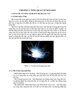
Here's a 555 made with 22 transistors by Malcolm Faed. See his video.
See his Electric Vehicle website.
How are your powers of observation?
Can you find the LED:
THE POWER SUPPLY
Sometimes you will see a circuit as shown in the first diagram with 12v or +12v on
the top rail and 0v or a negative sign or the word "negative" on the bottom rail. In
this case the word negative means earth or "chassis of a car" and we commonly
refer to this as "negative earth" or "negative chassis."
In the second diagram, the output from a power supply has a positive 12 volts and a
negative 12v with the 0v rail in the middle. In this case the negative 12v rail is
twelve volts BELOW the earth rail and that's why we call it the NEGATIVE RAIL.
This means that when you hear "Negative Rail," you need to work out if it means the
negative terminal of a battery (as in the first case - meaning 0v or earth) or if the
voltage is below zero volts (as in the second case).
SQUARE WAVE
OSCILLATOR KIT
A Square Wave Oscillator Kit is available from
Talking Electronics for under $10.00. See full
details of circuit below.
(This link will send an email to Colin Mitchell
and you will be advised of costs and how to
send money via Paypal or credit card.)
Or email Colin Mitchell:
555 KIT
A kit of components to make
many of the circuits described
in this eBook is available for $10.00 plus $7.00
post.
CONTENTS
Active High Trigger
Active Low Trigger
Alarm Sounds (4 sounds)
Amplifier using 555
Animated Display
Audio Frequency Meter
Automatic Curtain Closer
Astable Multivibrator
Battery Charger
Bi-Coloured LED
Bike Turning Signal
Bi-Polar LED Driver
Bi-Stable 555
Building the Circuits
Capacitor Charge Pump
Car Lights Flasher - warning flasher
Car Tachometer
Charge Pump
Clark Zapper
Clicks Uneven
Calculator 555 7555
CMOS 555
Constant Current
Continuity Tester
Curtain Closer
Dark Detector
Dog-Bark Stopper
Dice
Dice to 7-Segment Display
Display - Animated
Divide by 2
Driving A Bi-Coloured LED
Driving A Relay
Driving White LEDs
Music Box
Negative Voltage
Normally Closed Trigger
One-Shot 555
Organ
Police Lights 1,2,3
Police Siren
Powering A Project
Pulse Extender
Pulser - 74c14
Push Pull
Push-Pull - high current
PWM Controller - FET buffer
PWM - transistor buffer
see also Motor PWM
Railroad Lights (flashing)
Railway Time
Rain Alarm
Ramp Generator
Reaction Timer Game
Replacing 556 with two 555's
Replacing TTL 555 with CMOS 555
Resistor Colour Codes
Reversing A Motor
Roulette
Schmitt Trigger
Screamer Siren - Light Controlled
Servo Controller
Servo Tester
Simplest 555 Oscillator
Sinewave Output
Siren 100dB
Solar Tracker - not suitable for 555
Square Wave Oscillator
Duty Cycle 1:1 (50%)
Fading LED
Fastest 555 Oscillator
Flasher
Flashing Indicators
Flashing Railroad Lights
Flip Flop see also Toggle
Four Alarm Sounds
Frequency Divider
Frequency Meter
Function of each 555 pin
H-Bridge
H-Bridge Push-Pull - high current
H-Bridge with PWM
Headlight Flasher - faulty circuit
Headlight Selector
Hee Haw Siren
Higher Sinking Current
High Frequency 555 Oscillator
How to use the 555
Hysteresis
Improving the output of a 555
Increasing Sinking Current
Increasing Output Push-Pull Current
Inverter 12v to 240v
Inside the 555
Jammer for TV
Kitt Scanner
Knight Rider
Laser Ray Sound
Latch
Latch - using transistors
LED Dice
LED Dimmer
LED FX
Light Controlled Screamer Siren
Light Detector
Lights - Traffic Lights
LMC555 CMOS 555
Low Frequency 555 Oscillator
Low Power 555
Machine Gun
Mark-Space Ratio
Memory Cell see also Toggle Flip Flop
Mercury Switch Detector - faulty circuit
Metal Detector
Missing Pulse Detector - faulty circuit
Model Railway Time
Monostable 555
Morse Keyer
Mosquito Repeller
Motor Controller (stepper Motor)
Motor PWM
Stepper Motor Controller
Stun Gun
Substituting a 555 - Part 1
Substituting a 555 - Part 2
Supply (170v) for Nixie Tubes
Switch Debounce
Tachometer
TE555-1 Stepper Motor Controller
Ticking Bomb
Tilt Switch
Toggle 555 see also Flip Flop
Touch Switch
Touch ON-OFF
Toy Organ
Traffic Lights
Traffic Lights - 4 way
Transistor Tester
Trigger Timer - 74c14
Turning Signal
TV Remote Control Jammer
Useless Machine
Uneven Clicks
Up/Down Fading LED
Using the 555
VCO
Voltage Doubler
Voltage Inverter
Voltage Multiplier x10times
Warning Flasher - car lights flasher
Water Level Detector
Wailing Siren
Zapper (Dr Clark)
Zapper - Voltage Multiplier
Zener Diode Tester
2 Minute Timer - 74c14
3x3x3 Cube
4 Alarm Sounds
4 way Traffic Lights
1-10 Minute Auto Turn Off
10 Minute Timer - 74c14
12v DC to 12v DC Battery Charger
12v to 240v Inverter
50% Duty Cycle
100dB Siren
170v Supply for Nixie Tubes
555's - a list of substitutes
555 Amplifier
555 CMOS version LMC555
555 Kit of Components
555 Pinout
555 Pins - Remembering the pins
555 Mistakes (No-No's)
555 on 24v
Multivibrator - Astable
555 Timer Calculator
555 VCO
556 Dual Timer
7555 CMOS Calculator
THE 555 PINS
Here is the identification for each pin:
When drawing a circuit diagram, always draw the 555 as a building block, as shown below with the pins
in the following locations. This will help you instantly recognise the function of each pin:
Pin 1 GROUND. Connects to the 0v rail.
Pin 2 TRIGGER. Detects 1/3 of rail voltage to make output HIGH. Pin 2 has control over pin 6. If pin 2
is LOW, and pin 6 LOW, output goes and stays HIGH. If pin 6 HIGH, and pin 2 goes LOW, output goes
LOW while pin 2 LOW. This pin has a very high impedance (about 10M) and will trigger with about 1uA.
Pin 3 OUTPUT. (Pins 3 and 7 are "in phase.") Goes HIGH (about 2v less than rail) and LOW (about
0.5v less than 0v) and will deliver up to 200mA.
Pin 4 RESET. Internally connected HIGH via 100k. Must be taken below 0.8v to reset the chip.
Pin 5 CONTROL. A voltage applied to this pin will vary the timing of the RC network (quite
considerably).
Pin 6 THRESHOLD. Detects 2/3 of rail voltage to make output LOW only if pin 2 is HIGH. This pin
has a very high impedance (about 10M) and will trigger with about 0.2uA.
Pin 7 DISCHARGE. Goes LOW when pin 6 detects 2/3 rail voltage but pin 2 must be HIGH. If pin 2 is
HIGH, pin 6 can be HIGH or LOW and pin 7 remains LOW. Goes OPEN (HIGH) and stays HIGH when
pin 2 detects 1/3 rail voltage (even as a LOW pulse) when pin 6 is LOW. (Pins 7 and 3 are "in phase.")
Pin 7 is equal to pin 3 but pin 7 does not go high - it goes OPEN. But it goes LOW and will sink about
200mA. You can connect pin 7 to pin 3 to get a slightly better SINK capability from the chip.
Pin 8 SUPPLY. Connects to the positive rail.
555 in a circuit - note the circle on the chip to identify pin 1
This is sometimes called a "push-out-pin" (hole) and sometimes
it has no importance. But in this case it represents pin 1.
THE SIMPLEST 555 OSCILLATOR
The simplest 555 oscillator takes output pin
3 to capacitor C1 via resistor R1.
When the circuit is turned on, C1 is
uncharged and output pin 3 is HIGH. C1
charges via R1 and when Pin 6 detects 2/3
rail voltage, output pin 3 goes LOW. R1
now discharges capacitor C1 and when pin
2 detects 1/3 rail voltage, output pin 3 goes
HIGH to repeat the cycle.
The amount of time when the output is
HIGH is called the MARK and the time
when the output is LOW is called the
SPACE.
In the diagram, the mark is the same length
as the space and this is called 1:1 or
50%:50%.
If a resistor and capacitor (or electrolytic) is
placed on the output, the result is very
similar to a sinewave.
C1 to POSITIVE RAIL
C1 can be connected to the positive rail. This is not normal practice, however it does work.
The output frequency changes when the capacitor is changed from the negative rail to the
positive rail. Theoretically the frequency should not change, but it does, and that's why you
have to check everything. The frequency of operation in this arrangement is different to
connecting the components via pin7 because pin3 does not go to full rail voltage or 0v. This
means all the output frequencies are lower than those in the "555 Frequency Calculator."
The table shows the frequency for the capacitor connected to the 0v rail and 12v rail:
C1 to 0v rail
C1 to 12v rail
1k
1n
505kHz 1k
1n
255kHz
1k
10n
115kHz 1k
10n
130kHz
1k
100n 23kHz
1k
100n 16kHz
10k 1n
112kHz 10k 1n
128kHz
10k 10n
27kHz
16kHz
10k 10n
10k 100n 3700Hz 10k 100n 1600Hz
CHANGING THE MARK-SPACE RATIO
This ratio can be altered by adding a diode and resistor as shown in the following diagrams.
In the first diagram, the 555 comes ON ("fires-up") with pin 3 low and pin 2 immediately
detects this low and makes pin 3 HIGH. The 10n is quickly charged via the diode and 4k7
and this is why the MARK is "short." When the capacitor is 2/3Vcc, pin 6 detects a HIGH
and the output of the 555 goes LOW. The 10n is discharged via the 33k and this creates the
long-duration SPACE (LOW). The second diagram creates a long-duration HIGH:
to Index
HOW TO REMEMBER THE PINS:
THE FASTEST 555 OSCILLATOR
The highest frequency for a 555 can be obtained by connecting
the output to pins 2 and 6. This arrangement takes about 5mA
and produces an output as shown. The max frequency will
depend on the supply voltage, the manufacturer, and the actual
type of 555 chip.
View the output on a CRO. Our 555 "Test Chip" produced a
frequency of 300kHz at 5v and also at 12v. (CMOS versions will
operate at a higher frequency.) Note the very short LOW TIME.
INSIDE THE 555
Note: Pin 7 is "in phase" with output Pin 3 (both are low at the same time).
Pin 7 "shorts" to 0v via a transistor. It is pulled HIGH via R1.
Maximum supply voltage 16v - 18v
Current consumption approx 10mA
Output Current sink @5v = 5 - 50mA @15v = 50mA
Output Current source @5v = 100mA @15v = 200mA
Maximum operating frequency 300kHz - 500kHz
Faults with Chip:
Consumes about 10mA when sitting in circuit
Output voltage can be up to 2.5v less than rail voltage
Output can be 0.5v to 1.5v above ground
Sources up to 200mA
Some chips sink only 50mA, some will sink 200mA
A NE555 was tested at 1kHz, 12.75v rail and 39R load.
The Results:
Output voltage 0.5v low, 11.5v high at output current of 180mA
The "test chip" performance was excellent.
HOW TO USE THE 555
There are many ways to use the 555. They can be used in hundreds of
different circuits to do all sorts of clever things. They can also be used as
three different types of oscillators:
(a) Astable Multivibrator - constantly oscillates
For frequencies above 1 cycle per second, it is called an oscillator
(multivibrator or square wave oscillator).
For frequencies below 1 cycle per second it is called a TIMER or DELAY.
(b) Monostable - changes state only once per trigger
pulse - also called a ONE SHOT
(c) Voltage Controlled Oscillator - called a VCO.
THE ASTABLE (or FREE RUNNING)
MULTIVIBRATOR
The capacitor C charges via R1 and
R2 and when the voltage on the
capacitor reaches 2/3 of the supply, pin
6 detects this and pin 7 connects to 0v.
The capacitor discharges through R2
until its voltage is 1/3 of the supply and
pin 2 detects this and turns off pin 7 to
repeat the cycle.
The top resistor is included to prevent
pin 7 being damaged as it shorts to 0v
when pin 6 detects 2/3 rail voltage.
Its resistance is small compared to R2
and does not come into the timing of
the oscillator.
The following graph applies to the Astable circuit:
Using the graph:
Suppose R1 = 1k, R2 = 10k and C = 0.1u (100n).
Using the formula on the graph, the total resistance = 1 + 10 + 10 = 21k
The scales on the graph are logarithmic so that 21k is approximately near the
"1" on the 10k. Draw a line parallel to the lines on the graph and where it
crosses the 0.1u line, is the answer. The result is approx 900Hz.
Suppose R1 = 10k, R2 = 100k and C = 1u
Using the formula on the graph, the total resistance = 10 + 100 + 100 = 210k
The scales on the graph are logarithmic so that 210k is approximately near
the first "0" on the 100k. Draw a line parallel to the lines on the graph and
where it crosses the 1u line, is the answer. The result is approx 9Hz.
The frequency of an astable circuit can also be worked out from the following
formula:
frequency =
1.4
(R1 + 2R2) × C
555 astable frequencies
C
R1 = 1k R1 = 10k R1 = 100k
R2 = 6k8 R2 = 68k R2 = 680k
0.001µ 100kHz
10kHz
1kHz
0.01µ
10kHz
1kHz
100Hz
0.1µ
1kHz
100Hz
10Hz
1µ
100Hz
10Hz
1Hz
10µ
10Hz
1Hz
0.1Hz
0.001µ = 1n
0.01µ = 10n
0.1µ = 100n
HIGH FREQUENCY OSCILLATORS
360kHz is the absolute maximum as the 555 starts to malfunction with
irregular bursts of pulses above this frequency. To improve the
performance of the oscillator, a 270R and 1n can be added as shown in
the second circuit:
LOW FREQUENCY OSCILLATORS called TIMERS
If the capacitor is replaced with
an electrolytic, the frequency of
oscillation will reduce. When the
frequency is less than 1Hz, the
oscillator circuit is called a timer
or "delay circuit." The 555 will
produce delays as long as 30
minutes but with long delays, the
timing is not accurate.
555 Delay Times:
C
R1 = 100k R1 = 470k R1 = 1M
R2 = 100k R2 = 470k R2 = 1M
10µ
2.2sec
10sec
22sec
100µ
22sec
100sec
220sec
470µ
100sec
500sec
1000sec
The following circuits show a 1-5 minute timer and 10 minute timer:
CMOS 555
A low power version of the 555 is available from many
manufacturers and basically it is a CMOS version of the
TTL 555 device.
The CMOS 555 has the same pinouts as the TTL version
and can be fitted into the same 8 pin socket but if the
circuit needs more current than can be supplied by the
CMOS version, it will not produce the same results.
It is the low current capability of the CMOS version that
will be the major reason why you cannot directly replace
the TTL version with the CMOS version.
It will operate from 1v (only some manufacturers) to 15v
and will work up to 3MHz in astable mode.
Current consumption @5v is about 250uA (1/4mA)
But the major thing to remember is the output current
capability.
At 2v, the chip will only deliver 0.25mA and sink only
1mA.
At 5v, the chip will deliver 2mA and sink only 8mA
At 12v the chip will deliver 10mA and sink 50mA
At 15v the chip will deliver 100mA and sink 100mA
SQUARE WAVE OSCILLATOR KIT:
A square wave oscillator kit can be purchased from
Talking Electronics for approx $10.00
See website: Square Wave Oscillator
It has adjustable (and settable) frequencies from 1Hz
to 100kHz and is an ideal piece of Test Equipment.
(This link will send an email to Colin Mitchell and
you will be advised of costs and how to send money
via Paypal or credit card.)
Bi-stable or "Latch" or "2-state" 555
The bi-stable 555 has two steady states. SET turns ON the LED and
RESET turns the LED off. The 555 comes on in reset mode as Pin2 does
not see a LOW to SET the 555.
See also: Divide By Two
Monostable or "One Shot" or Pulse
Extender
When the circuit is turned on, the output is LOW and a brief negative pulse
on pin 2 will make the output go HIGH for a period of time determined by
the value of R and C. If pin 2 is low for longer than this period, the output
will remain HIGH while pin 2 is LOW and immediately go LOW when pin 2
goes HIGH.
CIRCUIT OPERATION
When the circuit is turned on, the capacitor is uncharged. Pin 6 sees a
LOW and pin 2 sees a HIGH.
Remember: Pin 2 must be LOW to make the output HIGH.
Pin 6 must be HIGH to make the output LOW.
Neither pin is "controlling the chip" at start-up and the chip is designed to
output a LOW with these start-up conditions.
In other words, the chip starts in RESET mode. Pin 7 is LOW and the
capacitor does not charge.
When pin 2 see a LOW pulse, the chip goes to SET mode and the output
goes HIGH. Pin 7 goes OPEN and capacitor C charges via R. When pin 6
sees 2/3 rail voltage, the chip goes to RESET mode with pin 3 and 7
LOW. The capacitor instantly discharges via pin 7 and the circuit waits for
a negative pulse on pin 2.
THE 555 AS A VOLTAGE
CONTROLLED OSCILLATOR (VCO)
By adjusting the voltage on pin 5, (the CONTROL pin) the frequency of the
oscillator can be adjusted quite considerably. See Police Siren for an
application.
THE 555 AS A RAMP GENERATOR
When a capacitor is charged via a constant current, the waveform across
it is a ramp.
to Index
FREQUENCY DIVIDER
A 555 can be used to divide a frequency by almost any division.
It works this way:
A 555 is set-up to produce the required output frequency.
Pin 2 is then taken to the input frequency and this turns the 555 into a
Monostable Multivibrator.
The circuit will detect a LOW on pin 2 to start the timing cycle and pin 3
will go HIGH. The 555 will not respond to any more pulses on pin 2 until
pin 6 detects a HIGH via the charging of the capacitor. The value of C and
the 1M pot need to be adjusted to produce the desired results.
DIVIDE BY 2
A 555 can be used to divide-by-2
When pins 2 and 6 are connected, they detect 1/3 and 2/3 of rail voltage.
When the detected voltage is below 1/3, the output goes HIGH and when
the voltage is above 2/3, the output goes LOW.
The push switch detects the output voltage and after a short period of time
the electrolytic will charge or discharge and it will be HIGH or LOW.
If the switch is pressed for a short period of time, the output will change. If
the switch is kept pressed, the output will oscillate at a low frequency.
"No-No's"s"
Here are some mistakes to avoid:
1. Pin 7 gets connected to the 0v rail via a transistor inside the chip during
part of the operation of the 555. If the pot is turned to very low resistance
in the following circuit, a high current will flow through the pot and it will be
damaged:
2. The impedance of the 100u electrolytic will allow a very high current to
flow and the chip will get very hot. Use 10u maximum when using 8R
speaker. (The temp of the chip will depend on the frequency of the circuit.)
3. The reset pin (pin 4) is internally tied HIGH via approx 100k but it
should not be left floating as stray pulses may reset the chip.
4. Do not draw 555 circuits as shown in the following diagram. Keep to a
standard layout so the circuit is easy to follow.
5. Here's an example from the web. It takes a lot of time to work out what
the circuit is doing:
The aim it to lay-out a circuit so that it shows instantly what is happening.
That's why everything must be in recognised locations.
Here is the corrected circuit: From this diagram it is obvious the circuit is
an oscillator (and not a one-shot etc).
6. Don't use high value electrolytics and high resistances to produce long
delays. The 555 is very unreliable with timing values above 5-10 minutes.
The reason is simple. The charging current for the electrolytic is between
1 - 3 microamp in the following diagram (when the electro is beginning to
charge) and drops to less than 1 microamp when the electro is nearly
charged.
If the leakage of the electro is 1 microamp, it will never fully charge and
the 555 will never "time-out."
7. Do not connect a PNP to the output of a 555 as shown in the following
diagram. Pin 3 does not rise high enough to turn the transistor OFF and
the current taken by the circuit will be excessive. Use an NPN driver.
555's
Here is a list of 555's from different manufacturers plus the range of low voltage, low current
555's. The normal 555 is called a TTL or Transistor-Transistor-Logic chip and it consumes
about 10mA when "sitting and doing nothing." It will work from 4v to 18v.
A low current version is available from the list below, (called a CMOS version) and consumes
about 10uA to 100uA. Some of these chips work from 1.5v to 15v (ZSCT1555 = 9v max) but
they can sink and source only about 100mA (less than 30mA at 2v).
The 555 is the cheapest and the others cost about double.
The normal 555 oscillates up to 300kHz. A CMOS version can oscillate to 3MHz.
You need to know the limitations as well as the advantages of these chips before substituting
them for the normal 555:
Manufacturer
Custom Silicon
Solutions
ECG Philips
Exar
Fairchild Semiconductor
Model
CSS555/CSS555C
ECG955M
XR-555
NE555/KA555
Remark
CMOS from 1.2V, IDD < 5uA
Harris
IK Semicon
Intersil
Lithic Systems
Maxim
Motorola
National Semiconductor
National Semiconductor
NTE Sylvania
Raytheon
RCA
STMicroelectronics
HA555
ILC555
SE555/NE555/ICM7555
LC555
ICM7555
MC1455/MC1555
LM1455/LM555/LM555C
LMC555
NTE955M
RM555/RC555
CA555/CA555C
NE555N/ K3T647
Talking Electronics
TE555-1, -2, -3, -4
Texas Instruments
Zetex
CMOS from 2V
CMOS from 2V
CMOS from 1.5V
email Talking Electronics $2.50
ea
SN52555/SN72555; TLC555 CMOS from 2V
ZSCT1555
down to 0.9V
(9v max)
to Index
REPLACING A 556 WITH TWO 555's
Here is a handy reference to replace a 556 dual timer with two 555's:
The table shows the pin numbering for each timer:
555 556 - Timer 1
Ground (–)
1
7
Trigger
2
6
Output
3
5
Reset
4
4
Control
5
3
556 - Timer 2
7
8
9
10
11