Volume 2 wind energy 2 14 – offshore wind power basics
Bạn đang xem bản rút gọn của tài liệu. Xem và tải ngay bản đầy đủ của tài liệu tại đây (6.05 MB, 38 trang )
2.14
Offshore Wind Power Basics
M Kapsali and JK Kaldellis, Technological Education Institute of Piraeus, Athens, Greece
© 2012 Elsevier Ltd. All rights reserved.
2.14.1
Introduction
2.14.2
Offshore Wind Energy Status
2.14.2.1
History and Background
2.14.2.2
Offshore Wind Energy Activity
2.14.3
Offshore Wind Farms – Basic Features
2.14.3.1
Wind Turbine Design
2.14.3.2
Support Structures and Towers
2.14.3.2.1
Shallow water technology
2.14.3.2.2
Transitional water technology
2.14.3.2.3
Floating technology
2.14.3.3
Supplementary Equipment
2.14.3.3.1
Offshore substation
2.14.3.3.2
Onshore substation
2.14.3.3.3
Underwater cabling
2.14.4
Offshore Wind Farm Design, Installation, and Maintenance
2.14.4.1
Equipment Selection Requirements
2.14.4.1.1
Wind evaluation
2.14.4.1.2
Wave and current evaluation
2.14.4.2
Other Wind Farm Design Considerations
2.14.4.3
Installation and Transportation Facilities
2.14.4.4
O&M Facilities
2.14.5
Offshore Wind Energy Economic Considerations
2.14.6
Environmental and Social Issues
2.14.6.1
Noise Impacts
2.14.6.2
Visual Impacts
2.14.6.3
Impacts on Wild Life
2.14.7
Future Trends and Prospects
References
Further Reading
Relevant Websites
Glossary
Capacity factor Ratio between the real and the potential
electricity production if the wind turbine had operated at
rated capacity.
Conventional power generation Burning coal, oil or
natural gas to generate power.
Fixed bottom structure Mounting the wind turbine’s
tower on the seabed.
Floating concept Mounting the wind turbine’s tower on a
floating platform.
Foundation In this Chapter the term ‘foundation’ refers
only to the part of the installation being actually into the
seabed. However, in some other cases, one may see the
term ‘foundation’ to be used for the whole part of the
installation below the tower of the offshore wind
turbine.
Comprehensive Renewable Energy, Volume 2
432
432
432
434
440
440
441
441
446
449
450
450
451
451
452
452
454
454
455
456
458
459
463
463
463
463
464
466
468
468
Life cycle cost The sum of all recurring and one-time
(non-recurring) costs over the full life cycle of a project.
Broadly speaking, this cost includes the initial investment,
installation costs, O&M costs (split into the fixed
maintenance cost and the variable one), and remaining
(residual) value at the end of the project’s useful life.
Shallow water technology Offshore wind applications
appropriate for shallow water depths (e.g. <30 m).
Support structure The construction between the tower
and the foundation.
Transitional water technology Offshore applications
appropriate for transitional water depths (e.g. between
30 m and 60 m).
Wind farm micrositing The exact determination of
the turbines’ installation positions inside a wind farm’s
site.
doi:10.1016/B978-0-08-087872-0.00217-1
431
432
Offshore Wind Power Basics
2.14.1 Introduction
As has been already described in detail in previous chapters of this volume, in recent years, there has been a spectacular increase
in wind power installations worldwide. Wind power technology is generally considered as a mature and cost-effective means of
achieving future carbon reductions and renewable energy targets, but issues such as the scarcity of appropriate on-land installation
sites and visual and noise constraints often limit its development. As a result, a substantial shift of the focus toward the vast offshore
wind resources has been made and an incipient market has emerged, that is, offshore wind energy.
Offshore wind energy, as implied by the name, concerns the electricity produced by wind turbines placed offshore and
practically in the sea. Offshore wind power comprises a relatively new challenge for the international wind industry with a
demonstration history of around 20 years and a 10-year commercial history for large, utility-scale projects. Currently,
about 3 GW of offshore wind power is installed worldwide, with the majority of projects being located in European
waters. During the year 2010, offshore wind power experienced a record growth with more than 800 MW being installed.
Despite the progress met, however, in the field of offshore wind during the recent years, offshore installations represent at
the moment only a very small percentage of the global wind power capacity, approximately 1.5%. Nonetheless, it is
expected that a considerable part of the future expansion of wind energy utilization, at least in Europe, will come from
offshore resources.
Compared with land-based installations, offshore wind energy has greater resource potential (wind speeds tend to increase
significantly with distance from land) and minimal environmental effects, but marine conditions (weather, winds, waves, and water
currents) pose considerable challenges to project development that require a new approach in terms of wind turbine technology,
support structures, electrical infrastructure, and logistics for installation and maintenance. At present, offshore wind farms require
strong foundations that must be firmly placed into the seabed. Also, many kilometers of cabling are needed to transfer the power
output back to shore, and both construction and maintenance work must be carried out in reasonable weather conditions using
special vessels and equipment. Furthermore, compared with land-based wind power projects, the construction of offshore wind
turbines requires advanced engineering and use of materials that resist corrosive marine environment.
The costs of offshore wind are currently significantly higher than onshore ones and strongly depend on site-specific conditions
such as water depth, distance from shore, and seabed properties. In general, offshore wind power follows the following simple
principle: The further the distance from the shore, the greater the wind resources are, resulting in higher energy production. But
further distance from shore implies greater water depths, which in turn increase the development and operation costs of such
projects.
It should be mentioned that the development of offshore wind power projects has been based considerably on experience
and technology from the oil and gas industry, while the wind turbines used, currently having capacity ratings up to 5 MW,
comprise adaptations from land-based counterparts. In this context, although offshore wind turbine technology has been
evolving at a fast pace over the last few years, there is clearly much that needs to be done. In future, much larger machines,
specifically constructed for offshore use, are envisaged that will likely benefit from economies of scale and result in significant
cost reduction.
All the above issues are extensively analyzed in this chapter. It should be noted, however, that this text has been written on a
scientific basis adjusted to be also equally well-understood by anyone who is interested but is not an expert reader. Since other
chapters cover the fundamental aspects of wind energy, mainly from the point of view of land-based installations, this chapter
intends to present only issues that are different for offshore counterparts. In this context, it is recommended that this chapter is read
in parallel with other chapters of this volume.
2.14.2 Offshore Wind Energy Status
Over the last 20 years, there has been a spectacular increase in wind power installations worldwide. The enormous growth of
the onshore wind energy industry has been accompanied by the growth of offshore wind power technology, especially during recent
years, with several countries (United Kingdom, Denmark, Netherlands, etc.) being the key drivers for its development. In this
section, a review of the offshore global wind energy installations is undertaken, starting from the very first applications up until
today.
2.14.2.1
History and Background
The first documented concepts of offshore wind turbines were developed by Hermann Honnef in Germany in 1932 [1]. The first
concept of large-scale offshore wind farms was developed by Prof. William E. Heronemus off the coast of Massachusetts in 1972 [2],
but they were never installed. Eventually, the first offshore wind power test facility was set up in Sweden in 1990. It was a single wind
turbine of 220 kW rated power, at a distance of 250 m from the coast, supported on a tripod structure anchored to the seabed about
7 m deep.
Offshore Wind Power Basics
433
The first full-scale development of offshore wind power projects was driven largely by commercial aspirations of the European
wind industry, considering the oceans as a feasible solution to the shortage of onshore sites. The first offshore wind farm was
commissioned in 1991 in Denmark and constructed by the utility company SEAS. This small wind farm, which is still in operation,
consists of 11 stall-controlled wind turbines of total rated power 4.95 MW (450 kW each). It is located 1.5–3 km north from the
coast of the island of Lolland, near the village of Vindeby (Figure 1). The total area of the wind farm is 3 km2 and it has gravity-based
foundation structure type. The wind turbines are placed in shallow water, 3–5 m deep, in two parallel rows, with the distance
between each turbine being approximately 500 m. The cost of construction is stated as being approximately €10 million [4].
The world’s second offshore wind farm (Figure 2) was built in 1994 in the Netherlands, at a depth of 5–10 m, with 800 m
average distance from the shore. It consists of four wind turbines of 500 kW each, and the foundation type adopted for this project
is monopile. Just after 1 year, in 1995, the world’s third offshore wind farm (Figure 3) was commissioned between the Jutland
peninsula and the small island of Tunø Knob in Denmark. It consists of 10 wind turbines of 500 kW each, sited 6 km far from the
shore at a depth of 3–6 m. The turbines are placed in two rows, with a distance of 200 m between each turbine and 400 m between
the two rows. The foundation structure of the wind farm is gravity-based type. Each turbine is a horizontal axis pitch regulated
machine, orientated upwind with a tubular tower and a three-bladed rotor of 39 m diameter.
In the following 5 years, relatively small offshore wind power projects of 450–600 kW units rating were installed in the United
Kingdom, the Netherlands, and Sweden, at distances of up to 3 km from the coast and depths of up to 8 m. Multimegawatt wind
turbines appeared later, in a second phase, along with the opportunity of experiencing deeper waters in the sea. In 2001, the
construction of the first large-scale offshore wind farm (Figure 4) of Middelgrunden with a total rated power of 40 MW (20 wind
turbines of 2 MW each) ended 2 km outside of the harbor of Copenhagen in Denmark, where the seabed is situated between 2.5 and
5 m under sea level.
The demonstration project of Middelgrunden in Denmark led the way for two larger offshore wind power projects, that is,
Horns Rev I (160 MW) in 2002 and Nysted (165.2 MW) in 2003. However, the construction costs of these projects were higher than
Figure 1 Vindeby offshore wind farm in Denmark [3].
Figure 2 Lely offshore wind farm in the Netherlands [5]. Photo by Martin Bond.
434
Offshore Wind Power Basics
Figure 3 Tunø Knob offshore wind farm in Denmark. Vestas offshore wind turbines. Still: Bo Hovgaard.
Figure 4 Offshore wind farm outside the harbor of Copenhagen [7].
anticipated, while some unexpected failures occurred, resulting mainly from the turbines’ exposure to harsh wind and wave
conditions. These issues resulted in the deterioration of some of the initial enthusiasm for the expansion of the offshore wind
power market, and thus in 2005 only one new project was installed. Nevertheless, the great efforts made by manufacturers and
developers in order to identify and improve problems associated with this first phase of projects [8] eventually led to 13 new
commercial offshore wind farm installations in 2008 and 2009.
2.14.2.2
Offshore Wind Energy Activity
Since the installation of the first offshore wind power project, both size and capacity of wind turbines have increased considerably
during recent years (Table 1). While at land-based sites the size of wind turbines, in terms of height and rotor diameter, is often
restricted due to visual impacts, these limits are not encountered in marine environments. The experience has grown significantly
so that now many countries are building large, utility-scale offshore wind farms or at least have plans to do so. However, the vast
majority of the existing large-scale commercial projects still use shallow water technology (located at less than 30 m water depth),
but the idea of going deeper is gradually moving closer toward implementation.
Drivers of offshore wind power development vary from country to country, either determined by the availability of high wind
resources or the limitation of land for new onshore installations. As of 2010, about 96% of global offshore wind farms are located
in European waters, with almost 85% of the total installed capacity being located in the United Kingdom, Denmark, and The
Netherlands (Figure 5). The new installations in 2010 (as of September) were more than 800 MW, with the cumulative global
offshore wind power market finally reaching almost 3 GW, presenting a 40% increase over 2009 (Figure 6).
Table 1
Wind turbines’ size and capacity evolution for selected models
Project
Year
Capacity of each turbine
(MW)
Turbine type
Hub height
(m)
Rotor diameter
(m)
Irene Vorrink
Scroby Sands
Nysted
Robin Rigg
Alpha Ventus
1996
2004
2003
2010
2009
0.6
2
2.3
3
5
Nordtank
Vestas V80
Siemens
Vestas V90
Repower/Multibrid
50
60
69
80
92/90
43
80
80
90
126/116
Offshore Wind Power Basics
435
1341.4 MW
50%
40%
Country's share
870.2 MW
30%
20%
246.8 MW
10%
163.4 MW
102 MW
71.8 MW
30 MW
30 MW
15.3 MW
25.2 MW
0.1 MW
2.3 MW
United Kingdom
Sweden
Norway
Netherlands
Japan
Italy
Ireland
Germany
Finland
Denmark
China
Belgium
0%
Figure 5 Cumulative offshore wind power percentage by country (as of September 2010).
3000
850
800
750
New capacity
Cumulative
2500
700
650
2000
550
500
450
1500
400
350
300
1000
250
Cumulative capacity (MW)
Annual capacity (MW)
600
200
150
500
100
50
0
0
1991 1992 1993 1994 1995 1996 1997 1998 1999 2000 2001 2002 2003 2004 2005 2006 2007 2008 2009 2010
Year
Figure 6 Annual offshore wind farm installations.
More specifically, by September 2010, the offshore wind power industry had developed a total of 45 projects, many
of them large-scale and fully commercial in the waters of Belgium, China, Denmark, Finland, Germany, Ireland, Italy,
Japan, The Netherlands, Norway, Sweden, and the United Kingdom. In terms of capacity, by 2010, offshore wind farms
represented 1.5% of the total installed wind power in the world. Table 2 contains information about all offshore wind farm
installations up till now, showing capacity, distance from the shore, and water depth along with the installation year of each
project.
436
Offshore Wind Power Basics
Table 2
Operational wind farms in the world as of September 2010
Average
water
depth
(m)
Average
distance from
shore
(km)
Country
Project
Rated
power
(MW)
Belgium
China
Denmark
Thornton Bank
Donghai Bridge
Vindeby
Tunø Knob
Middelgrunden
Horns Rev I
Samsø
Frederickshavn
30
102
5
5
40
160
23
10.6
20
10
4
3
8
10
20
3
29
10.5
3
6
3
16
3.5
1
6
34
11
10
20
80
10
4
5
3
0.45
0.5
2
2
2.3
2.65
Nysted
Rønland
Horns Rev II
Sprogø
Avedøre
Rødstand II
Kemi Ajos I + II
Ems-Emdem
Breitling
Hooksiel
Alpha Ventus
165.2
17.2
209
21
7.2
207
30
4.5
2.3
5
60
8
1
13
11
2
9
0
3
2
5
30
8
0.1
30
1
0.1
9
1
0.1
0.5
0.5
53
72
8
91
7
2
90
10
1
1
1
12
2.3
2.3/2
2.3
3
3.6
2.3
3
4.5
2.3
5
5
Arklow Bank
Brindisi
Setana
Kamisu
Lely
Irene Vorrink
Egmond aan Zee
Princess Amalia
Hywind
Bockstigen
Utgrunden
25.2
0.08
1.32
14
2
16.8
108
120
2.3
2.75
10.5
15
108
10
5
7.5
2
20
22
220
7
7
10
20
0.2
0.04
0.8
0.1
10
23
10
3
7
7
1
2
7
4
28
36
60
1
5
7
3.6
0.08
0.66
2
0.5
0.6
3
2
2.3
0.55
1.5
Yttre Stengrund
Lillgrund
Vavern
Blyth
North Hoyle
Scroby Sands
Kentish Flats
Barrow-in-Furness
Beatrice
Burbo
Lynn/Inner
Dowsing
Rhyl Flats
Robin Rigg
Gunfleet Sands
Thanet
10
110
30
4
60
60
90
90
10
90
194.4
10
6
7
6
9
6
5
15
45
10
10
4
10
4
1
8
3
9
7
25
5
5
5
48
10
2
30
30
30
30
2
25
54
90
180
173
300
8
5
8
22.5
8
9.5
7
11.5
25
60
48
100
Finland
Germany
Ireland
Italy
Japan
The Netherlands
Norway
Sweden
The United
Kingdom
Number
of wind
turbines
Turbine
capacity
(MW)
Turbine
manufacturer
Year
online
2008
2010
1991
1995
2000
2002
2002
2003
2
2.3
3
2
2
2
3
3
5
3.6
3.6
Repower
Sinovel
Bonus
Vestas
Bonus
Vestas
Bonus
Vestas/Bonus/
Nordex
Bonus
Bonus/Vestas
Siemens
Vestas
Siemens
Siemens
WinWinD
Enercon
Nordex
Enercon
Repower/
AREVA
GE
Blue H
Vestas
Hitachi
Nedwind
Nordtank
Vestas
Vestas
Siemens
Windworld
Enron/GE Wind
Energy
NEG-Micon
Siemens
WinWinD
Vestas
Vestas
Vestas
Vestas
Vestas
Repower
Siemens
Siemens
2001
2007
2010
2000
2003
2003
2005
2006
2007
2007
2009
3.6
3
3.6
3
Siemens
Vestas
Siemens
Vestas
2009
2009
2010
2010
2003
2003
2009
2009
2009
2010
2008
2004
2006
2008
2009
2004
2008
2004
2010
1994
1996
2006
2008
2009
1998
2000
According to official data [9], it is expected that between 1 and 1.5 GW of new offshore wind power capacity will be fully
connected in Europe during 2011. As seen in Table 3, there are 15 offshore wind energy projects (∼4 GW) which are under
construction and they are going to operate within 2011 and beyond. Furthermore, at least 37 projects have been given consent
worldwide, among which many belong to countries without any offshore wind energy activity yet (i.e., the United States, Canada,
and France) [10].
As mentioned above, up till now vast deployment has taken place in Northern Europe, a situation expected to continue for
another 5 years. Before the end of 2014, more than 16 GW of additional capacity is estimated to be installed, with the United
Offshore Wind Power Basics
437
Table 3
Wind farms under construction in the world,
planned to operate in 2011 [10]
Country
Project
Rated capacity
(MW)
Belgium
Belgium
Denmark
Denmark
Germany
Germany
Germany
Germany
Italy
United Kingdom
United Kingdom
United Kingdom
United Kingdom
United Kingdom
Bligh Bank Belwind I
Thorntonbank
Anholt
Frederikshavn
Baltic 1
Bard 1
Borkum West II
Global Tech 1
Tricase
Greater Gabbard 1
Greater Gabbard 2
Gwynt y Mor
London Array
Ormonde
Total
165
144
400
12
48.3
400
400
400
90
288
216
576
630
150
3919.3
Kingdom and Germany being the two leading markets in the world. By 2020, offshore wind power capacity is expected to reach a
total of 75 GW worldwide, with significant contributions from China and the United States [11], while the European target has been
set to 40 GW by 2020 and 150 GW by 2030 [12].
Offshore wind power market is currently dominated by a few companies. On the demand side, 10 companies or consortia account
for all 3 GW of offshore capacity presently in operation. Dong Energy (Denmark), Vattenfall (Sweden), and E.on (Germany) are the
leading operators [11], all being giant European utilities.
On the supply side, Vestas and Siemens (formerly Bonus Energy A/S) are the leading wind turbine manufacturers worldwide
in terms of installed capacity, with more than 2 GW turbines operating offshore (Figure 7), although there are several other
manufacturers who are now developing new offshore wind turbine types which are close to commercial viability [8]. Both Repower
Systems and AREVA Multibrid installed commercial turbines of 5 MW with a pilot project named Alpha Ventus in Germany in 2009.
Sinovel also entered the market in 2009 with SL3000/90, the first offshore wind turbine manufactured in China and installed in the
Donghai Bridge project in Shanghai. More recently, General Electric reentered the offshore wind market with the announcement of
its 4.1 MW direct drive wind turbine, which is still under development [13].
The United Kingdom is the most important player in the offshore wind energy market, with almost 50% of the offshore wind
power installations in the world being located in British waters. It has 12 operating wind farms (as of December 2010) and the plans
for further development are considerable, since more than 2 GW of offshore wind farms are currently under construction and many
more are at approval stage.
Thanet wind farm (Figure 8), which is the world’s largest offshore wind power project up till now, is located in the United
Kingdom’s waters. The wind farm has 100 wind turbines that have a total capacity of 300 MW, enough to power more than 200 000
homes per year. The Thanet project is located approximately 12 km off Foreness Point, the most eastern part of Kent in England.
Planning permission for the project was granted on 18 December 2006. Eventually, the wind farm was officially opened on 23
September 2010 and the total investment for completing the project is in the order of around £780 million (or ∼€874 million based
on present day currency conversion prices, that is, £1 = €1.121) [14]. The project covers an area of about 35 km2, with the distance
between wind turbines being approximately 500 m along rows and 800 m between rows. Each turbine has rotor diameter 90 m
Others
25%
Repower
3%
Vestas
42%
Siemens (Bonus)
30%
Figure 7 Wind turbine manufacturers’ share until September 2010.
438
Offshore Wind Power Basics
Figure 8 Thanet offshore wind power project in the United Kingdom [15].
and is 115 m tall at its highest point, with an average clearance above sea level of about 23 m. Two submarine power cables run from
an offshore substation within the wind farm connecting to an existing onshore substation in Richborough, Kent.
The United Kingdom has also built the demonstration offshore wind farm called Beatrice, consisting of two wind turbines
of 5 MW each. The turbines are placed in a water depth of 45 m at an average distance of 25 km from the shore, representing the
deepest offshore wind turbine site in the world.
Denmark is the pioneer in offshore wind turbine development as it owns the first offshore wind farm in the word (i.e., Vindeby
in 1991). At this time, it has 12 operating wind farms (September 2010), including the second biggest located at Horns Rev in the
North Sea. The Horns Rev II project has rated capacity of 209 MW and consists of 91 turbines located 30 km far from the shore at an
average water depth of 13 m.
Another big project called Rødsand II (Figure 9) was brought online recently (in October 2010) in the Baltic Sea with a generating
capacity of 207 MW. It is located 4 km off the Danish island of Lolland, very close to the east of the existing 166 MW Rødsand I (also
called Nysted, see Figure 10). Rødsand II covers an area of 35 km2 at an average water depth of 9 m and consists of 90 wind turbines
of 2.3 MW each. Each turbine has a hub height of 68 m and a rotor blade diameter of 93 m. The turbines are connected with 33 kV
underwater cables leading to a substation. It should be noted that this project benefits from a perfect offshore combination, that is,
considerable wind energy yield (∼800 GWh per year, supplying 230 000 homes with electricity), closeness to the shore, shallow waters,
and good soil conditions. The total investment for the completion of this project amounts to about €400 million [16].
The Netherlands is the second country immediately after Denmark that developed offshore wind farms. As of September 2010,
the Netherlands has almost 247 MW offshore wind generating capacity, with the biggest wind farm being that of Princess Amalia
(60 wind turbines of 2 MW each), lying approximately 23 km west of the village of Egmond aan Zee, in the North Sea. The wind
turbine towers are placed on monopile foundations at 23 km average distance from the shore in 22 m water depth. The second
Figure 9 Rødsand II offshore wind power project in Denmark [16].
Figure 10 Nysted offshore wind power project in Denmark [16].
Offshore Wind Power Basics
439
largest offshore wind farm in the Netherlands is the project of Egmond aan Zee, with 108 MW rated power (36 wind turbines of
3 MW each). It is located at an average distance from the shore of about 10 km, at a water depth of 20 m. Egmond aan Zee project
started operation in October 2007 and is now generating enough electrical power for about 100 000 Dutch households.
Sweden currently obtains almost 7% of the total offshore wind power installations. The first Swedish and the fifth worldwide
offshore wind farm named Bockstigen has been operating since 1998, 3 km far from the coast of Gotland. It was built as a
demonstration project with 2.8 MW generating capacity (five wind turbines of 550 kW each). Each three-bladed turbine was
installed on a 2.1 m diameter steel monopile foundation grouted into a 2.25 m diameter socket drilled in a 10 m deep hole in the
seabed. While at earlier wind farms, attention was paid on the demonstration of the technical feasibility of offshore wind energy
utilization, Bockstigen aimed at demonstrating its economic viability [17]. During the next decade, Sweden installed four more
projects and as of September 2010 the offshore wind capacity reached almost 163 MW.
China, the world’s largest onshore wind power developer, with a total of about 43 GW wind turbine installed capacity by the end
of 2010, erected the first large-scale offshore wind farm (Donghai Bridge) outside Europe in 2009, adding 63 MW by year-end for a
project that reached 102 MW upon completion in early 2010. Thus, although offshore wind power development in China has been
much delayed, the year 2010 marked the start of the country’s offshore wind power sector’s transition from research and pilot
projects to operational wind farms. Donghai Bridge project (Figure 11) is located on the east side of the Shanghai East Sea Bridge. It
comprises 34 wind turbines of 3 MW capacity, and it is placed at an average distance of 10.5 km from the shore in 10 m water depth.
According to the Chinese Renewable Energy Industries Association (CREIA) [19], China is planning to expand its offshore wind
power installed capacity to 5 GW by 2015 and 30 GW by 2020.
Germany currently obtains almost 72 MW of offshore wind farm installations. Although Germany is one of the front-runners in
the installation of renewable energy assets, the pace toward offshore wind farms was rather slow mainly because of limited coastline
availability, the need to move into deeper waters, and skepticism concerning economic feasibility of such projects. Nevertheless, this
status seems to change as the government has so far granted permission for 20 offshore wind farms with a total capacity of about
7 GW [10] while another 1.2 GW is currently under development (see also Table 3).
As of September 2010, Germany’s only large-scale offshore wind farm is Alpha Ventus (Figure 12), which has been initially launched
as a pilot project by the German government. This wind farm comprises the deepest large-scale operational offshore wind power project
at this time, with an average distance from the shore of about 53 km. It officially began to operate in April 2010. It is situated in the
North Sea, at 30 m average water depth. It consists of 12 wind turbines of 5 MW generating capacity, giving a total of 60 MW. The total
Figure 11 Donghai Bridge wind power project in China [18].
Figure 12 Alpha Ventus wind power project in Germany [20].
440
Offshore Wind Power Basics
Wind Speed at 90 m
mph
m/s
11.5 −12.0
11.0 −11.5
10.5 −11.0
10.0 −10.5
9.5 −10.0
9.0 − 9.5
8.5 − 9.0
8.0 − 8.5
7.5 − 8.0
7.0 − 7.5
6.5 − 7.0
6.0 − 6.5
0.0 − 6.0
25.7 − 26.8
24.6 − 25.7
23.5 − 24.6
22.4 − 23.5
21.3 − 22.4
20.1 − 21.3
19.0 − 20.1
17.9 − 19.0
16.8 − 17.9
15.7 − 16.8
14.5 − 15.7
13.4 − 14.5
0.0 − 13.4
Individuals per square mile
greater than 1000
less than 1
Figure 13 (Left) US population density compared with (right) US offshore wind resource at 90 m above the surface [21].
investment of Alpha Ventus is about €250 million (quite a high specific turnkey cost ≈4150 € kW−1), and by the construction time of the
project, it was the only wind farm in the world using tripods as foundations for supporting six of the turbines [20].
The United States has also ambitious offshore wind energy plans but none is yet implemented. Even though the United States is
among the leaders in land-based wind energy capacity, no offshore wind power projects have been installed to date. However, about
20 projects of more than 2 GW are in the planning and permitting process. Most of these activities are located in the Northeast and
Mid-Atlantic regions, although projects are being considered or approved also in wind-rich areas along the Great Lakes, the Gulf of
Mexico, and the Pacific Coast. The deep waters off the West Coast, however, pose a technological challenge for the near term [8].
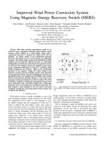
Figure 13 shows the potential offshore wind resources off the US coast compared with the density population. A very interesting
relation may be obtained between these two maps, showing the great possibilities regarding offshore wind energy in the United
States [22]. Specifically, most of the potential offshore wind resources are found relatively close to major urban load centers, where
high energy costs prevail and where opportunities for wind development on-land are limited. This is especially true in the densely
populated northeast, where nearly one-fifth of the national population live on less than 2% of the total land area [23].
2.14.3 Offshore Wind Farms – Basic Features
Most of the current offshore wind energy system designs have been drawn from offshore oil and gas extraction industry and from
land-based wind energy installations. However, the combination of wind, waves, and in some cases ice has introduced a new set of
unique engineering challenges (e.g., construction in the marine environment, towers and foundation design, and electrical transmis
sion) that need to be fully addressed and tested. This section describes the principal components of an offshore wind energy system,
that is, wind turbines, towers, foundations, and additional equipment required for the system’s erection and commissioning.
2.14.3.1
Wind Turbine Design
The wind turbine is the energy producing component and the most visible part of an offshore wind farm installation. The standard
wind turbine type operating today in marine environments consists of a hub and a blade rotor assembly connected through a drive
train to the generator housed in a nacelle (Figures 14 and 15). The most commonly met applications are three-bladed horizontal axis
machines, yaw-controlled, active blade-pitch-to-feather controlled, upwind rotors, with a diameter normally between 90 and 130 m.
Several types of commercial offshore wind energy applications have been developed so far, based on land-based proven
technologies, but with some significant subsystem upgrades. These kinds of systems have special components and characteristics
which must meet the needs of a more remote, harsh, and demanding environment (i.e., ocean conditions). The modifications from
onshore installations include, among others, strengthening the tower to cope with the additional load from waves, incorporating
enhanced corrosion protection systems to keep corrosive salty water and air away from the electrical parts of the wind turbine,
and using warning lights, bright markers, and fog signals to ensure the safety of marine navigation. Also, lightning is generally
considered as more risky offshore, so instead of incorporating systems to ease handling, the wind turbine blades are provided with
better protection, the same used on the most problematic sites onshore.
Offshore wind generators are generally larger than the onshore ones in order to take advantage of the more consistent and
stronger offshore winds. Also, locating wind farms offshore significantly reduces public concerns related to visual impacts, thus
allowing the use of larger machines with greater power output than on-land.
A typical onshore wind turbine today has a tower height of about 60–80 m, while in offshore applications, the height may be
considerably higher with rotor diameters reaching 130 m and even more. Offshore turbines installed today are generally between
2 and 5 MW, but prototypes up to 7 MW are currently being tested, indicating the manufacturing trends about the future wind
turbines operating in maritime environments. Some examples are given in Table 4. This new generation of wind turbines is
intended to acquire innovative operation and maintenance (O&M) concepts and higher technical reliability.
Offshore Wind Power Basics
2
9
20
8
7
19
18
6
17
5
4
16
1
3
15
14
1. Hub controller
4. Oil cooler
7. Parking brake
10. Blade hub
13. Rotor lock system
16. Yaw ring
19. Generator
441
13
12
11
10
2. Pitch cylinder
5. Gearbox
8. Service crane
11. Blade bearing
14. Hydraulic unit
17. Machine foundation
20. Generator cooler
3. Main shaft
6. VMP-top controller
9. Transformer
12. Blade
15. Hydraulic shrink disk
18. Yaw gears
Figure 14 General layout of a horizontal axis wind turbine [24].
2.14.3.2
Support Structures and Towers
Offshore, the climate is considerably different from onshore, winds are less turbulent but stronger, and wind shear (i.e., the change
in wind velocity resulting from the change in elevation) is lower; thus, shorter towers may be used than those in land-based
applications for the same output. Offshore wind turbines are generally mounted on tubular steel or lattice towers (with a special
offshore coating to withstand the harsh marine environment), which are fixed to a foundation so that turbines can capture winds
well above the water’s surface.
The selection of the offshore wind turbine support structure is based on site-specific conditions. Water depth, wind/wave
conditions, currents, seabed properties (i.e., natural or man-made obstructions, slopes, stability, composition, etc.), and access
requirements are the basic parameters affecting the design of the foundation type to be used.
So far, there is not a standard foundation type suitable for all kinds of seabed conditions. Various foundations have been used up
till now (Figure 16), with the most common types being the monopile and the gravity-based one, both employed in shallow waters.
Note that shallow water depths range between 0 and 30 m, transitional depths between 30 and 60 m, while beyond that point deep
water concepts are introduced (see Figure 17). Thus, generally speaking, the support structures of offshore wind turbines may be
classified into three main groups, that is, shallow water, transitional, and floating. Nevertheless, the latter type is still into the
prototype phase and may be feasible as a future option in deep waters. Figure 18 summarizes the main support structures for
offshore wind turbines in terms of maturity and water depth.
2.14.3.2.1
Shallow water technology
As mentioned above, today, the majority of offshore wind power projects are located in shallow waters between 5 and 20 m
(see also Table 2) and employ fixed bottom structures suitable for small to moderate depths. The basic concepts and some
installation details of the main foundations in shallow waters such as monopiles, gravity based, and suction buckets are
presented in the following.
2.14.3.2.1(i) Monopile foundation
A monopile (Figure 19) is a giant steel tube which is normally used in waters up to 30 m deep. It comprises the simplest and the
most commonly employed foundation solution up till now mainly due to its low cost, the minimal footprint on the seabed, and
low design requirements for transition from onshore to offshore. Besides, the installation of a monopile does not generally entail
advanced techniques or significant preparation of the seabed as it is usually hammered into the ocean floor. The relatively simple
shape of monopile keeps its construction cost down but calls for a large tube diameter of up to 6 m. The total weight of the structure
may be more than 500 t. For the sake of reference, this type of foundation has been successfully installed at the 180 MW Robin Rigg
project in the United Kingdom (Figure 20) and at the 160 MW Horns Rev I project in Denmark.
442
Offshore Wind Power Basics
The Horns Rev Turbine
Elevation above
sea water level
110 m
Red blade tips
Rotor
40 m
Pitchable blades
Wind measurements (anemometers)
Aviational lights
Heli-hoist platform
70 m
Hub
Nacelle
Yaw bearings
Cable
61 m
Tower
Personal lift
Accommodation
Ladder
Electrical equipment
Tower door
Navigational lights
Platform
9m
9m
Boat landing
Foundation
6.5−13.5 m
0m
22−24 m
Sea bed
Transition piece
Corrosion protection
Scour protection
(2 layers of stones)
Tube for cable
Cable protection
Trenched cable with optical fiber
cable (connects the turbine to
neighboring turbines or substation)
Driven steel pile
4m
Figure 15 Principal components and dimensions of an offshore wind turbine [25].
Offshore Wind Power Basics
Table 4
Current offshore wind turbine types (as of September 2010) [26]
Manufacturer
Rated capacity
(MW)
Hub height
(m)
Rotor diameter
(m)
Status
AREVA Multibrid
BARD
BARD
GE
Nordex
Nordex
Repower
Repower
Siemens
Siemens
Sinovel
Sinovel
Vestas
Vestas
Vestas
WinWinD
5
6.5
5
4.1
2.3
6
5
6
3.6
2.3
6
3
7
3
3
3
90
90
90
Site specific
70/80/100/105
Unspecified
90–100
85–95
90
Site specific
Unspecified
80/90/100/110
Site specific
Site specific
Site specific
80/88/100
116
120
122
113
90
150
126
126
120
93
128
122
164
112
90
90/100/103/109
Commercial
In progress
Commercial
In progress
Commercial
In progress
Commercial
In progress
Commercial
Commercial
In progress
Commercial
In progress
Commercial
Commercial
Commercial
Gravity foundation
Tripod foundation
Monopile foundation
Figure 16 Overview of the main types of offshore support structures installed today [16].
Land based
Shallow water
<30 m
Transitional water
30−60 m
Deep water
>60 m
Proven technology
Figure 17 Substructure technology classes for offshore wind turbines [8].
Demonstration
Jacket foundation
443
Offshore Wind Power Basics
Monopiles
Mature
444
Gravity based
Developed
Maturity
Jackets
Tripiles
Tripods
Developing
Floating
Suction buckets
Shallow water
30 m
Transitional water
60 m
Deep water
Figure 18 Main support structure technology in relation to water depth.
Work platform
Tower
Intermediate
platform
Boat landing
External J tubes
Substructure
Transition
Grouted
Scour
protection
Monopile
Figure 19 Monopile foundation [27].
Figure 20 Robin Rigg wind power project in the United Kingdom [16].
Foundation
Offshore Wind Power Basics
445
Transition piece
Brackets for
temporary support
before grouting
Grout
Monopile
Gaps and stresses
caused by deformation
in the transition piece
and monopile*
*Please note that deformation and gap sizes
shown have been significantly enlarged for
illustration purposes only and are not true to
scale to actual events.
Figure 21 Grouted connection with gaps [28].
In case that the monopile is hammered into the seabed, the tube rests in the soil and a transition piece connects the support
structure with the wind turbine tower (see Figure 21). Nevertheless, the transition piece represents a significant weakness of the
monopile concept. As the tower vibrates over the years due to the dynamic loads from wind and waves, the grout (i.e., the material
which is often used to connect the monopile with the transition piece) crumbles and must be refilled.
The only way to reduce the risk of grout crumbling is to employ a conical design concept for the transition piece [28] or to drill
the monopile directly into the soil without the use of a transition piece [29]. However, the second choice is rarely used, due to the
high cost associated with it. Drilling is an option only in case where hammering the monopile down is prohibitive due to unsuitable
conditions of the soil.
Although monopile foundation is an appropriate choice for many projects located up to 30 m depth, in deeper waters it may be
inapplicable. As a rule of thumb, going deeper implies increase in the wave, wind, and current loading of the structure. On top of
that, the higher performance of the wind turbines, which is normally encountered in such cases, indicates the installation of larger
machines with greater diameters and thus the implementation of more complex designs (e.g., tripods, jackets, or floating) to
support the structure. The required size of the monopile increases disproportionately with the size of the wind turbine, a condition
that may lead to technoeconomic unfeasible results.
2.14.3.2.1(ii) Gravity-based foundation
The gravity-based foundation comprises an alternative solution employed in shallow waters up to 20–30 m. Eleven concrete
gravity-based structures, each one weighing an average of 908 t, were used to hold the wind turbines of the first offshore wind
farm in the world, Vindeby in Denmark.
Today, gravity-based structures are still constructed in the same way. The basic difference with the monopile is that this type of
foundation is not drilled or hammered into the seabed but rests on the top of the ocean floor. It is simply a large and heavy mass of
material, normally the caisson of reinforced concrete, steel, or a composite. However, depending upon site geologic conditions, this
foundation may require significant seabed preparation before its installation, for example, dredging, gravel, and scour protection
(measures taken in order to avoid soil erosion).
These structures are constructed almost entirely onshore and they are transported on barges to the site of installation. They are
lifted using heavy cranes, sunk, and filled with ballast to increase their resistance to loads. While these kinds of structures can weigh
several hundred and even thousand tons, they can last up to 100 years without any significant maintenance requirements.
Figure 22 shows the installation of a gravity-based structure in the Rødstand II project in Denmark. This kind of structure has
also been deployed successfully at projects such as the 165.2 MW Nysted and 23 MW Samsø in Denmark and more recently at the
Thornton Bank in Belgium.
2.14.3.2.1(iii) Suction bucket foundation
While the suction bucket foundation concept has been widely used in practice in the oil and gas industry, it has not yet been used
commercially as an alternative to support wind turbines offshore in shallow waters. However, a lot of research effort [30, 31] has
been put on it, showing that this technology may be applied equally well as an offshore wind turbine foundation solution.
446
Offshore Wind Power Basics
Figure 22 Installation of a gravity-based support structure at Rødstand II project in Denmark [29].
Figure 23 Suction bucket foundation [8].
Suction bucket foundation consists of a vertical steel skirt extending down from a horizontal base resting on the soil surface, as
illustrated in Figure 23. The bucket is installed by means of suction. It is placed initially on the ocean floor with its self-weight
providing a seal between the skirt tip and the soil. Then, further penetration is achieved by pumping out the water through an
opening in the top lid of the bucket. The resulting differential pressure created between the inside and outside of the bucket forces it
downward into the desired depth of the soil [32].
2.14.3.2.2
Transitional water technology
Transitional or intermediate water technology is used to support wind turbines at depths between 30 and 60 m. Generally, the
advantage of employing wind turbines in these areas is that the visual impacts are minimized and wind generators demonstrate
higher performance compared with shallow water sites. Due to the design adopted and the characteristics of such structures, the
Offshore Wind Power Basics
447
alternating tensile and compressive loads applied on their elements (e.g., piles) are less than those met at a compact foundation
(e.g., monopiles and gravity based), a fact which makes them suitable for greater depths. However, transitional structures imply
higher costs and a more difficult installation process but comprise a step toward floating systems and exploitation of the full wind
resource met in deep waters. Current transitional water technology may be classified into three main types, that is, jacket, tripod, and
tripile support structures.
2.14.3.2.2(i) Jacket support structure
The jacket structure is a design commonly applied by the oil and gas industry for supporting rigs offshore, at water depths much
greater than 100 m. A jacket is made up of four legs of more than 1 m diameter connected to each other with bracings (Figure 24). It
also consists of a working platform, corrosion protection system, cables, and ladders. After a thorough preparation of the seabed, the
legs are usually attached to the ground using piles to secure the structure but gravitation bases or suction anchors may also comprise
a possibility [29].
The first successful attempt of installing a jacket structure was made quite recently, in 2007, in the Beatrice demonstrative project
in the United Kingdom, at a water depth of 45 m. The latest in the world on jacket structures is the Alpha Ventus project in Germany,
in 2009. This is the largest project installed in transitional waters so far. Although the average water depth on-site is almost 30 m, the
project employs six 5 MW wind turbines on jackets and six 5 MW wind turbines on tripods. Figure 25 shows the transportation on a
barge of three from the six jackets used in the Alpha Ventus project.
2.14.3.2.2(ii) Tripod support structure
This structure got its name from the tripod well known to everyone, used by photographers. In offshore sites, however, it comprises
a new and a rarely used concept so far. The whole structure is made of steel and consists of a central cylindrical section, bracings, and
three supporting pile sleeves (Figure 26). Once the tripod is transported to the site of installation, the structure is lowered to the
seabed and a pile is driven through each sleeve. For securing the structure to the seabed, the connection between the pile and
the sleeve is filled with grout or concrete. Tripod structures’ manufacture is relatively complex and time consuming, while the
transportation and installation processes require large barges and heavy lifting cranes.
Figure 24 Jacket structure [29].
Figure 25 Jacket structures on their way to the site of Alpha Ventus [29].
448
Offshore Wind Power Basics
Figure 26 Tripod structure details [29].
The first and so far the last implementation of tripod structures has been in the Alpha Ventus offshore demonstration project. Six
tripods weighing 710 t each with 45 m height were placed on 40 m long piles into the seabed to support six of the project’s wind
turbines (Figure 27). The triangular area of the tripods covers an overall area of 255 m2 [33].
2.14.3.2.2(iii) Tripile support structure
The tripile comprises also a new type of supporting structure developed for offshore wind turbines. It consists of a single beam and
three steel piles, which sit on a three-legged structure above the water’s surface (Figure 28). The three legs are connected to the tower
structure with a transition piece using grouted joints.
Figure 27 Left: The tripod structures used in Alpha Ventus project. Right: A floating crane lifts the 710 t tripod onto the anchoring area and sets it down
on the seabed [33].
Offshore Wind Power Basics
449
Figure 28 Left: Tripile structures [34]. Right: BARD 1 offshore wind farm in Germany [35].
The first tripile test support structure was installed in 2008, in the Hooksiel 5 MW project, in Germany. Also, the large-scale
400 MW offshore wind farm BARD 1 (Figure 28), which is presently under construction in Germany, employs this technology.
The project is located in the North Sea, about 90 km northwest of the island of Borkum at 40 m water depth covering an area of
60 km2 [35].
2.14.3.2.3
Floating technology
The fixed bottom foundation concepts discussed up to now are suitable for shallow to transitional or intermediate water depths of
up to approximately 60 m. At deeper water sites, the above structures are inapplicable because as depth increases, loading also
increases and this requires larger fixed bottom structural dimensions which are economically nonviable. In this context, a floating
concept (i.e., mounting a wind turbine’s tower on a floating platform) instead of a fixed bottom foundation may be a better choice.
Nevertheless, floating wind turbines are still immature and are associated with increased technical risk, which tends to drive costs
upward. For that reason, a lot of research effort has been put on developing a feasible concept [22, 36, 37], with a number of
possible offshore wind turbine platform configuration permutations in terms of available anchors, moorings, buoyancy tanks, and
ballast options being under investigation by the offshore industry [38].
Generally, the major advantages of moving deeper and developing floating systems are as follows:
•
•
•
•
•
Higher and steadier wind speeds improve the energy performance of wind turbines.
Steadier winds cause less wear on the wind turbine.
There is reduced impact on ecosystems and humans (e.g., visual disturbance is nullified).
There is greater potential for full system fabrication at shipyards and transportation to the site in one piece.
The potential locations for installing such systems are increased since there is no depth limitation.
Typically, floating wind turbines are held in place by wires or chains anchored on the ocean floor with piles or suction anchors.
However, the final design of a floating configuration and the selection of the most appropriate solution may vary significantly
depending on a large number of parameters (e.g., mooring system cost and deployment complexity, on-site installation require
ments, soil conditions, maintainability, and related costs). Generally speaking, one may classify floating structures into three main
types (see Figure 29) based on the strategy used to ensure static stability [39], that is,
1. Ballast stabilized. Positioning and stabilization of the platform is achieved with the use of ballast weights attached below a
buoyancy tank. Catenary mooring drag-embedded anchors are used to keep the platform in place [40, 41].
2. Mooring line stabilized. Positioning and stabilization of the platform is reached through prestressed mooring lines anchored to the
seabed by suction piles. The prestressing of lines is used for stabilizing the wind turbine in heave, pitch, and roll [42].
3. Buoyancy stabilized. Positioning and stabilization of the platform is reached through the use of distributed buoyancy. The wind
turbine stands on a platform which floats on the water surface and is held in place by mooring lines [42, 43].
The world’s first full-scale floating wind turbine ‘Hywind’ (Figure 30) was installed in 2009 off the Norwegian coast by the oil
company StatoilHydro at an average water depth of 220 m. The ‘Hywind’ concept incorporates a 2.3 MW wind turbine with 82.4 m
rotor diameter manufactured by Siemens. The floating structure is a ballasted spar type consisting of a steel cylinder filled with a
ballast of water and rocks. It extends 100 m beneath the sea’s surface and is attached to the seabed by a three-point mooring spread.
The primary intention for ‘Hywind’ is to test the performance of the structure and once this has been successfully achieved, Statoil
will work on commercializing the concept for up to 700 m water depths. Furthermore, it should be mentioned that Statoil invested
around 400 million kroner (or around €54 million) in the construction and further development of the pilot project and in research
and development (R&D) related to the specific wind turbine concept [45]. This cost, however, seems unreasonably high, but
this project is the first of its kind and its demonstrative nature required a lot of R&D and monitoring of its operational behavior.
Future cost projections by StatoilHydro indicate that this will change in the near future and the floating concept will compete with
the fixed bottom one.
450
Offshore Wind Power Basics
Floating wind
turbine concepts
Ballast stabilized
''spar-buoy''
with catenary mooring
drag-embedded anchors
Mooring line
stabilized
tension leg
platform with
suction pile
anchors
Buoyancy stabilized
''barge'' with catenary
mooring lines
Figure 29 Floating support structure concepts for offshore wind turbines [39].
Figure 30 First deepwater floating wind turbine [44].
2.14.3.3
Supplementary Equipment
Except for the rotor/nacelle assembly and the support structure employed for an offshore wind power project, there exist additional
elements such as an electrical collection system, transmission cables to the shore, and substations.
2.14.3.3.1
Offshore substation
On-site offshore substations are used to reduce electrical line losses and improve the overall electrical efficiency by increasing the
voltage level (e.g., to 100–220 kV) from the collection system (see below) and then exporting the power to the shore. Apart from
locating the lines from the collection system at a central point and transforming the energy produced to high voltage, the substation
contains the necessary switching panels and other electrical facilities (e.g., power factor correction systems). The substation normally
rests on a monopile or gravity-based foundation and may be also used as a service platform for the wind power plant with a boat
docking facility and a helicopter landing station.
Typically, an offshore substation is installed in cases where the project is in the range of tens of megawatts, located quite far from
shore, and the connection to the electric grid is not at the collection voltage. Nevertheless, a lot of the projects met today do not serve
the above criteria, so they do not incorporate an offshore substation. Figure 31 shows three central offshore transformer substations
located in large-scale wind farms operating today in Denmark and the United Kingdom. Note that to date, no standard substation
layout has yet evolved.
Offshore Wind Power Basics
(a)
(b)
451
(c)
Figure 31 (a) Project Nysted in Denmark, 165 MW, tide range < 1m, low wave height. (b) Project Horns Rev I in Denmark, 160 MW, tide range 5 m,
medium wave height, with helideck. (c) Project Barrow in the United Kingdom, 90 MW, tide range 10 m, high wave height [46].
2.14.3.3.2
Onshore substation
The role of an onshore substation is to forward the energy produced by the offshore wind farm to the electric power grid. Its design is
mainly determined by the network operator and it typically consists of switchgear, metering, transformers, and associated plant. For
projects not very far from shore, it may be possible to connect the collection system directly with an onshore substation instead of
employing an offshore one.
2.14.3.3.3
Underwater cabling
Electrical cabling is divided into two main types, that is, collection and transmission (Figures 32 and 33), with its length being a
major determinant in the setup cost of the project.
The power output of the wind farm is delivered to the offshore substation through interturbine (array) cables (or collection
system). The cables are typically rated at 30–36 kV and are designed to connect multiple wind turbines by forming a string
(collection circuit) before feeding the project’s offshore substation. Then, the transmission of the power to the mainland grid is
achieved with export cables of similar design with the collection system but with higher voltage (usually 100–220 kV). Typically,
each collection and export circuit may be rated up to 3 and 150–200 MW, respectively. Suitable technologies for insulation of cables
include cross-linked polyethylene, self-contained fluid-filled insulation, and ethylene propylene rubber.
The high level of reliability of subsea cables over a long period is ensured by safe laying and burying into marine floor by means
of water jetting, air-lifting, excavating, and rock-sawing. The greatest damages of subsea cables come from ships’ anchors, fishing
gear, and exposure to mobile sand waves which can uncover a buried cable within a few days. In order to avoid the above hazards,
cables are buried at least 2 m deep into the sea floor.
Offshore substation
Transmission to the shore
Collection system
Figure 32 Schematic representation of underwater cabling.
452
Offshore Wind Power Basics
Figure 33 Underwater cable with optic fiber option [47].
2.14.4 Offshore Wind Farm Design, Installation, and Maintenance
Offshore, the methods adopted for wind farm design, installation, and maintenance are fairly different from onshore, with great
attention being given to issues concerning operation reliability, cost-effectiveness, and access. Capital costs are significantly higher
than onshore, as well as risks, thus making the design procedure of a project and the selection of the suitable equipment critical with
no room for mistakes.
In this context, not only the installation of an offshore project comprises a more difficult and more expensive task than onshore,
but also the accessibility for maintenance purposes poses additional concerns. The harsh environmental conditions met in offshore
sites may be the reason for the wind farm to be inaccessible by any transportation means for a long period of time. But even when
the weather permits access to the project, maintenance cost is significantly higher than the equivalent work onshore. Specifically,
O&M costs may be up to 3 times higher than those of land-based systems [48], exceeding 20% of the total life cycle cost of these
projects [49]. For that reason, high operational reliability and adequate maintenance capability are both considered crucial for the
technical and economic feasibility of offshore wind farms. The following section presents the key aspects concerning the offshore
wind farm design, installation, and maintenance.
2.14.4.1
Equipment Selection Requirements
According to relevant international guidelines and standards (see corresponding chapter of this volume for further information)
developed by several bodies and institutions (e.g., Germanischer Lloyd [50], BSH [51], and Det Norske Veritas [52]) concerning the
design and construction of wind farms in offshore sites, the entire system – wind turbine, tower, support structure – is designed by
taking into account the following:
– local environmental conditions (e.g., water depth, seabed features),
– loading (wind, wave, current), and
– long-term operational behavior.
Furthermore, the IEC 61400-3 international standard ‘Design Requirements for Offshore Wind Turbines’ provides the parameters
that should be considered during the design in order to ensure the safety of systems and components of offshore wind turbines,
inclusive of their support structures.
The most critical decision during the development of an offshore wind farm project is the selection of the site and the evaluation of
local resources and conditions driven by technical feasibility constraints, economics, and regulatory issues. On top of that, the selection
of the site largely affects the selection of a suitable wind turbine model and likewise the substructure and the foundation to be employed.
Therefore, the selection of the wind turbine model is carried out in an early stage of the project development so as to determine the
design and the selection criteria of the rest of the components of the wind farm (support structures, electrical infrastructure, etc.). Besides,
offshore wind turbines are usually large in terms of capacity, so the selection is often limited to few commercially available models and
it is based on efficiency, controllability, loading, reliability, serviceability, and maintainability criteria.
Offshore Wind Power Basics
453
Similarly, the selection of support structures for the wind turbines depends on factors such as site-specific conditions, available
technology, and applicability. Specifically, the support structure concept is primarily determined by the water depth and subsoil
conditions, that is, if a shallow (e.g., monopile), transitional (e.g., tripile), or deep water (e.g., floating) technology is most suitable
to be employed and if measures for preparation or further improvement of the soil need to be taken. Therefore, extensive on-site
investigations are necessary in order to ascertain the seabed characteristics at each wind turbine location.
More specifically, on-site investigations require careful planning and include a combination of both geophysical and geotech
nical measurements, which are the key determinants for the selection of the size and the type of the underwater structure. The
geophysical investigation comprises the determination of water depth and seismic properties of the underlying soil layers through
the use of remote sensing technology, often multibeam sonar and/or high-resolution seismic reflection. Accordingly, the geotech
nical measurements are carried out with the use of cone penetrometers or borehole testing for identifying the physical properties of
the seabed into which the foundations are to be installed.
Furthermore, a parameter that is also considered during the selection of suitable support structures is the available construction
and installation technologies. For instance, the prefabrication of a large number of foundations on-land requires the availability of
advanced construction and storage facilities as close as possible to the project’s location so as to minimize transportation costs through
the sea. Also, maintainability and decommissioning issues after the end of the project’s lifetime (e.g., 20 years) are taken into account.
Except water depth and seabed characteristics, the determination of stochastic environmental conditions such as wind, waves,
and currents is important not only in defining the loading forces imposed on a wind turbine’s structural components but also in the
design process of an offshore wind farm in terms of its long-term energy performance. At this point, it should be mentioned that an
analysis of the mechanical–dynamic loads for offshore wind turbines’ structural components is undertaken in the corresponding
chapter of this volume, where one may obtain further information. However, for the sake of reference, one may categorize the
primary loads for an offshore wind turbine and its support structure as follows (see also Figure 34):
•
•
•
•
•
•
•
•
•
Aerodynamic loads
Hydrodynamic loads
Gravitational loads
Inertial loads
Control loads
Mooring system loads
Current loads
Ice loads
Soil interaction loads
Wake turbulence
Turbulent
wind
Lightning
and icing
Gravity
Waves
Ship and ice
impact
Tidal and storm surge
depth variation
Marine
growth
Buoyancy
Earthquake
Figure 34 Loading sources for an offshore wind turbine [39].
Scour
Soil
mechanics
Currents
and tides
454
Offshore Wind Power Basics
2.14.4.1.1
Wind evaluation
As mentioned above, data concerning on-site wind conditions are important not only in determining the loading forces on a wind
turbine’s rotor and nacelle assembly but also in predicting the amount of future electricity production from wind generators, which
will allow evaluation of the economic viability of a project. Furthermore, the knowledge of on-site analytical wind resource data
dictates to a large extent the design of the layout of the plant as it depends not only on technical and cost parameters but also on the
predicted energy production.
Generally speaking, among the most significant meteorological statistics that should be obtained when evaluating a candidate
site are the wind speed time series (on hourly and 10-min basis, in preference at hub height), wind speed and direction probability
density distributions, wind shear, turbulence intensity, and extreme wind gusts. In order to retrieve the above information, accurate
field data, mapping, or databases are essential, depending, however, on the phase of the project development.
Specifically, one should either employ a meteorological mast or utilize offshore databases, including meteorological buoys,
remote sensing devices (e.g., light detection and ranging – LiDAR – and sonic detection and ranging – SODAR), and observation
platforms, for assessing potential offshore wind project sites and establishing zones of prioritized activity. Furthermore, the ‘Wind
Atlas Analysis and Application Program’ (WAsP) [53, 54] can be used for predicting wind statistics on the basis of conventional
weather observations and orographic and topographic information [55]. In addition, mesoscale modeling (validated in conjunc
tion with accurate long-term measurements) and earth satellite imagery data may be used in case of a preliminary assessment of the
long-term wind regime at the area under investigation [56, 57]. However, most of the above methods are associated with a notable
degree of uncertainly in wind and energy production estimations that should be considered.
Offshore measurements with meteorological masts are taken in an advanced phase of the project development as they comprise
the most accurate and effective methodology for obtaining wind resource information although they are very costly (varying
between €1 and 5 million). This high cost depends largely on the construction of the support structure for the meteorological mast
and is almost 100 times more than it would be on-land [58]. So, unlike the typical onshore methods applied for obtaining wind
data, offshore measurements are rather difficult for a large number of sites due to their high cost. However, at great distances from
the shore where there is normally absence of topography (e.g., obstacles and mountains), recordings from one meteorological mast
may be used for a much wider offshore area than onshore.
Once adequate wind speed data are available (∼3–5 years), the estimation of the electricity generation of a wind power plant
in an offshore site is the same as for onshore projects determined by the specific power curve of the employed wind turbine type
(see Chapter 2.06).
In general, offshore winds are less turbulent than onshore and the wind shear is less. In this context, it should be noted that, in
offshore sites, wake losses may be higher than onshore, due to lower ambient turbulence levels, so the careful layout design of a
project is essential. On the other hand, offshore winds blow stronger and more uniformly than on-land, resulting in a higher annual
energy production, with capacity factors (i.e., ratio between the real and the potential electricity production if the wind turbine had
operated at rated capacity) exceeding 40% in many cases [59]. At this point, it should be mentioned, however, that there is a
remarkable possibility for a wind turbine to be out of order for a quite long period of time and the required maintenance work to be
delayed due to difficult access in bad weather conditions (e.g., ice formation in the sea water and waves with great height), a fact
which results in lower capacity factor values than the above mentioned. In this context, improved accessibility (e.g., employing a
helicopter landing station to facilitate access to major wind turbine components during these extreme weather events) comprises a
critical factor to the design of an offshore wind farm.
2.14.4.1.2
Wave and current evaluation
The design of offshore wind farms requires also the evaluation of long-term wave and current conditions, primarily not only due to
their effect on the turbines’ support structures and towers but also due to accessibility considerations of vessels during construction
and maintenance facilities.
In general, the creation of waves at open sea occurs when wind is blowing across the water surface. As wind speed increases, wave
heights increase too, although there may be a time lag, so that extreme winds and waves do not absolutely coincide. Analytical
measurements of offshore wave conditions include the following [60, 61]:
• Significant wave height (SWH) and period. SWH is the average height (trough to crest) of one-third of the largest waves
(see Figure 35).
• Wind-wave direction, height, and period. Wind-waves are produced by local wind. If a swell is present, these waves arrive at a lower
period (more frequently) than do the swells. Wind-wave height is the average height of the highest one-third of the wind-waves.
Wind-wave period is the peak period in seconds of the wind-waves.
• Swell direction, height, and period. Swells are waves not produced by the local wind and come in at a higher period (longer wave
length) than waves produced by the local wind. Swell height is the estimated average height of the highest one-third of the swells.
Swell period is the peak period in seconds of the swells. If more than one swell is present, this is the period of the swell containing
the maximum energy.
• Steepness. For a given wave height, steep waves represent a more serious threat to capsizing vessels or damaging marine structures
than broad swell. Steepness is determined by examining the SWH and the dominant wave period when compared with
climatology.
Offshore Wind Power Basics
455
Statistical wave distribution
Most probable H
Increasing number of waves
Mean H (H)
Significant H (Hs)
Highest one-tenth
of waves (H1/10)
1/3 of waves
Increasing wave height
©The COMET Program
Figure 35 Statistical distribution of ocean wave heights [62].
Currents are generally produced by tides, differences in temperature, rain, runoffs, ocean bottom topography, and the wind (near‐
surface currents). Currents can cause sand wave transport and foundation scouring and affect seabed characteristics and vessel
motion during construction or maintenance activities of the offshore wind farm.
Measurements of waves and currents are carried out using different techniques and equipment, depending much on the special
needs of a project (cost, accuracy required, duration, etc.). Measuring methods are [61, 63] (see also Figure 36) as follows:
A. Acoustic Doppler current profiler (ADCP). It provides a robust means of estimating wave direction and height in both shallow and
deep waters.
B. A directional buoy. It measures near‐surface waves and currents.
C. An array of pressure sensors. It measures near‐surface waves.
D. An ultrasonic device. It measures near‐surface waves upward.
E. An echo sounder. It measures near‐surface waves from above.
F. Wave radar. It measures ocean waves and currents.
G. Remote sensing synthetic aperture radar. It comprises a microwave instrument producing high-resolution imagery regardless of
clouds, dusty conditions, and solar illumination. It measures near‐surface currents and wave fields.
2.14.4.2
Other Wind Farm Design Considerations
Offshore wind farm micrositing (i.e., the exact determination of the turbines’ installation positions inside a wind farm’s site) if not
designed properly can have a significant effect on the project’s energy and economic performance. On top of the above-described
issues (access, wind, and wave loading on wind turbines and support structures), there are many more that should be considered
G
F
Metmast
D
B
Sea level
E
Current
C
Figure 36 Different measurement methods [61].
A
Seabed