Volume 6 hydro power 6 18 – recent achievements in hydraulic research in china
Bạn đang xem bản rút gọn của tài liệu. Xem và tải ngay bản đầy đủ của tài liệu tại đây (3.28 MB, 21 trang )
6.18
Recent Achievements in Hydraulic Research in China
J Guo, China Institute of Water Resources and Hydropower Research (IWHR), Beijing, China
© 2012 Elsevier Ltd. All rights reserved.
6.18.1
6.18.2
6.18.2.1
6.18.2.2
6.18.2.3
6.18.2.4
6.18.2.5
6.18.3
6.18.4
6.18.5
6.18.6
References
Introduction
Energy Dissipation
Slit Bucket
Flaring Pier Gate
Jet Flows Collision with Plunge Pool in High-Arch Dams
Orifice Spillway Tunnel
Vortex Shaft Spillway Tunnel
Aeration and Cavitation Mitigation Measures
Flow-Induced Vibration
Discharge Spraying by Jet Flow
Hydraulic Field Observations
Glossary
Aerator A special device used to tract the air into the
bottom floor of a spillway tunnel or chute spillway. It
consists of air vent, offset of ramp.
Flaring pier gate One type of energy dissipater. The pier
on the downstream part is expanded and the width
between the piers is reduced. It is applied on the surface
spillway to form a 3D flow.
Jet flow collision Collision of jet flows from the surface
spillway and the middle outlet before impinging into the
plunge pool to increase the ratio of energy dissipation.
Orifice spillway tunnel One type of energy dissipater.
It consists of one or several orifices installed inside a
spillway tunnel.
485
487
487
489
492
494
495
497
499
499
502
504
Plunge pool A water body formed by a secondary dam
built just downstream of the dam for dissipation of energy.
Slit bucket One type of energy dissipater. The width of the
flip bucket is contracted symmetrically or asymmetrically.
It can be applied in the outlet of the spillway tunnel, chute
spillway, surface spillway, and middle outlet. The flow
through the slit bucket is contracted latitudinally and
dispersed longitudinally.
Spraying Rainfall is formed by splashed jet flow with a
high intensity during the discharging.
Vortex shaft spillway tunnel One type of energy
dissipater. A vortex chamber is connected to a vertical
shaft and then a spillway tunnel. The vortex chamber can
form a rotating flow.
6.18.1 Introduction
The hydraulic research has achieved noticeable improvements as the hydropower projects have been developing at a faster rate in
China since the 1980s, mainly on the new energy dissipaters, aeration and cavitation mitigation, pressure fluctuation and
flow-induced vibration, flow discharging spraying, and prototype observations [1]. Table 1 gives the typical characteristics of
Chinese hydropower projects, which are high dams in narrow valleys with large discharge flows.
General Report of the 13th Congress of ICOLD [2] gives statistics of discharge facility applications worldwide with the physical
parameters of L/H and P and their combinations (see Figure 1). The author has put the parameters of some selected projects from
China and the United States into the same figure for comparison.
Table 1 and Figure 1 show that (1) most dams are over 200 m high and some are nearly 300 m high; the highest dam under
operation is Ertan Arch Dam with a maximum height of 240 m and the highest dam under construction is Jinping Arch Dam with a
maximum height of 305 m; (2) the discharge flow is over 20 000 m3 s−1 and the largest one is 102 500 m3 s−1 in Three Gorges
Project; this indicates that the unit width discharge flow is usually over 200 m3 (s-m)−1; (3) more than one type of discharge facilities
are found in different types of dams, such as the surface spillways combined with middle outlet, chute spillway, or tunnel spillway;
(4) some new types of energy dissipaters are involved, such as flaring pier gates with stilling pool or with roller compacted concrete
(RCC) stepped spillway, flip buckets with plunge pool, orifice spillway tunnel, or vortex spillway tunnel; (5) high head and large
gates are used.
As the complicated hydraulics is the key issue in the design and operation, and the characteristics of energy dissipaters of dams in
China are difficult to determine, efforts have been made during the designing stage based on the physical model experiments. To
verify the scientific research and designing solutions, several hydraulic field observations on large projects have been undertaken
when they are in operation.
Comprehensive Renewable Energy, Volume 6
doi:10.1016/B978-0-08-087872-0.00603-X
485
Table 1
Typical hydraulic characteristics of Chinese hydropower projects
Outlets on dam
Name of project
Type of
dam
H
(m)
Q
(m3 s−1)
Surface spillway
b � h (m 2)
Middle outlet
b � h (m 2)
Bottom outlet
b � h (m 2)
1
2
Three Gorges
Xiangjiaba
PG
PG
183
161
102 500
48 680
22–8 � 17
5–19 � 26
2–8 � 11
7–7 � 11
23–7 � 9
3
4
5
6
7
8
Ankang
Wuqiangxi
Longtan
Guangzhao
Dachaoshan
Longyangxia
PG
PG
RCC
RCC
RCC
PG/VA
128
84.5
216
195.9
115
178
37 000
55 962
35 500
9 857
23 800
6 000
5–15 � 17
9–19 � 23
7–15 � 20
3–16 � 20
5–14 � 17.8
5–11 � 12
1–9 � 13
9
10
11
12
13
14
15
16
Wujiangdu
Jinping I
Xiaowan
Xiluodu
Baihetan
Ertan
Goupitan
Dongjiang’
PG/VA
VA
VA
VA
VA
VA
VA
VA
165
305
292
273
277
240
225
157
21 350
15 400
20 683
50 311
44 151
23 900
26 950
7 830
4–13 � 18.5
5–11.5 � 10
5–11 � 15
8–12.5 � 18
6–12.5 � 18
7–11 � 11.5
6–16 � 15
4–5 � 8
5–3.5 � 7.0
2–5 � 8
2–4 � 6
3–7.5 � 10
1–5 � 7
1–5 � 7
17
18
19
20
21
22
23
Shuibuya
Tiansheng-qiao I
Gongboxia
Nuozhadu
Pubugou
Hongjiadu
Xiaolangdi
CFRD
CFRD
CFRD
ER
ER
ER
TE
233
178
127
258
186
182
154
15 243
21 750
7 500
35 300
9 780
6 996
17 063
No.
1–8 � 9
2–4 � 4.4
5–5 � 6
6–6 � 5
7–5 � 8
6–6 � 5
7–6 � 7
Chute spillway
b � h (m 2)
2–12 � 17
2–13 � 18.5
2–9 � 10.44
1–14 � 12
2–10 � 12
4–14 � 12
4–14 � 11.3
2–13 � 13
1–10 � 7.5
2–10 � 7.5
5–15 � 18
5–13 � 20
2–14 � 16
10–15 � 20
3–12 � 16
1–D10
1–D8.5
7–5 � 6
4–3 � 5
2–6 � 7
2–4 � 5
1–7.5 � 6
Spillway tunnel
b � h (m 2)
3–11.5 � 17
1–6.4 � 7.5
1–7 � 10
2–5 � 8.5
1–9 � 9 1–12 � 7.5
12 � 7.5
3–D14.5
3–D6.5
1–10 � 12
1–10 � 11.5
1–10.5 � 13
Energy dissipater
Note
Surface spillway and middle outlet
Surface spillway and middle outlet and
stilling basin
Flaring pier gate and still basin
Flaring pier gate and still basin
Flip bucket
Flip bucket
Flaring pier gate and roll bucket
Flip bucket
u/o
u/c
u/o
u/o
u/o
u/o
u/o
u/o
Flow over powerhouse
Flip bucket and plunge pool
Flip bucket and plunge pool
Flip bucket and plunge pool
Flip bucket and plunge pool
Flip bucket and plunge pool
Flip bucket and plunge pool
u/o
u/c
u/c
u/c
u/d
u/o
u/c
u/o
Chute spillway and slit bucket
Chute spillway and flip bucket
Chute spillway and vortex shaft tunnel
Chute spillway and plunge pool
Chute spillway and spillway tunnel
Chute spillway slit bucket
Chute spillway, tunnel spillway, orifice
tunnel and stilling basing
u/o
u/o
u/o
u/d
u/c
u/o
u/o
PG, gravity dam; RCC, roller compacted concrete dam; VA, arch dam; CFRD, concrete faced rockfill dam; ER, rock-filled dam; TE, earth-filled dam; u/o, project under operation; u/d, project under design; u/c, project under construction.
Recent Achievements in Hydraulic Research in China
100
487
100
L/H
100
1000
10 000
P (MW)
L/H
III
10
10
II+III
I+II+III
III
φ
P (MW)
1
10
100
1
100 000
10 000
1000
Figure 1 Statistics of combined discharge facilites I, spillway tunnel; II, chute spillway; III, surface spillway and middle outlet; L, length of dam crest (m);
H, dam height (m), P, 0.0098AZ (MW); Q, discharge flow (m3s−1); Z, head difference between design reservoir water level and original river bed (m); ●○,
Xiaowan Dam; ▲ Δ, Eartan; ■ □, Goupitan; Φ, Mossyrock Dam. Original figure is taken from GR 50 of the 13th Congress of ICOLD [2]; the marked points
are made by author for comparison.
6.18.2 Energy Dissipation
6.18.2.1
Slit Bucket
As the valley is usually narrow in the west and there is a large discharge flow during the flood season, the normal energy dissipaters are
not suitable. The slit bucket is specially developed for such kind of situations and it can make the flow contracted at the end of the
bucket and project it dispersing in the sky longitudinally. The advantages are high efficiency of energy dissipation and less scours in the
riverbed. The systematic physical model studies are conducted to understand its hydraulic characteristics. The model tests have found
out that (1) the Froude number in front of the slit bucket should be larger than 3.5, (2) the angle of the bucket can be changed between
–10° and +45°, and (3) the scour in the riverbed can be reduced by 1/3 to 2/3 compared to the normal bucket with an angle of 30° [3].
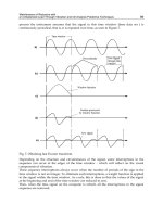
This kind of dissipater was first applied in the sky-jump spillway of Dongjiang Project in the early 1990s with the unit width discharge
flow reaching 600 m3 (s-m)−1. The prototype observations performed in 1992 (see Figure 2) show a good relationship between model
and prototype on jet flow and scour patterns although the discharged flow does not reach the design value [4].
This new technique has been widely applied to more than 10 projects in China and also included in the ‘Design Specification for
River-Bank Spillway’.
H (m)
∇217.00
200
Gate opening
∇194.00
100%
52%
150
0
40
80
120
160
Figure 2 Flow pattern of slit bucket in Dongjiang sky-jump spillway (upper one in the case of real operation, bottom one in the case of model test).
488
Design Concepts
.1°
57
1 + 589.214
In recent years, the slit bucket has been studied in three large spillway tunnels in China. They have common characteristics in
which dam height is about 300 m, discharge capacity of each tunnel is over 3500 m3 s−1, and discharge head is over 200 m. The
details of the tunnels are given in Table 1.
The spillway tunnel in Xiaowan Project is located on the left bank. Reducing the riverbed and bank erosion is one of the tasks
during the design as the river valley is very narrow and the rock on the right bank further downstream of the energy dissipation zone
is not strong enough to resist erosion.
Four types of flip buckets have been studied (see Figure 3) [5]. As the injection angle of flow in type (a) is too small, it results in jet flow
to close the right and erodes the right bank in the original design. A large backflow appears along the left bank with a maximum return
R4
0
52.251
10.718
(a)
52.251
10.718
10.718
1 + 589
(b)
52.251
3.20
1.25
9.9°
2.9°
8.6°
(c)
(d)
Figure 3 Four types of buckets in Xiaowan arch dams. (a) Tongue shape bucket. (b) Tilted bucket I. (c) Tilted bucket II. (d) Slit bucket. (Hmax = 292 m,
Q tunnel = 3535 m3 s−1).
489
Recent Achievements in Hydraulic Research in China
flow velocity of 14 m s−1. The maximum depth of scour pit is 15.6 m and close to the right bank. Another two types of flip buckets, type
(b) and (c), have been proposed and tested. The scours in riverbed have not been improved ideally. The scours are still close to the right
bank.
Type (d) slit bucket is finally adopted by the design through optimization. The direction of jet flow is adjusted and dispersed
along the river channel. The riverbed and bank erosion has been reduced greatly. The configurations of the final design are that (1)
the width of edge is reduced from 14.0 to 4.45 m with the contraction ratio of 0.3178. The axis of slit bucket is asymmetrical with the
tunnel axis. The left-side wall is 3.2 m from the axis of the central line and the right-side wall is 1.25 m from the central line. (2) Two
steps of contraction are selected on the right-side wall in which the first contraction is 27.251 m long with a contraction angle of
2.86° and the second contraction is 25.0 m long and a further contraction angle of 7.08° is applied. (3) One step of contraction on
the left-side wall is 25.0 m long with an angle of 8.64°.
The physical model tests with a scale of 1:45 show that flow surface is raised suddenly through the slit bucket, and flow is
dispersed longitudinally in the range of 200 m downstream of river reach slightly close to the left bank without a return flow
(Table 2). The maximum flow velocity along the right bank is less than 8 m s−1, which is reduced by 40% compared with the original
design, and the maximum scour depth is 8 m in the case of low downstream river level. In most cases, the flow velocities along both
banks are less than 5 m s−1, which reduce the protection work greatly. A slight scour is measured in the design and under check flood
operation modes because the water depth downstream is much larger.Similar physical model tests have been performed on the
Xiluodu 3# spillway tunnel and Jinping spillway tunnel. Expected results have been obtained which reduced the scours downstream
riverbed greatly. Figure 4 gives the scours on riverbed by Jinping spillway tunnel under the designed reservoir water level [6]. The
maximum scoured depth on the proposed plan is 6.3 m.
6.18.2.2
Flaring Pier Gate
This new type of energy dissipater, state of the art, is specially developed for Ankang Hydropower Project [7, 8]. The stilling basin of the
project is located on a curved river reach and the riverbed is with a low ability of anti-scourging. The other reason is that the
construction has been proceeding and the length of the stilling basin cannot be further lengthened. A new concept of energy
dissipation has been proposed for this project, that is, combining the flaring pier gates on surface spillway with stilling basin, to
make the flow out of pier gates contracted laterally and dispersed longitudinally, which changes a two-dimensional (2D) flow into a
3D flow and increases the energy dissipation ratio (see Figure 5). The strong 3D turbulent flow can create aeration in the flow through
lateral space. High ratio of energy dissipation makes the length of the stilling basin to be shortened and the construction work reduced.
This new energy dissipater was applied to the Ankong Hydropower Project in the middle 1970s with the maximum unit width
discharge flow of 254 m3 (s-m)−1. Finally, the length of the stilling basin is reduced by one-third. In fact, the Panjiakou surface spillway
is the first one that adopted this kind of energy dissipater in the world. Further inventions have been made by combining with bottom
outlets in Wuqiangxi and Baise Hydropower Projects, or RCC stepped spillway in Shuidong and Dachaoshan Hydropower Projects.
Dachaoshan Hydropower Project is an RCC gravity dam with a maximum height of 111 m and a unit width discharge flow of
193.6 m3 (s-m)−1. The energy dissipater is a flaring pier gate with stepped spillway, and the roll bucket is adopted in the downstream.
Special measure has been taken in the design that the first step is two times higher than normal ones, so that it will make the flow
project over several steps and a large cavity is formed under the jet flow; thus, more air enters the bottom of the flow. The hydraulic
field observation was carried out under normal water level in 2002 when the reservoir was filled for the first time. The observed results
[9] show that (1) the pressure variations on steps have been changed a lot, and the pulsation pressure is as high as 10 kPa (see Table 3);
and (2) the air concentration on steps is over 30%, which is much higher than the chute spillway. The analysis indicates that the first
high step plays an important role in cavitation mitigation on steps (see Figure 6). Slit bucket can also be applied to surface spillway to
reduce the scouring downstream. Guangzhao RCC Dam is a good example. The dam height in Guangzhao is 195.5 m with a
maximum discharge flow of 9857 m3 s−1. Three surface spillways and two bottom outlets are adopted in the design.
Traditional flip bucket is used in the beginning of the design. As a 30° bucket angle is taken in the middle one and 22° in the side
one, the elevation difference between the middle one and the side one is 2.75 m. The buckets on both sides are slightly contracted
from the width of 16 to 13 m.
Table 2
Scour depth and location by slit bucket in Xiaowan Project
Location of maximum depth of
scoured pit
(m)
Maximum scoured pit
(m)
No.
Operation mode
Reservoir water level
(m)
Downstream water level
(m)
Change
Distance from axis
Elevation
Depth
1
2
3
4
5
6
Start operation
Start operation
Start operation
P = 1%
Design flood
Check flood
1236.50
1236.50
1236.50
1236.90
1238.30
1242.51
998.92
1000.60
1002.69
1010.18
1012.73
1016.70
0 + 325
0 + 330
0 + 310
0 + 320
0 + 340
Not scoured
5 m to the right
5 m to the left
5 m to the left
0
5 m to the left
972.3
972.8
973.8
976.8
079.3
7.7
7.2
6.8
3.2
0.7
490
Design Concepts
(a)
1602
1606
1610
1614
1618
1622
1614
1618
22
16
1630
1610
2
162
22
16
1626
1626
2
162
1618
(b)
(c)
1618
1622
2
6
20
16
16
24
162
0
16
16
6
1630
161
161
161
1626
6
1614
161
1610
1628
1624
20
16
20
16
4
162
20
20
16
1616
16
1620
Figure 4 Scours by two types of buckets and flow pattern of slit bucket under the designed reservoir water level in Jinping spillway tunnel: (a) scour by
oblique bucket; (b) flow pattern of slit bucket; and (c) scour by slit buctet (model scale 1:30), (H = 278 m, Qtunnel = 3535 m3 s−1).
Recent Achievements in Hydraulic Research in China
(a)
A
491
B
(c)
A
(b)
B
(d)
Figure 5 3D energy dissipation by flaring pier gate. (a) Plan view, (b) side view, (c) section A–A, (d) section B–B.
Pressure and air concentration on steps in Dachaoshan Hydropower Project
Table 3
V (m s−1) on the height of 3 cm/
8 cm/15 cm
Air concentration
(C%)
Step no.
Pave/σ
(kPa)
Pmax/ Pmin
(kPa)
Case I
Case II
Case I
Case II
15#
21#
26#
30#
3.8/3.2
6.5/6.4
2.9/2.7
5.5/6.8
44.3/–3.3
62.0/–7.8
28.7/–10.2
78.8/–12.9
21.7/26.2/27.5
21.3/24.2/26.6
-/23.5/26.9
21.0/24.7/27.1
21.3/26.8/27.9
23.0/26.2/25.9
-/26.0/28.9
32.0
39.1
49.5
39.5
35.8
45.5
51.3
(a)
(b)
∇ 899.0
Flow surface line
on the wall
Flaring pier gate
Flow wing
Main jet flow zone
0 + 000
Cavity without
water
Energy dissipation zone
Air-water mixture
and air
Entrainment zone
0 + 120
0 + 100
Aeration from the sides
Figure 6 Flow pattern in Dachaoshan flaring pier gate with RCC stepped spillway: (a) schematic flow pattern and the concept of energy dissipation and
(b) operation in case I.
492
Design Concepts
The physical model tests show that (1) the overburden in the energy dissipation zone is almost scoured to the downstream with
a maximum scouring depth of 26 m, and solid rock on the riverbed is scoured by 5 m; (2) toes of side banks are also scoured; and
(3) the scoured materials are accumulated around the tailrace with a maximum height of 18–20 m, which will severely affect the
operation of power plant.
The proposed slit bucket [10] is designed with (1) bucket angle of –10° applied for all three with a contraction ratio of 0.3; and
(2) unsymmetrical contraction on side buckets and symmetrical contraction on the middle one with the width of edge of 4.8 m.
Figure 7 gives the comparison of scouring pattern by two types of flip buckets under the check flood operation mode. It indicates
less scouring by slit bucket.
6.18.2.3
Jet Flows Collision with Plunge Pool in High-Arch Dams
As some high-arch dams are constructed in narrow valleys, the collision of energy dissipation by jet flows of surface spillways and
middle outlets and a large plunge pool downstream is often chosen. The very successful project is the Ertan high-arch dam.
The design criteria on the slab of plunge pool are that the maximum impinging pressure must be less than 15 � 9.81 kPa.
Commendable efforts on the arrangements of the spillways, middle outlets, and plunge pool have been made and measured by the
physical models during the design stage, such as the impinging angle between surface spillway and middle outlet, the shape of flip
bucket of surface spillway, the length of plunge pool and the elevation of the floor considering the excavation, and the height of
secondary dam. The final solution on the arrangement of discharge facilities in Ertan Dam are seven surface spillways and six middle
outlets, and the length of plunge pool is 330 m with a 32 m high secondary dam (see Figure 8). Different flip buckets are adopted in
every opening of the surface spillway. The maximum discharge flow through the surface spillways and middle outlets is 16 300 m3 s−1
(a)
600
595
Rock
590
Overburden
Scoured line
EL. (m)
585
580
575
570
565
560
555
550
150
200
250
300
350
400
450
500
Station (m)
550
600
650
700
750
800
(b)
600
Rock
Overburden
Scoured line
595
590
585
EL. (m)
580
575
570
565
560
555
550
545
540
150
200
250
300
350
400
Station (m)
450
500
550
600
Figure 7 Comparison of scour pattern by two types of flip buckets under the check flood operation mode. (a) Scour in the original design, (b) scour in
the proposed slit bucket.
493
Recent Achievements in Hydraulic Research in China
(a)
Axis of dam
Max. H. W. EL.
Normal H. W. EL.
1203.5 1200.0
1188.5
Min. H. W. EL.
1155.0
Emergency gate of
middle level outlet
Original riverbed
1014.0
Max. impingement pressure (9.81∗kP)
50
45
40
Deep well pump house
Temporary bottom outlet
Prototype
Model test
35
1032.0
30
70
Plunge pool
965.0
120
170
220 m
980.0
Drainage holes
Bed rock surface
Grout curtain
(b)
1205.0
Drainage curtain
Figure 8 Design of discharge structures and plunge pool in Ertan Project: (a) general design of energy discharge structures and (b) comparison between
the prototype measurements and model tests in Ertan plunge pool.
(68.2% of total discharge) and the critical situation is the independent operation of surface spillway with the maximum impingent
pressure of 14.0 � 9.81 kPa under the check flood reservoir water level.
The Ertan Arch Dam was completed in 1999 and hydraulic field observation was carried out in the same year. The field
observation results are in good agreement with the model’s results [11], shown in Figure 8. The field observations are carried out
under the design reservoir water level with a discharge flow of 8000 m3 s−1 (four surface spillways and four middle outlets).
The design concept of energy dissipater in Ertan Dam is accepted by other high-arch dams, such as Jinping (305 m), Xiaowan
(292 m), Xiluodu (278 m), Baihetan (277 m), Goupitan (232 m), and Laxiwa (250 m), which all have large plunge pools with a
length of about 400 m and secondary dams with a height of about 40 m.
As the pressures on the vertical wall of the differential buckets in Ertan are quite low, even negative, the differential flip
buckets between surface spillways are recommended and studied on Xiaowan, Goupitan, Xiluodu, and Baihetan arch dams. The
angles of buckets change from –35° to 10°, which makes the jet flows separated along the plunging pool and the impinging
pressures reduced greatly. For example, the maximum discharge flow through seven surface spillways and eight middle outlets
in Xiluodu Project has increased from 30 000 to 33 800 m3 s−1 with the bucket angles of surface spillways from –30° to 10° and
the maximum impinging pressure being controlled under 13.0 � 9.81 kPa. The angles in Xiaowan Arch Dam are from –20° to
10° and in the Baihetan from –35° to 20°; the maximum discharge flow can be increased by about 10%. The bucket shape is
also an important factor to spread the flow to lateral directions and reduce the impinging pressure. Figure 9 gives the flow
Figure 9 Flow pattern by surface spillways of Baihetan Arch Dam.
494
Design Concepts
pattern through surface spillway in Baihetan Arch Dam from the physical model [12]. The surface spillways and middle outlets
are all optimized.
6.18.2.4
Orifice Spillway Tunnel
Figure 10 Pressure and hydrophone sensors arrangement in Xiaolangdi 2# orifice tunnel.
Cp
24
18
16
14
12
10
100
150
Figure 11 Pressure coefficients of 2# orifice tunnel in Xiaolangdi Project.
3# orifice plate
Observed
2# orifice plate
Model
20
1# orifice plate
22
200
250
(m)
0 + 265.93
0 + 236.68
0 + 243.93
AP42−4
ZD42−1PF42−6 PF42−7
0 + 200.43
0 + 164.18
0 + 156.93
0 + 149.68
0 + 127.93
0 + 120.68
0 + 113.43
0 + 106.18
AP42−3 PF42−5 HP42−3 HP42−4
PF42−4
0 + 214.93
PF42−3 HP42−2
0 + 207.68
AP42−2
PF42−2
0 + 193.18
PF42−1 HF42−1
0 + 171.44
AP42−1
D14.50
The principle of energy dissipation of orifice spillway tunnel is sudden contraction and then sudden expansion through
the orifices. It was first applied in the Mica Dam in the 1980s but the discharge capacity was less than 1000 m3 s−1. The
first large-scale orifice spillway tunnel was adopted in Xiaolangdi Project by reconstruction of diversion tunnel in the
1990s.
Xiaolangdi Project has a rockfill dam with a maximum height of 154 m and a total discharge capacity of 17 063 m3 s−1. All
discharge structures are located on the left bank, including one chute spillway, three spillway tunnels, three orifice tunnels, and three
silt flushing tunnels. The powerhouse is also located on the left bank. The main consideration on the orifice spillway tunnel is
cavitation. The objectives of studies include optimization of the number, interval, orifice plate shape, adoption of abrasion-resistant
concrete, and inclined ratio on the top of the chamber to increase the pressure of the tunnel. The final design of the orifice tunnel is
that three orifice plates are installed in the horizontal pressurized tunnel with an interval of 3D (D is the diameter of the tunnel,
D = 14.5 m). The contract ratios of these are 0.690, 0.724, and 0.724, respectively, which result in a strong rotation, shear and
turbulent flow, dramatic energy dissipation, and reduction in velocity to about 10 m s−1 (see Figure 10). More details of the research
had been considered during the design, including the different scales of conventional model tests, depressurized model tests, and
intermediate prototype observation in the Baozhusi silt tunnel.
The orifice spillway tunnel was first operated in April 2000 and hydraulic field observations have been carried out with the working
heads of 70 and 100 m on 1# tunnel and 100 m on 2# tunnel [13, 14]. The parameters observed are pressure and flow noise in the
pressurized tunnel; pressure, cavitation noise, air entrainment, and air concentration in the open flow tunnel; and strength and stress on the
radial gate.
The model test results and field observations show that they are in consistency with the energy dissipation ratio and pressure
distribution (see Figure 11). A slight cavitation noise is still observed at the gate opening ratio from 0.96 to 0.99 (see Figure 12).
Sound increment of spectrum level at 11.6 to 27.0 dB in a high-frequency band is observed. But no cavitation damage is found
during inspection after several rounds of operation.
The scale effect on cavitation has been a cause for concern during the design. Several physical model experiments, under the
normal atmosphere condition and depressurized condition, are carried out with the model scale of 1:40 to 1:30 [15]. An
intermediate test on the silt flushing tunnel in Pikou Project was performed for further analysis of scale effect. Table 4 shows that
Recent Achievements in Hydraulic Research in China
Autospectrum (HP42−4) - Input
Working : Input : Multi-buffer 1 : CPB analyzer
495
[dB/20. 0u Pa]
160
140
120
100
400
200
63
250
1k
(Hz)
4k
16k
63k 0
(s) (Nominal values)
Figure 12 Spectrum of flow noise downstream of the third orifice plate during the gate opening.
Table 4
Flow cavitation numbers of three orifice plates at the
full gate opening (σ)
Model test
Water head (m)
1st orifice plate
2nd orifice plate
3rd orifice plate
130.0
5.23
5.04
4.40
Observation
105.0
5.18
5.01
4.41
85.0
5.19
5.04
4.42
103.0
5.29
5.14
4.37
the flow cavitation numbers based on the observed data under the working head of 103 m are very close to the ones calculated based
on the physical model test results under the working head of 105 m. It indicates that the previous studies and methods are able to
predict the cavitation characteristics of orifice tunnel at the design working head – the flow cavitation intensity at the full reservoir
water level will be greatly changed.
6.18.2.5
Vortex Shaft Spillway Tunnel
Rebuilding the diversion tunnel into the spillway tunnel is another way to reuse the diversion tunnel. It can also solve the difficulty
in the arrangement of connection tunnel by flexible arrangement of the intake. The vortex spillway tunnel is one way to reuse the
diversion tunnel. There are two types of vortex shaft spillway tunnels: one is vertical and the other is horizontal, both making the
flow run in rotation to dissipate the energy.
Shapai Project is the first one to adopt a vertical vortex shaft spillway tunnel in China which is reconstructed from diversion
tunnel [1]. The discharge capacity is about 250 m3 s−1 with a head of 100 m. The first operation began just after the ‘5-12’ Wenchuan
earthquake in 2008 in China to control reservoir water level from overtopping.
The hydraulic studies on large-scale vortex shaft spillway tunnel are much more challenging and have been carried out in
Xiluodu and Gongboxia Projects.
The Xiluodu Hydropower Project has an arch dam with a maximum height of 278 m and a maximum discharge flow of about
50 000 m3 s−1. There are four large spillway tunnels with a maximum discharge flow of about 4000 m3 s−1 each. The vertical vortex
shaft spillway tunnel is an alternative to discharge the extra flood; otherwise, an additional long tunnel must be built. The design is a
conventional intake with a head of 60 m and a short connecting tunnel of about 100 m long, a one-fourth of elliptical curve at the
end of the horizontal tunnel connecting to a chamber with a diameter of 22 m, and a vertical shaft with a diameter of 16 m
connecting to the original diversion tunnel. As the energy dissipation head is about 220 m and the maximum discharge flow is
2700 m3 s−1, the cavitation must be carefully considered. To increase the wall pressure especially on the lower part of the shaft and to
increase the flow cavitation number, an orifice plate on the lower part of the shaft can be considered and it is effective. A plunge pool
in the diversion tunnel is used as it is easy to be built and has the same function as the orifice. The energy dissipation ratio of such
arrangement can reach up to 85% [16] (see Figure 13).
496
Design Concepts
Figure 13 Xiluodu vortex shaft spillway tunnel model.
The horizontal vortex spillway tunnel is studied for the Gongboxia Hydropower Project [17]. The original spillway tunnel
is rebuilt by a diversion tunnel in a conventional way with an inclined tunnel. During the excavation of the intake, it is found
that the geological condition is not favorable, and hence another solution must be considered. By analysis and comparison, a
horizontal vortex spillway tunnel is selected. The discharge head is 100 m and the maximum discharge flow is 1100 m3 s−1.
The diameter of the vertical shaft is 9 m and a one-fourth of elliptical curve is connected to the diversion tunnel. The diameter
of the horizontal vortex tunnel is 11 m and it is 50 m long (see Figure 14). A 40 m long plunge pool and a special energy
dissipater are adopted for energy dissipation. A physical model with a scale of 1:40 is built for pressure, velocity, and aeration
measurements. As the vertical shaft is a pressurized flow, a circular orifice plate is adopted for air entrainment and cavitation
mitigation.
The real operation of the horizontal vortex tunnel and field observation was carried out in August 2006. The reservoir
water level during the observation was close to the normal water level, which means that the discharge water head and
capacity were about 104 m and 1130 m3 s−1, respectively. The main parameters observed are water levels in reservoir and
river channel downstream, pressure distribution, flow pattern in the horizontal tunnel, airflow and its velocity distribution
in the air vent, air concentration, structure vibration, and structure dynamic response such as displacement, stress, and
strain [18].
497
Recent Achievements in Hydraulic Research in China
C
B
Detail A
Detail B
2010.00
C
L
A
1989.00
Vent pipes
1965.60
5−φ0.63
Weir
20°
1.3
0.8
R4.5
Shaft
Flip bucket R2.8
X2
25
5.
1933.385
y
1915.385 O
Vent shaft
Aerator
See detail B
15.22
R
A
+
Y2
81
–1
1900.385
Vent shaft
X
1915.385
1905.635
1900.385
C
Stilling basin
B
Section B–B
0+321.22
B
Section C–C
Swirling flow tunnel
0+270.00
Swirling flow generator see detail A
0+361.22
A
0+220.00
D10.5
Shaft axes
3.5
Diversion tunnel
Inlet
B
C
ion
ers
Div
nel
tun
Concrete plug
Swirling flow tunnel
Stilling basin
Section A–A
Figure 14 Design of horizontal vortex shaft spillway tunnel in Gongboxia.
The main observed results are (1) the air vent works well after the gate opening and the maximum airflow velocity is about
120 m s−1 with a maximum airflow of 403.4 m3 s−1, which is about 36% of the flow rate in the spillway tunnel. The cavity length
downstream of the aerator is about 17 m, which is about 3 times the model result. The near-wall air concentration in the shaft is
more than 8%, which is much higher than the one obtained on the floor from the other projects. Enough airflow is not only good
for cavitation mitigation, but it can also increase the energy dissipation ratio. (2) The pressure distribution has a good agreement
with the model tests. (3) The energy dissipation ratio is up to 84.5% and the velocity in the horizontal part of the tunnel is less than
15 m s−1. (4) Flow is very smooth during the gate opening and closing as well as the full opening operations observed by a video
camera installed in the crown of the tunnel. (5) The dynamic responses of the structure are all under the design conditions. All
measured results have been applied to the safety assessment of the project and provided useful information for further research and
design of similar vortex shaft spillway tunnels.
The diameters of the vortex chamber and shaft, connection tunnel and elliptical curve, energy dissipater, and aerator can be
determined from the research on Shapai, Xiluodu, and Gongboxia vortex shaft spillway tunnels.
6.18.3 Aeration and Cavitation Mitigation Measures
The main characteristics of Chinese dams are high head and large discharge flow. Therefore cavitation damage must be
paid much more attention. Since the first aerator was successfully applied in the Fengjiashan spillway tunnel in 1979,
much more studies have been carried out on hydraulic characteristics. Systematic studies on the aeration and cavitation
mitigation measures have been carried out [19, 20] and have been accepted by the Design Code of Spillway, such as the
determination of offsets and offset combined with ramp, and calculation of length of cavity, airflow, pressure in cavity, air
concentration in cavity, and protection length. Design Code of Spillway indicates that (1) the aerator must be adopted
with a velocity over 35 m s−1, (2) the air concentration along the floor should be more than 4–5% to mitigate the
cavitation damage, and (3) the length between two aerators has to be about 120–150 m. The studies also show that the
negative pressure downstream of offset should be kept around –10 kPa. As the physical model test results are usually
498
Design Concepts
smaller than prototypes by the scale effect of similarity, further studies should be conducted on the proper prediction
from the physical test results.
The offset, which is perpendicular to the spillway floor, combined with a small ramp is commonly applied. The height of
the offset is about 1 m and it depends on the discharge flow and the slope of the chute. The vertical offset combined with the
lateral offset is also considered by the reason of a round water stop arranged in the case of high-head radial gate while the
water head is as high as 60–70 m. The ramp is not recommended when the aerator is placed on the steep inclined part of
the spillway tunnel because the flow could be projected to the ceilings of the tunnel, which might cause a temporary
pressurized flow.
The critical point of cavitation protection in the spillway tunnel is the end of inversed part after the inclined tunnel
where the tunnel is changed to be horizontal and the pressure along the floor is changed dramatically. Several projects
have incurred serious damages downstream from this point. A differential type of aerator is specially studied for the
Ertan spillway tunnel when the Froude number, which makes a good aeration on the floor (see Figure 15), is not big
enough.
The water head between the reservoir and the end of the inversed tunnel in Ertan 1# spillway tunnel is 102 m and the discharge
capacity is 3700 m3 s−1, which results in high-speed flow and aeration. Therefore the measure of cavitation mitigation should be of
more concern. The recent model tests show that the air concentration by different aerators is not appreciated for the side wall, and
the air concentration is nearly zero. Therefore, a 3D aerator for both bottom and lateral aeration is proposed and systematic studies
have been carried out [21]. Figure 16(a) shows the details of its configuration. The minimum air concentration on the side wall is
larger than 1%. The field observation between the second and third aerators in Ertan 1# spillway tunnel is performed after the
rebuilding of the aerators [22]. Much air is entrained through the air vents with the air concentration in the air cavity over 83%. The
minimum measured air concentration on the farthest point, about 200 m from the second aerator, is 4.2% after the 3D aerator is
applied but the previously observed minimum air concentration on the same point was only 2.8%. The higher the air concentration
on the floor, the better the effect of cavitation mitigation. Inspection on the tunnel after 190 h of operation has not found any
cavitation damages.
(a)
(b)
R0.2
m
1
4.98% d2
b1
R0.2
7.9%
R0.2
m
Detail A
4.3
Detail A
R 0.2
R 0.2
R 0.2
R0.2
d1
1.4
I
13.0
2.0
i = 0.079
1.12
6.0
n
6.0
R285.7
i = 0.079
1.12
3.0
0.5
1.4
R 0.2
0.5
5.7
Z
1−1
Vertical Cross Section diagram
Figure 15 Aerators in Ertan 1# spillway tunnel: (a) differential aerators and (b) modified 3D aerator.
(b)
(a)
Section 2−2
0.1
Section 1−1
1.10
i = 0.03
8.5
0.75
Drainage conduit
7.833
0.7
7.833
2
1
1:20
1:12
2
1
Diversion tunnel
Figure 16 Special aerators: (a) aerator in Longyangxia Project and (b) aerator in Zipingpu Project.
Aerator
10.7
1.8−75
10.7
i = 0.03
Recent Achievements in Hydraulic Research in China
499
Some special types of aerators or ramps (see Figure 16(b)) are applied when the tunnel slope is too small and special
configurations have been determined; for example, the combination of upstream and downstream ramps and groove is applied
to the spillway tunnel in Longyangxia [1]. A circular ramp is applied to the Zipingpu tunnel spillway [23].
The research has found that the conventional step of offset is not satisfied in a large slope of tunnel; for example, the slope
in Xiaowan spillway tunnel is over 10%, as insufficient air is trapped and air cavity is sometimes filled by water.
A two-step aerator has been developed based on the physical model experiments [5] (see Figure 17). Type (a) is used only in the
first aerator and type (b) is used for the remaining six aerators. H1 and L1 in the second aerator are larger than the others as it is
located at the end of the inversed part of the inclined tunnel. Air concentration on each aerator is satisfied (see Figure 18).
6.18.4 Flow-Induced Vibration
In recent years, special attention has been paid to the problem of high-velocity-flow-induced vibration because lots of large dams are
constructed in China. Vibration problems often arise at hydraulic gates, trash racks, pipes, and dams of discharging flow.
The mechanism of vibration is very diverse and complex. Two general types of flow-induced vibration may be distinguished:
(1) extraneously induced vibration, such as turbulence vortex-excited vibration; and (2) instability-induced vibration, caused by
flow instability or movement instability.
According to the research of some engineering examples, the vibration problem of sluice structure can be forecasted or limited in
two ways. (1) During the design stage, the physical or mathematical model should be used to predict the dynamic response for the
hydraulic structure in complex flow situation, such as high-head and large dimension gates, and high-discharging arch dams. Great
progress has been made in the mathematical simulation of fluid and dam, sluice gate structure coupling vibration by using a finite
element method. There is a mature experience in the physical modeling of flow and concrete structure coupling vibration by using
tailor-made latex. During the past 10 years, many efforts have been made in developing a special hydraulic-elastic material for the
modeling of fluid-induced steel structure vibration, and now it is also becoming a mature modeling technique which is widely used
in the flow-induced gate vibration research. (2) During the operation stage, the prototype research should be done to evaluate the
degree of vibration or to avoid harmful vibration. Field observations are also used to verify whether the projects or gates are in safe
operation conditions or to calibrate the research. Many observations of large-sized radial gates of surface spillways and some radial
gates with high heads have been carried out by research engineers (see Figures 19 and 20).
6.18.5 Discharge Spraying by Jet Flow
The impinging of jet flows or free flows may create spraying rainfall especially in the case of high dam operation with
large discharge flow that may damage some structures. This causes the switch yard to break down in the initial operations
(a)
i = 10.5578%
i = 1:1
0
i = 10.5578%
1.3
0
0
H1
0
(b)
0.5
1:1
i = 20
.7772
2.78
1.5
0
L1
%
i = 10.5578%
L2
Figure 17 Two steps of offset for Xiaowan spillway tunnel: (a) one step of offset in the original design and (b) two steps of offset after modification.
Air concentration (%)
5
Check
Design
Start operation
4
3
2
1
0
62
64
66
68
70
72
74
76 (m)
Figure 18 Air concentration measurement between the second and third aerators along the floor at different water levels.
500
Design Concepts
Figure 19 Gate vibration test of bottom outlet in Xiaowan Hydropower Project.
Figure 20 Prototype research of gate vibration in Xiaolangdi Project.
Flow splashing zone Raining zone
Spray flying zone
Nappe
Figure 21 Mechanism of discharging spray.
in Liujiaxia and Xin’anjiang Hydropower Projects, blocks the access to the powerhouse in Dongfeng Hydropower Project,
and brings about landslides in Lijiaxia Hydropower Project. The discharging spraying appeared since the 1970s and a wide
range of research has been carried out in China mainly through model tests, numerical simulations, and field
observations.
As there is a large-scale effect between the physical model test and prototype, and the numerical model is very difficult to
be verified, the field measurement on the spraying intensity is quite reasonable. The measurement technique was first applied
to Dongjiang Project in 1992. The project is a 157 m high-arch dam built in a very narrow valley. Two spillways were built on
the right embankment and one on the left. The total discharge capacity is 5610 m3 s−1. For the purpose of spraying intensity
measurement, a special digital rain gauge is developed and the data are acquired by an SG20 hydraulic parameter system
controlled by computer. Figure 21 shows the mechanism of discharging spray that the flow splashes and becomes a main
source of spraying and makes a very strong and intensive rainfall. The rainfall distributions and the effects have been analyzed.
Recent Achievements in Hydraulic Research in China
501
The designers of the later projects have learnt much more about discharging spray and make a proper arrangement of the
structures and bank protections. There are several other projects that have been measured in the same way, such as Lijiaxia for
the purpose of making proper protection on both banks, and Manwan and Dachaoshan Projects for the purpose of making
proper design of access gallery to the powerhouse [1, 24].
A field observation of discharging spray was carried out in Ertan Project in the case of surface spillway operation, middle outlet
operation and their combinations, and spillway tunnel operations when the project was first put into operation in 1998 and 1999
(see Figures 22 and 23 and Table 5).
Some results have been achieved. (1) There are high spray intensities on the two banks in the case of I–III under the
elevation of 1115 m. (2) The spray intensity in case III is higher than that in case I or II. This shows that the collision by surface
Figure 22 Intensity distribution of discharge spray by four surface spillway and four middle outlets in Ertan Project in 1999.
Figure 23 Discharge in Ertan Project in 1999.
502
Table 5
Design Concepts
Main cases and the results of spray measurement in Ertan Project
Spray intensity
(mm h−1)
Case
Gate openings
I
II
III
6 middle outlets
7 surface spillways
4 surface spillways + 4 middle outlets
(1, 2, 6, 7 surface spillways and 1, 2, 5, 6 middle
outlets)
1# and 2# spillway tunnels
IV
Reservoir
level
(m)
Discharge
(m3 s−1)
2# tailrace
platform
Left
bank
Right
bank
1199.69
1199.71
1199.33
6856
6024
7757
7.1
1.8
104
833
850
1180
491
305
750
1199.78
7378
1000
422
spillways and middle outlets would cause much stronger spray intensity than one by surface spillways or middle outlets
although such type of discharge arrangement could have a high efficiency of energy dissipation. (3) There is a strong spray close
to the 2# tailrace platform, which indicates that it could be very difficult to have access to the gallery for checking the plunge
pool during the discharging [11].
The spray rainfall intensity in Ertan Project is very valuable to the further understanding of the mechanism of discharging spray
of high dams. The research based on this measurement and other several field observations make a prediction for new projects. The
main parameters of influence range L and ξ are determined by Rayleigh method analysis [25]. The experimental formulas are
brought up to estimate the influence range and the rainfall distribution of spray in the practice. This method has been used to
predict spraying rainfall distribution in Xiaowan Project and allows the designer to make a proper protection especially on the right
bank downstream of the tunnel spillway.
6.18.6 Hydraulic Field Observations
Hydraulic field observation is a valuable tool to analyze and explain the scale effects and make a proper prediction according to
physical model studies. It is also one of the measures to evaluate the safety of the projects and the potential damages. More
than 80 field observations on hydraulics have been carried out in China during the past 50 years and techniques have been
developed especially on the instrumentations. The field observation on Foziling Dam was carried out on the flow pattern, the
pressures, and aeration on chute spillway in Moshikou in the early 1950s. The cavitation damage was measured in Xin’anjiang
in the 1960s.
The modern hydraulic field observations began from 1979 in Fengjiashan concentrating on air concentration as the aerator was
applied in China for the first time. Then many researches on the pressures and air concentrations were carried out for Wujingdu,
Dongjiang, Dongfeng, Ertan Projects, and so on. As there was some vibration on the radial gate in Liujiaxia, systematic studies
together with field observations were performed on the aspect of flow-induced vibration both for gates and dams. Many large and
high-head radial gates have been observed, such as the 19 � 26 m radial gate of surface spillway in Wuqiangxi in 1997 and the
13 � 13.5 m radial gate of spillway tunnel in Ertan. Similar to the discharge spray field measurement performed in Dongjiang Arch
Dam in 1992, studies on Dongfeng, Manwan, Lijiaxia, Dachaoshan, and Ertan have been done for different purposes. The
mechanism of cavitation damage is studied together with the field observations in many projects. Some relative parameters are
also measured at the same time, such as the pressures, air concentrations, and airflow rate. More than 15 parameters have been
measured up to now.
The comprehensive hydraulic field observations have been carried out in Ertan Project and ship lock of Three Gorges Project.
The observations in Ertan include plunge pool, surface spillways, spillway tunnels, middle outlet gate and spillway tunnel gate,
dam vibrations, and discharge sprays. Figure 24 gives a flow chart of hydraulic field measurement method and data acquisition
system which integrates advanced modern techniques, such as computer control, instrumentation, and diagnosing and
processing [26]. This technique has been widely applied to large hydraulic structure observations. The measurement results
contribute a great deal to the improvement of the design of hydraulic structures, such as large plunge pool, spillway tunnel, and
bank protection on discharging spray, which are also important data for the evaluation of safety of hydraulic structures, mainly
introduced in sections above.
The five-stage ship lock in Three Gorges Project is the largest one in the world. Many concerns have been concentrated on
the filling and emptying systems, such as the pressures and cavitation behaviors in valve chamber and diversion systems,
aeration and airflow during the valve opening, vibrations of valves and lock gates, stress on the lift poles of valve and AB
connect pole, operation of valves, wave in the lock chamber and in the channel during the gate opening and closing, and
Recent Achievements in Hydraulic Research in China
18 pulsation
pressure
sensors
18 average pressure
sensors
Laptop
computer
+ DJ800 data
processing
2 air speed
sensors
Surface
spillway
1. Two banks along plunge pool
2. Downstream of 1# tunnel
3. Downstream of 2# tunnel
18 pulsation
and 2 negative
sensors
5 air speed
sensors
848 types of air
concentration
sensors
by 6 channels
5 CQ-2 resistance
air concentration
sensors
Cameras, video
Plunge
pool
17 time-average
pressure sensors
20 rainfall
gauges
60 channels
of SG200 data
acquisition
503
Bottom
velocity
2#
spillway
tunnel
Flow pattern, jet trajectories
Discharging rainfall affection
Scouring by discharging
Hydraulic observations
Modal
DASP
modular
processing
Charge
amplifier
Force hammer
+ 12.5 t force
sensor
Charge
amplifier
Acceleration
sensor
Data logging
170 strain
sensors
YE5854
charge
amplifiers
8302(4)
accelerator
sensors
6M82
dynamic
strain
meter
170 strain
gauges
DLF-6 type
6-channel
amplifier
891II
acceleration and
displacement
sensors
Static force
Laptop
computer +
data
processing
CRAS
data
Dynamic force
INN303
data
processing
INN303 +
DASP data
processing
Flow-induced vibration observation
1.
Middle
outlet
gate
2. Gate
of 1#
spillway
1. Gate pier
of middle outlet
2. Dam
3. Power
intake tower
4. Auxiliary
powerhouse
Figure 24 Flow chart of hydraulic field measurement method and data acquisition system.
tensile stress of ship rope during filling and emptying. The measurements of the valve and filling systems on try-operation
were carried out in late 2002 with 10 cases [27]. The measurements on ship-lock operation were carried out in the summer of
2003. The measured results prove that the hydraulic behaviors of filling and emptying system are satisfied and the ship lock is
in good operation and has achieved the design requirements. Adjustment on valve operation mode reduces the time of filling
and emptying and increases the efficiency of ship transportation. Figure 25 gives a measuring arrangement in filling system
and Figure 26 gives some measured results.
504
Design Concepts
Hydrophone
B
A
Pressure
E
D
C
G
H
F
F20
KZ07
F10
F11
F18
F19
F12
F13
KZ11
F22
A
B
KZ09
F21
F14
KZ08
F15
F17
KZ10
KZ12
F23
C
F16
F24
E
D
F
H
G
Figure 25 Measurement arrangement in the filling and emptying system in the ship lock of Three Gorges Project.
(a)
(b)
P (kPa)
400
dB
100
350
1
0.8
60 kHz
60
250
80 kHz
100 kHz
80
300
0.6
200
40
0.4
150
20
0.2
100
MPa
(c)
0
200
400
600
t (s)
800
0
100
200
300
(s)
0
400
(d)
10.0
5.0
4
0.0
2
–5.0
Gate opening
0
–10.0
–15.0
–2
–20.0
–4
–25.0
0.0
0
100.0
200.0
300.0
400.0
500.0
–6
0
20
40
60
80
100
120
140
160
180
200
Figure 26 Measurement results in the ship lock of Three Gorges Project: (a) pressure vs. time in T pipe; (b) flow noises in valve chamber; (c) stress in A
pole of gate; and (d) acceleration speed of valve.
References
[1]
[2]
[3]
[4]
[5]
[6]
[7]
[8]
[9]
[10]
[11]
[12]
[13]
Pan JZ and He J (2000) The Fifty Years of Chinese Dams. China: China HydroPower Publication.
Semenkov VM (1979) Large-capacity outlet and Spillways, G.R.50. Proceedings of IV. 13th ICOLD, Paris. pp. 1–110.
Gao JZ and Li GF (1983) Studies on the application of Slit Bucket energy dissipators. Journal of Water Resources and Hydropower Engineering 14(3): 1983.
Tong XW, Li GF, Xie SZ, et al. (2000) The Contracted Types of Energy Dissipaters with High Water Head and Large Discharge Flow. China: China Agriculture Publication.
Sun SK, et al. (2006) Energy dissipation research of spillway tunnel by physical model (scale 1:45) on Xiaowan Project (in Chinese). HY-2006-3-27. China: China Institute of
Water Resources and Hydropower Research (IWHR).
Zhang D, et al. (2008) Energy dissipation research of Spillway tunnel by physical model (scale 1:30) on Jinping I Project (in Chinese). HY-2008-065. China: China Institute of
Water Resources and Hydropower Research (IWHR).
Lin BN and Gong ZY (2001) Contracted and flaring pier gates energy dissipaters (in Chinese). Proceedings of Lin Binnan’s Works. China: China HydroPower Publication.
Xie SZ and Lin BN (1992) Mechanism of energy dissipation by flaring pier gates and its hydraulic calculations (in Chinese). Journal of Water Power Volume 1.
Guo J and Liu ZP (2003) Field observations on the RCC stepped spillways with the flaring pier gate on the Dachaoshan Project. Proceedings of the IAHR XXX International
Congress. Theme D, pp. 473–478. August 2003.
Sun SK, et al. (2005) Energy dissipation research of surface spillway by physical model on Guangzhao Project (in Chinese). HY-2005-3-12. China: China Institute of Water
Resources and Hydropower Research (IWHR).
Gao JZ and Liu ZP (2001) Prototype observation of hydraulic and flow-induced vibration for Ertan Project. Proceedings of the Special Seminar, IAHR XXIX Congress. Beijing,
China, 2001.
Sun SK, et al. (2006) Energy dissipation research of surface spillways and middle outlets by physical model on Baihetan Project (in Chinese). HY-2006-3-55. China: China
Institute of Water Resources and Hydropower Research (IWHR).
Guo J and Liu JG (2001) Pressure observation for the 1# Orifice tunnel in Xiaolangdi Project. Proceedings of the Special Seminar, IAHR XXIX Congress. Theme D, pp. 663–668,
September 16–21, Beijing, China.
Recent Achievements in Hydraulic Research in China
505
[14] Wu YH, Guo J, Zhang D, and Liu JG (2004) The Prototype Observation of Hydraulic and Flow-Induced Vibration on Xiaolangdi 2# Orifice Tunnel. China: China Institute of Water
Resources and Hydropower Research (IWHR).
[15] Li ZY (1997) The hydraulic research on orifice tunnel (in Chinese). Journal of Hydraulic Engineering Volume 2.
[16] Dong XL and Guo J (2000) The study on a vortex shaft spillway tunnel with high water head and large discharge flow (in Chinese). Journal of Hydraulic Engineering 11: 27–33.
[17] Dong XL and Guo J (2003) The characteristics and operation reliability analysis on vortex spillway tunnels (in Chinese). Journal of Water Power 29(4): 33–35.
[18] Chen WX, Liu JG, Guo J, et al. (2007) Prototype observation of shaft horizontal vortex spillway of Gongboxia Hydropower Project. Proceedings of the IAHR XXXII Congress.
Venice, Italy. pp. 529–536.
[19] Shi QS, et al. (1983) Hydraulic experimental studies on aeration mitigation (in Chinese). Journal of Hydraulic Engineering, volume 3.
[20] Pan SB and Shao YY (1999) Design and Application of Aeration (in Chinese), Special Thesis on the Design Code of Spillway, edited by China South Design Institute. China:
China Water Resources and Hydropower Publication.
[21] Zhang D and Liu ZP (2005) Research on 3D aeration infrastructure shape of high-head, large-discharge spillway tunnel. Proceedings of the IAHR XXX1 Congress. Theme D,
September 11–16, Seoul, Korea.
[22] Zhang D, et al. (2006) Hydraulic Field Observation of 1# Spillway Tunnel on Ertan Project (in Chinese). China: China Institute of Water Resources and Hydropower Research
(IWHR).
[23] Chen WX, Li GF, Xie SZ, and Yang KL (2007) Study on aerators of high head spillway tunnels. Proceedings of the IAHR XXXII Congress. Theme D, July 1–6, Venice, Italy,
pp. 748–755.
[24] Guo J and Liu ZP (2005) Field study on the spray by discharging. Proceedings of the IAHR XXX1 Congress. Theme D, September 11–16, Seoul, Korea.
[25] Sun SK and Liu HT (2005) The rainfall distribution of atomized flow in large dams. Proceedings of the IAHR XXX1 Congress. Theme D, September 11–16, Seoul, Korea.
[26] Guo J (2000) Hydraulic prototype observations for Ertan Project. Proceedings of the ICOLD XX International Congress. Beijing, China. vol. 1, pp. 484–488.
[27] Liu JG and Wu YH (2004) The hydraulic field observation of the ship locks in three gorges project (in Chinese). Journal of China Three Gorges Construction (1): 17–22.