2012_Manual for Detailing Reinforced Concrete Structures to EC2_Jose Calavera
Bạn đang xem bản rút gọn của tài liệu. Xem và tải ngay bản đầy đủ của tài liệu tại đây (18.45 MB, 503 trang )
Manual for Detailing Reinforced
Concrete Structures to EC2
Detailing is an essential part of the design process. This thorough reference guide for the
design of reinforced concrete structures is largely based on Eurocode 2 (EC2), plus other
European design standards such as Eurocode 8 (EC8), where appropriate.
With its large format, double-page spread layout, this book systematically details 213 structural
elements. These have been carefully selected by Jose Calavera to cover relevant elements used
in practice. Each element is presented with a whole-page annotated model along with commentary and recommendations for the element concerned, as well as a summary of the appropriate
Eurocode legislation with reference to further standards and literature. The book also comes
with a CD-ROM containing AutoCAD files of all of the models, which can be directly developed
and adapted for specific designs.
Its accessible and practical format makes the book an ideal handbook for professional engineers working with reinforced concrete, as well as for students who are training to become
designers of concrete structures.
Jose Calavera is Honorary President of the Technical Institute of Materials and Construction
(INTEMAC- lnstituto Tecnico de Materiales y Construcciones) and Emeritus Professor, School
of Civil Engineering, Polytechnic University of Madrid.
Manual for Detailing Reinforced
Concrete Structures to EC2
Jose Calavera
W
~
Span Press
an imprint of Taylor & Francis
LONDON AND NEW YORK
First published 2012
by Spon Press
2 Park Square, Milton Park, Abingdon, Oxon OX14 4RN
Simultaneously published in the USA and Canada
by Spon Press
711 Third Avenue, New York, NY 10017
Spon Press is an imprint of the Taylor & Francis Group, an informa business
Copyright © 2012 Jose Calavera
The right of Jose Calavera to be identified as author of this work has been asserted by him in
accordance with sections 77 and 78 of the Copyright, Designs and Patents Act 1988.
All rights reserved. No part of this book may be reprinted or reproduced or utilised in any form or by
any electronic, mechanical, or other means, now known or hereafter invented, including photocopying
and recording, or in any information storage or retrieval system, without permission in writing from the
publishers.
This publication presents material of a broad scope and applicability. Despite stringent efforts by all
concerned in the publishing process, some typographical or editorial errors may occur, and readers are
encouraged to bring these to our attention where they represent errors of substance. The publisher and
author disclaim any liability, in whole or in part, arising from information contained in this publication.
The reader is urged to consult with an appropriate licensed professional prior to taking any action or
making any interpretation that is within the realm of a licensed professional practice.
Trademark notice: Product or corporate names may be trademarks or registered trademarks, and are
used only tor identification and explanation without intent to infringe.
British Library Cataloguing in Publication Data
A catalogue record tor this book is available from the British Library
Library of Congress Cataloging-in-Publication Data
Calavera Ruiz, Jose.
Manual tor detailing reinforced concrete structures to EC2 I Jose Calavera.
p.cm.
Includes bibliographical references and index.
1. Reinforced concrete construction-Details. 2. Reinforced concrete constructionStandards-Europe. I. Title.
T A683.28.C35 2012
624.1 '8341-dc22
2011009904
ISBN: 978-0-415-66348-9
Typeset in Helvetica by RefineCatch Ltd, Bungay, Suffolk
"
...,/-u'
~~~
MIX
Paper from
reeponelble sources
FSC- C004839
Printed and bound in Great Britain by the MPG Books Group
Contents
List of tables
Foreword
The author
Author's curriculum vitae
Acknowledgements
Citations
General notes
The three golden rules for pouring concrete on site
1 General rules for bending, placing, anchoring and welding
reinforcing bars
1. Introduction
1.1 Summary of codes and standards on construction details
1.1.1 Permissible mandrel diameters for bent bars (See EC2, 8.3)
1.1.2 Standard bends, hooks and loops
1.1.3 Cover
1.1.4 Bar spacing
1.1.5 Bundled bars
1.1.6 Surface reinforcement
1.2 Tying bars
1.2.1 Tying method
1.2.2 Tie points
1.3 Spacers and chairs
1.3.1 Types of spacer and chair
1.3.2 Graphic representation
1.3.3 Placement rules
1.4 Welding reinforcing bars
1.4.1 Types of weld
1.4.2 Welded joint details
1.5 Verification of the anchorage limit state
1.5.1 Bond anchorage
1.5.2 Welded transverse bar anchorage
1.6 Anchorage rules for welded transverse bars
1.6.1 Bars where 14 s
2 Constructive details
xiii
xv
xvii
xix
xxi
xxiii
xxv
xxvii
1
1
1
1
3
4
7
8
9
11
12
12
14
14
16
17
22
22
24
27
28
29
30
30
31
32
33
Group 01
Foundations
35
CD-01.01
CD-01.02
CD-01.03
Wall footing supporting a reinforced concrete wall
Wall footing supporting a brick wall
Spread footing
36
38
40
v
CD-01.04
CD-01.05
CD-01.06
CD-01.07
CD-01.08
CD-01.09
CD-01.10
CD - 01.11
CD-01.12
CD-01.12
CD-01.13
CD-01.14
CD-01.15
CD-01.16
CD-01.17
CD-01.18
CD-01.19
CD-01.19
CD-01.20
CD-01.20
CD-01.21
CD-01.21
CD-01.22
CD-01.23
CD-01.24
CD-01.25
CD-01.26
CD-01.27
CD-01.28
CD-01.29
CD-01.30
Spread footing with variable depth
Circular footing (Circular reinforcement)
Circular footing (Reinforced with two welded panels)
Spread footing and expansion joint
Strap footing
Self-centred edge footing
Combined edge footing (Variation 1)
Combined edge footing (Variation 2)
Strap footing at corner (1 of 2)
Strap footing at corner (2 of 2)
Self-centred corner footing
Combined footing (Variation 1)
Combined footing (Variation 2)
Tie beam between footings
Foundation beam (Variation 1)
Foundation beam (Variation 2)
Grid foundation (Variation 1) (1 of 2)
Grid foundation (Variation 1) (2 of 2)
Grid foundation (Variation 2) (1 of 2)
Grid foundation (Variation 2) (2 of 2)
Foundation slab (1 of 2)
Foundation slab (2 of 2)
Caisson
Wall footing
Bored pile
Pile cap
Two-pile cap
Three-pile cap
Four-pile cap
Group pile cap (N > 4)
Centring beam for one- or two-pile caps
42
44
46
48
50
52
54
56
58
60
62
64
66
68
70
72
74
76
78
80
82
84
86
88
90
92
94
96
98
100
102
Group 02
Retaining walls and basement walls
105
CD-02.01
CD-02.02
CD-02.03
CD-02.04
CD-02.05
CD-02.06
CD-02.07
CD-02.08
Cantilever retaining walls. Nomenclature
Cantilever retaining walls. Footing
Cantilever retaining walls. Stem
Cantilever retaining walls. Variations
Cantilever retaining walls. Key
Cantilever retaining walls. Construction joints in footings
Cantilever retaining walls. Vertical contraction joints in the stem
Cantilever retaining walls. Horizontal construction joints in
architectural concrete
Cantilever retaining walls. Vertical contraction joints
Cantilever retaining walls. Expansion joints
Cantilever retaining walls. Fill and drainage
Buttress walls. Buttress nomenclature and distribution
Buttress walls. Footing
Buttress walls. Stem
106
108
110
112
114
116
118
CD-02.09
CD-02.10
CD-02.11
CD-02.12
CD-02.13
CD-02.14
vi
120
122
124
126
128
130
132
CD-02.15
CD-02.16
CD-02.17
CD-02.18
CD-02.19
CD-02.20
CD-02.21
CD-02.22
CD-02.22
CD-02.23
CD-02.24
CD-02.25
CD-02.26
CD-02.27
CD-02.28
CD-02.29
CD-02.30
Buttress walls. Inside buttress
Buttress walls. End buttress
Tray walls
Tray walls. Tray details
Basement walls. Facade footing
Basement wall. Centred footing
Basement wall. Vertical contraction joint
Basement walls. Special details (1 of 2)
Basement walls. Special details (2 of 2)
Diaphragm walls. General reinforcement
Diaphragm walls. Crown beam
Diaphragm wall-beam bond (Variation 1)
Diaphragm wall-beam bond (Variation 2)
Diaphragm wall-beam bond (Variation 3)
Diaphragm wall-slab bond (Variation 1)
Diaphragm wall-slab bond (Variation 2)
Walls. Drainage chamber and channel in diaphragm wall
134
136
138
140
142
144
146
148
150
152
154
156
158
160
162
164
166
Group 03
Columns and joints
169
CD-03.01
CD-03.02
CD-03.03
CD-03.04
CD-03.05
CD-03.06
CD-03.07
CD-03.08
CD-03.09
CD-03.10
CD-03.11
CD-03.12
CD-03.13
CD-03.14
CD-03.15
CD-03.16
CD-03.17
CD-03.18
CD-03.19
Columns springing from the footing. Tie bar arrangement
Columns in intermediate storeys. Tie bar arrangement
Columns in top storey. Tie bar arrangement
Intermediate joint in edge columns (Variation 1)
Intermediate joint in edge columns (Variation 2)
Intermediate joint in edge columns (Variation 3)
Intermediate corner joint (Variation 1)
Intermediate corner joint (Variation 2)
Intermediate corner joint (Variation 3)
Facade or corner joint on last storey
Inside joint in intermediate storeys (Variation 1)
Inside joint in intermediate storeys (Variation 2)
Intermediate joint in circular columns
Transition from circular to rectangular columns
Corner joint in large span portal frames
Bar arrangement and shapes of ties in columns
Bundled bar arrangements
Arrangement of laps in columns with bundled bars
Edge schedule. Column schedule
170
172
174
176
178
180
182
184
186
188
190
192
194
196
198
200
202
204
206
Group 04
Walls subjected to axial loads
209
CD-04.01
CD-04.02
CD-04.03
CD-04.04
CD-04.05
Walls, shear walls
Walls, shear walls
Walls, shear walls
Walls, shear walls
Walls, shear walls
(Variation 1)
Walls, shear walls
(Variation 2)
210
212
214
216
CD-04.06
and
and
and
and
and
cores.
cores.
cores.
cores.
cores.
General arrangements
Joint detail
Corners, joints and edges
Detail of openings
Special details for slip forms
218
and cores. Special details for slip forms
220
vii
Group 05
Beams and lintels
223
CD-05.01
CD-05.02
CD-05.03
CD-05.04
CD-05.05
CD-05.06
CD-05.07
CD-05.08
CD-05.09
CD-05.09
CD-05.10
CD-05.11
CD-05.12
CD-05.13
CD-05.14
CD-05.15
CD-05.16
CD-05.17
Beams. Simply supported beams
Beams. Header joist
Beams. Continuous lintels with constant depth
Beams. Continuous lintels with variable depth
Beams. Staggered lintels
Beams. Stepped lintels
Beams. Edge soffit beam
Beams. Internal soffit beam
Beams. Soffit beam-edge beam intersection (1 of 2)
Beams. Soffit beam-edge beam intersection (2 of 2)
Beams. Transition from internal soffit beams to normal beams
Beams. Transition from edge soffit beams to normal beams
Beams. Joint details
Beams. Industrialised joint
Beams. Cantilevered beams
Beams. Arrangement of reinforcement at cross-section
Beams. Contraction joints
Beams with architectural concrete. Contraction joints and
construction joints
224
226
228
230
232
234
236
238
240
242
244
246
248
250
252
254
256
Group 06
CD-06.01
CD-06.02
CD-06.03
CD-06.04
CD-06.05
CD-06.06
CD-06.07
CD-06.08
CD-06.09
CD-06.10
CD-06.11
CD-06.12
CD-06.13
Slabs, ribbed slabs and precast slabs with beam-block
and hollow core floor systems
Slabs. General types: longitudinal and cross-sections
Solid slab. Connection to brick wall and concrete beams
Ribbed slab. Connection to brick wall and concrete beams
Slabs with self-supporting reinforced concrete joists.
Connections to brick wall
Slabs with self-supporting reinforced concrete joists.
Connections to reinforced concrete beams
Slabs with self-supporting reinforced concrete joists.
Connections to soffit beams
Slabs with self-supporting prestressed concrete joists.
Connections to brick wall
Slabs with self-supporting prestressed concrete joists.
Connections to reinforced concrete beams
Slabs with self-supporting prestressed concrete joists.
Connections to soffit beams
Slabs with semi-self-supporting reinforced concrete joists.
Connections to brick wall
Slabs with semi-self-supporting reinforced concrete joists.
Connections to concrete beams
Slabs with semi-self-supporting reinforced concrete joists.
Connections to soffit beams
Slabs with semi-self-supporting reinforced concrete lattice joists.
Connections to brick wall
viii
258
261
262
264
266
268
270
272
274
276
278
280
282
284
286
CD- 06.14
CD-06.23
CD-06.24
CD-06.25
CD-06.26
CD-06.27
CD-06.28
CD-06.29
CD-06.30
CD-06.31
Slabs with semi-self-supporting reinforced concrete lattice joists.
Connections to concrete beams
Slabs with semi-self-supporting reinforced concrete
lattice joists. Connections to soffit beams
Slabs with semi-self-supporting prestressed joists.
Connections to brick wall
Slabs with semi-self-supporting prestressed joists.
Connections to concrete beams
Slabs with semi-self-supporting prestressed joists.
Connections to soffit beams
Precast beam and block floor systems. Change in
beam direction
Precast beam and block floor systems. Connection
to wall parallel to beams
Precast beam and block floor systems. Cantilever with
extended joists
Precast beam and block floor systems. Cantilever without
extended joists
Beam and block floor systems. Openings
Slabs lightened with embedded tubing
Hollow cores. General details
Hollow cores. Connections
Hollow cores. Tip and edge tie hoops in cantilevers
Hollow cores. Vertical panel and beam supports
Hollow cores. Supports on vertical panels
Hollow cores. Supports on vertical panels and beams
Hollow cores. Openings in the slab
Group 07
Flat slabs
CD-07.01
CD-07.02
CD-07.03
CD-07.03
CD-07.04
CD-07.05
CD-07.05
CD-07.06
CD-07.06
CD-07.07
CD-07.07
CD-07.08
CD-07.08
CD-07.09
CD-07.10
CD-07.11
CD-07.12
CD-07.12
Flat slabs.
Flat slabs.
Flat slabs.
Flat slabs.
Flat slabs.
Flat slabs.
Flat slabs.
Flat slabs.
Flat slabs.
Flat slabs.
Flat slabs.
Flat slabs.
Flat slabs.
Flat slabs.
Flat slabs.
Flat slabs.
Flat slabs.
Flat slabs.
CD-06.15
CD-06.16
CD-06.17
CD-06.18
CD-06.19
CD-06.20
CD-06.21
CD-06.22
288
290
292
294
296
298
300
302
304
306
308
310
312
314
316
318
320
322
325
Top reinforcement
Bottom reinforcement
Arrangement of flexural reinforcement (1 of 2)
Arrangement of flexural reinforcement (2 of 2)
General details
Punching shear reinforcement (Variation 1) (1
Punching shear reinforcement (Variation 1) (2
Punching shear reinforcement (Variation 2) (1
Punching shear reinforcement (Variation 2) (2
Punching shear reinforcement (Variation 3) (1
Punching shear reinforcement (Variation 3) (2
Punching shear reinforcement (Variation 4) (1
Punching shear reinforcement (Variation 4) (2
Drop panels
Column with drop and head
Openings (Variation 1)
Openings (Variation 2) (1 of 2)
Openings (Variation 2) (2 of 2)
ix
of 2)
of 2)
of 2)
of 2)
of 2)
of 2)
of 2)
of 2)
326
328
330
332
334
336
338
340
342
344
346
348
350
352
354
356
358
360
Group 08
Stairs
363
CD-08.01
CD-08.02
CD-08.03
CD-08.04
CD-08.05
CD-08.05
Stairs. General layout details
Stairs. Reinforcement scheme for double flight
Stairs. Reinforcement arrangement for stairs with three flights
Stairs. Foundation for starting flight
Flying stairs (1 of 2)
Flying stairs (2 of 2)
364
366
368
370
372
374
Group 09
Bearings
377
CD-09.01
CD-09.02
CD-09.03
CD-09.04
CD-09.05
Bearings. Device for centring loads
Bearings. Confinement for linear loads
Bearings. Elastomer bearings
Flat jack housing to change bearings
Bearings. Plastic hinge
378
380
382
384
386
Group 10
Brackets and dapped-end beams
389
CD-10.01
CD-10.02
CD-10.03
CD-10.04
Brackets (Variation 1)
Brackets (Variation 2) (Suspended load)
Brackets. Double bracket
Dapped-end beams
390
392
394
396
Group 11
Ground slabs and galleries
399
CD-11.01
CD-11.02
CD-11.02
CD-11.03
CD-11-04
CD-11.05
CD-11.06
Ground slabs. Typical section
Ground slabs. Joints (1 of 2)
Ground slabs. Joints (2 of 2)
Ground slabs. Contraction joints
Ground slabs. Expansion joints
Ground slabs. Strengthening free edge of slab
Galleries. Ductways
400
402
404
406
408
410
412
Group 12
Chimneys, towers and cylindrical hollow columns
415
CD-12.01
Chimneys, towers and cylindrical hollow columns.
General layout
Chimneys, towers and cylindrical hollow columns.
arrangement of reinforcement
Chimneys, towers and cylindrical hollow columns.
Chimneys, towers and cylindrical hollow columns.
support lining
Chimneys, towers and cylindrical hollow columns.
Chimneys, towers and cylindrical hollow columns.
around the top
Chimneys, towers and cylindrical hollow columns.
foundations
Chimneys, towers and cylindrical hollow columns.
Chimneys, towers and cylindrical hollow columns.
water inflow pipes in submerged hollow columns
Chimneys, towers and cylindrical hollow columns.
CD-12.02
CD-12.03
CD-12.04
CD-12.05
CD-12.06
CD-12.07
CD-12.08
CD-12.09
CD-12.10
x
416
General
Crown details
Bracket to
Duct inlets
Circular slab
418
420
422
424
426
Circular slab
Annular footings
Plastic
428
430
432
Reinforcement laps 434
Group 13
Silos, caissons and rectangular hollow columns
437
CD -13.01
CD-13.02
438
CD-13.04
CD-13.05
CD-13.06
Silos, caissons and rectangular hollow columns.
Silos, caissons and rectangular hollow columns.
and connections (Horizontal sections) (1 of 2)
Silos, caissons and rectangular hollow columns.
connections (Horizontal sections) (2 of 2)
Silos, caissons and rectangular hollow columns.
pipes in submerged columns
Silos, caissons and rectangular hollow columns.
Silos, caissons and rectangular hollow columns.
Silos, caissons and rectangular hollow columns.
Group 14
Reservoirs, tanks and swimming pools
CD -14.01
Reservoirs, tanks and swimming
General details
Reservoirs, tanks and swimming
General details
Reservoirs, tanks and swimming
General details
Reservoirs, tanks and swimming
Reservoirs, tanks and swimming
Reservoirs, tanks and swimming
Reservoirs, tanks and swimming
joints in slabs on grade
Reservoirs, tanks and swimming
Reservoirs, tanks and swimming
construction joint watertightness
CD-13.02
CD-13.03
CD-14.02
CD-14.03
CD-14.04
CD-14.04
CD-14.05
CD-14.06
CD-14.07
CD-14.08
Silo sections
Intersections
440
Intersections and
442
Plastic water inflow
Hoppers
Foundations
Reinforcement laps
444
446
448
450
453
pools. Rectangular open tanks.
454
pools. Circular open tanks.
456
pools. Roofed reservoirs and tanks.
pools.
pools.
pools.
pools.
Corner details (1 of 2)
Intersection details (2 of 2)
Joints and bearings in walls
Contraction and expansion
pools. Joints in walls
pools. Specific details for improving
458
460
462
464
466
468
470
Group 15
Special construction details for earthquake zones
473
CD -15.01
CD-15.02
CD-15.03
CD-15.03
CD-15.04
CD-15.05
CD-15.06
CD-15.07
Summary of basic aspects
Geometrical constraints
Particular aspects of detailing (1 of 2)
Particular aspects of detailing (2 of 2)
Coupling elements in coupled walls
Reinforcement anchorage
Splicing of bars
Concrete foundations elements
474
476
478
480
482
484
486
488
491
493
References
Index
xi
List of tables
T-1.1
T-1.2
T-1.3
T-1.4
T-1.5
T-1.6
T-1.7
T-1.8
T-1.9
T-1.10
Minimum mandrel diameter to prevent damage to reinforcement (EC2)
Mandrel diameters for reinforcing bars in accordance with Table T-1.1
(B 400 or B 500 steel) (in mm) (EC2)
Minimum cover, cmm,
. b' bond-related requirements (EC2)
Recommended structural classification (EC2)
Values of minimum cover, cmin,dur' requirements with regard to durability
for reinforcement steel in accordance with EN 10080 (1) (EC2)
Maximum bundles general specifications
Bundles compressed bars in vertically cast members and overlap areas
in general
Bundles equivalent diameters in mm
Welding processes permitted and examples of application
Concrete. Indicative strength classes
xiii
2
3
5
6
6
8
9
9
23
32
Foreword
The aim of this book is to present a fairly full and systematic description of the construction
details used in concrete structures.
While I paid particular attention to construction details in my previous books, all dealing primarily with structural design and engineering, I was naturally unable to address the issue in depth
in any of them.
I have decided to do so today, acknowledging the importance of detailing and convinced that
it is one of the areas of expertise that professionals must quickly learn to master. Construction
details have a substantial impact not only on the quality of both the design and the building
processes, but on concrete structure maintenance and durability as well.
Forty-five to fifty per cent of the problems arising around concrete structures are widely known
to be attributable to the design stage. That half of those problems are due to errors in, or the
lack of, construction details is a fact much less generally recognised.
Detailing is always the outcome of a synthesis of four areas of knowledge:
•
•
•
•
a command of the theory underlying structural concrete engineering
on-site professional practice
experimental information obtained from laboratory trials
the experience obtained in forensic engineering studies.
The extraordinary complexity resulting from such diversity is deftly reflected in the expression
'the art of detailing', which alludes to the mix of technical skill and creativity entailed in good
detailing.
Someone inevitably decides how details are to be built: otherwise construction could not
proceed. But the task is actually incumbent upon the designer. The further 'downstream' the
detailing is done, the greater is the risk of malfunction.
This book begins with an introductory chapter that summarises specifications on concrete cover, reinforcing bar placement and spacing, hook bending radii, anchorages and bar welding. It
also briefly discusses questions that have been scantily addressed in most countries' codes,
such as how bars should be tied or spacers and chairs placed.
The second chapter is a description of the 213 construction details that comprise the book.
Divided into 15 groups, they embrace what I believe to be a sufficient range of issues arising in
reinforced concrete construction.
In this chapter each page on the left shows a drawing of a construction detail. The Notes set out
on the page opposite on the right contains further information, as specified below.
(a)
A series of Recommendations that supplement and help to interpret the drawing, in
some cases with concise reference to specific engineering questions.
xv
(b)
Reference to Statutory Legislation in the European Union.
(c)
Reference to Recommended Alternative Codes to enable the reader to fill in the gaps
where no statutory legislation is in place in the European Union, or in a number of specific cases, to resort to variations of interest.
(d)
Finally, a list of Specific References that deal explicitly and directly with the detail in
question.
Version 2005 AutoCAD software is furnished with the book to enable designers to adapt each
detail to the reinforcing bars used in their designs and print the results on a printer or plotter.
In closing, I owe a word of thanks to the people who collaborated in the preparation of this book.
My gratitude goes to Antonio Machado for coordinating the draughting, Maribel Gonzalez and
Mercedes Julve for the typing; and Antonio Machado, Fernando Marcos and Julio Cesar Lopez
for draughting the details from my sketches, which were not always as carefully drawn as would
have been desired.
Many thanks as well to Margaret Clark and Mc LEHM Language Services for the translation of
my original Spanish manuscript into English.
I am also indebted to Jorge Ley for his assistance in many respects.
Lastly, I wish to express my very special gratitude to Taylor & Francis for the support received
in connection with the publication of this book, and particularly to Tony Moore and Siobhan
Poole for their assistance.
Jose Calavera
Madrid, March 2011
xvi
The author
Jose Calavera graduated in civil engineering in 1960 and earned his doctorate in the field in
1967, both from the School of Civil Engineering, Polytechnic University of Madrid. From 1960 to
1967 he headed the Engineering Department at Tetracero, a Spanish producer of ribbed bars
for reinforced concrete.
In 1967 he founded the Technical Institute of Materials and Construction (INTEMAC - lnstituto
Tecnico de Materiales y Construcciones), an independent quality control organisation that covers design, materials and workmanship in both building and civil engineering. He is presently
the lnstitute's Honorary President.
In 1982 he was appointed Professor of the Building and Precasting Department at the School
of Civil Engineering, Polytechnic University of Madrid, where he is now Emeritus Professor.
He is a Fellow of the American Concrete Institute (ACI), the American Society of Civil Engineers
(ASCE) and the International Association for Bridge and Structural Engineering (IABSE). He
holds the International Federation for Structural Concrete's (FIB) Medal of Honour, and has
been awarded the Italian Association of the Prefabrication Prize for Outstanding Achievement
in Engineering and the Eduardo Torroja Medal.
He has written 15 books in Spanish, one in Italian and two in English on structural concreterelated subjects. His most prominent designs include the Fuente De Aerial Cableway, the roof
over the Real Madrid Sports Centre and the space frame roofs over the National Livestock
Market at Torrelavega. He is also a renowned specialist in forensic engineering.
xv ii
Author's curriculum vitae
Jose Calavera
• PhD in Civil Engineering.
• BSc in Civil Engineering.
• Emeritus Professor of Building and Prefabrication at the School of Civil Engineering,
Polytechnic University of Madrid.
• Honorary President of the Technical Institute of Materials and Construction (INTEMAC lnstituto Tecnico de Materiales y Construcciones).
• Member of the Commission on Prefabrication of the International Federation for
Structural Concrete (Federation lnternationale du Seton - FIB).
• Member of the Working Group 2.2 on Design by Testing of the Commission 2 on Safety
and Performance Concepts of the International Federation for Structural Concrete (FIB).
• Editor for Europe of the international Council on Tall Buildings.
Previously, he was:
• Chairman of Commission VII on Reinforcement: Technology and Quality Control
of the Euro-International Concrete Committee (Comite Euro-International du Seton CEB).
• Chairman of the Joint Committee on Tolerances (CEB - FIB).
• Chairman of the Working Group on Precast Beam-Block Floor Systems of the
International Federation for Structural Concrete (FIB).
• Member of the Administrative Council of CEB.
• Member of the Model Code CEB-FIB 1990 Drafting Committee.
• Chairman of the Eurocode Drafting Committee for the Design of Concrete
Foundations.
• Chairman of the Working Group on Precast Prestressed Bridges of the International
Federation for Structural Concrete (FIB).
• Chairman of the Working Group on Treatment of Imperfections in Precast Concrete of
the International Federation for Structural Concrete (FIB).
• Chairman of Scientific-Technical Association of Structural Concrete (ACHE)
• Medal of the Spanish Technical Association for Prestressing (ATEP) (1978).
• Honorary Professor of the Civil Construction Faculty, Pontifical Catholic University of
Chile (1980).
• Member of Honour of the Engineering Faculty, Pontifical Catholic University of Chile
(1980).
• Elected Fellow of the American Concrete Institute (ACI) (1982).
• Medal of Honour of the Civil Engineering College (1987).
• Eduardo Torroja Medal (1990).
• Medal of the Spanish Road Association (1991 ).
• Honorary Doctorate of the Polytechnic University of Valencia (1992).
xix
• Institutional Medal of the Lisandra Alvarado' Central Western University, Venezuela
(1993).
• Medal of the International Federation for Structural Concrete (FIB) (1999).
• Medal of Honour of the Fundaci6n Garcfa-Cabrerizo (1999).
• Award of the Spanish Group of IABSE (2000).
• Great Figures of Engineering Award of the Italian Association of Prefabrication (CTE)
(2000).
• Award of the Spanish National Association of Reinforced Bars Manufacturers (ANIFER)
(2001 ).
• Member of Honour of the Spanish Association of Structural Consultants (ACE) (2001 ).
• Honorary Member of the Academy of Sciences and Engineering of Lanzarote (2003).
• Member of Honour of the Argentine Structural Engineering Association (2004).
• Camino de Santiago Award of Civil Engineering (2004).
• Elected Fellow of IABSE (International Association for Bridge and Structural Engineering)
(2006).
• Member of the Board of Trustees of the Fundaci6n Juanelo Turriano (2006).
• Member of Honour of the Association of BSc Civil Engineers (2008).
• Best Professional Profile in Forensic Construction Engineering Award of the Latino
American Association of Quality Control and Forensics Engineering (ALCONPAT) (2009).
• Elected Fellow of ASCE (American Society of Civil Engineers) (2009).
• Among his most important projects are the Fuente De Aerial Cableway (Cantabria), the
space frame roofs of the Real Madrid Sports Centre and the Mahou Beer Factory (Madrid), the space frame roofs of the National Livestock Market of Torrelavega (Santander)
and numerous industrial buildings, especially for paper manufacturers and the prefabrication of concrete and steel industry.
• He is author of 15 books in Spanish, two in English and one in Italian, three monographs
and 176 publications on matters concerning structural design, reinforced and prestressed
concrete, structural safety, prefabrication, quality control and pathology of structures. He has
been thesis director for 27 doctoral theses.
xx
Acknowledgements
The publishers wish to thank the lnstituto Tecnico de Materiales y Construcciones (INTEMAC)
for granting permission to reproduce parts of the following books authored by J. Calavera.
Manual de detalles constructivos en obras de hormig6n armada, [Manual for detailing
reinforced concrete structures], Madrid, 1993.
Calculo de estructuras de cimentaci6n [Foundation concrete design], 4th edn, Madrid,
2000.
Muros de contenci6n y muros de s6tano [Retaining walls and basement walls], 3rd edn,
Madrid, 2000.
Calculo, construcci6n, patologfa y rehabilitaci6n de forjados de edificaci6n [Design,
construction, pathology and strengthening of slabs in buildings], 5th edn, Madrid, 2002.
Proyecto y calculo de estructuras de hormig6n [Structural concrete design], 2nd edn,
Madrid, 2008.
xxi
Citations
•
Symbols and abbreviations. The conventions adopted in Eurocode 2 (EC2) have been
used as a rule, except in Group 15 (Special construction details for earthquake zones),
where the Eurocode 8 (EC8) conventions were followed.
•
For greater clarity and brevity, references are shown as a number in brackets, which matches the number under which the publication is listed in the References at the end of the book.
For instance: (3) refers to the third reference, namely EN ISO 3766:2003, Construction
Drawings. Simplified Representation of Concrete Reinforcement.
•
References to sections of the book itself are cited directly.
For instance: 1.2 refers to section 1.2, Tying bars, in Chapter 1, General rules for bending, placing, anchoring and welding reinforcing bars.
•
References to other construction details cite the designation shown at the top of each page.
For instance: see CD - 01.02 refers to detail CD - 01.02, Wall footing supporting a brick
wall.
•
References to recommendations sometimes specify another CD. For instance: R-3 in 01.03
refers to Recommendation 3 in CD - 01.03. On occasion, the word 'recommendation' is
written out in full, rather than as the abbreviation 'R'.
•
References to formulas are placed in square brackets.
For instance: [1.1] is the first formula in Chapter 1, item 1.1.1.
•
The figures in Chapter 1 are designated as Figures 1-1 to 1-45.
•
When figures are (very occasionally) shown in the Notes, they are designated by letters:
(a), (b) and so on.
•
The book is logically subject to EC2 specifications in particular and European Committee
for Standardization (CEN) standards in general. When a given subject is not included in the
CEN system of standards, explicit mention is made of that fact and an alternative standard
is suggested.
•
Inevitably, as in any code, the author's opinion occasionally differs from the criteria set out
in CEN standards. Such recommendations are clearly labelled AR (author's recommendation). In these cases readers are invited to use their own judgement.
xxiii
General notes
1.
Chapter 1 summarises the specifications in Eurocode 2 on concrete cover, bar spacing,
bending radii, spacer placement and welding, or alternative codes when no CEN standard
is in place (for spacers and tying bars, for instance).
2.
Many details assume a 2.5 cm or 1 <I> cover (abbreviated throughout this book as a lower
case r), which is the value for the most usual case, i.e. exposure classes XC2/XC3 in structural class S4. For other conditions, the cover can be changed as described in 1.1.3.
The cover values in the drawings are the Cmin values. A further 10 mm must be added to
accommodate the spacers. (Members cast against the ground are an exception: in such
cases the 7.5 cm specified includes the 10-mm margin.) The minimum cover value was not
simply enlarged by 10 mm, because while this is the EC2 recommendedvalue, countries
are free to set their own value in their National Annexes.
3.
Details on spacers and tying are indicative only. Their number and specific position are
given in Chapter 1. The symbols for spacers and chairs are shown in Figure 1-21.
4.
In some cases, more than one page was required to describe a detail. This is clearly specified in the heading ('1 of 2', for instance). In all such cases, the same Notes apply to both
drawings and are repeated on the page opposite on the right for the reader's convenience.
5.
In keeping with standard terminology in many English-speaking countries, in this book the
word 'stirrups' has been used to designate transverse reinforcement in beams and 'ties' to
signify transverse reinforcement in columns. In Eurocode EC2, the word 'links' is applied
in both situations.
In most structures these two types of reinforcement serve very different purposes, and
perhaps for that reason, in (US) English, French and Spanish, different terms are used for
each.
xxv
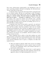
The three golden rules for pouring concrete on site
Construction details have a heavy impact on the actual quality of the concrete in a structure.
RULE No.1
CONCRETE MUST BE CAST INTO ITS FINAL POSITION ACROSS AN ESSENTIALLY
VERTICAL PATH
Horizontal paths must be avoided. This must be taken into consideration in the design drawings
for reinforcing bar arrangements.
nn
75mm 75mm
25mm
-11--
RIGHT
WRONG
Figure (a)
Figure (b)
Figure (a) depicts the right way to reinforce a beam to ensure that the forms are filled speedily
and satisfactorily. If the bars are arranged as depicted in Figure (b), the coarse aggregate will
not pass readily between them. As a result, the concrete will have to flow horizontally, inducing
segregation and lengthening the time needed to fill the formwork. Moreover, such arrangements leave insufficient space for the vibrator.
Concrete should not be dumped in a pile for subsequent spreading with vibrators. Rather, it
should be poured in each and every spot where it is needed.
xxvii
RULE No. 2
THE VIBRATOR MUST BE ABLE TO REACH THE BOTTOM REINFORCEMENT
Figure (c) shows the right way to reinforce a beam. With 65-mm spacing (somewhat smaller on
site due to the height of the ribs), a standard 50-mm vibrator will be able to reach the bottom
reinforcement. The solution depicted in Figure (d) is wrong, for it leaves insufficient room for
the vibrator.
65mm
41mm 41mm 41mm
65mm
--n nn-
MM
·~·
E
g
E
E
E
e. 06
E
e.0 6
0
0
0
0
LO
LO
2 016
212116
E
E
E
E
01
0
~
30
m~
.
(')
-+--(22 mm
~mm _
I
30ml11_j---l-
__j
~250mm
RIGHT. The vibrator can be
readily introduced into the
beam and the joint.
I 30mm
.
WRONG. The vibrator cannot
be introduced into the beam or
the joint.
Figure (c)
Figure (d)
Figures (e) and (f) show two further cases in which the vibrator is able, or unable, to reach the
bottom reinforcement.
30 mm
I
300 mm
.
i
1
130 mm
E
E
0
(')
E
E
0
0
LO
E
E
49m~h-j~mm
~49mm
RIGHT. The vibrator reaches the
bottom layer of reinforcement.
WRONG. The vibrator cannot
reach the bottom layer of
of reinforcement.
Figure (e)
Figure (f)
xxviii
RULE No. 3
CONCRETE CONSISTENCY MUST BE IN KEEPING WITH THE REINFORCEMENT
ARRANGEMENT. AS A GENERAL RULE THE CONCRETE SLUMP SHOULD BE NO
SMALLER THAN 60 mm
Unless the reinforcement is arranged very openly and spaciously or powerful vibration methods
are used, overly dry concrete is characterised by the following.
•
The required strength can be reached in test specimens (but not on site) with a lower proportion of cement. The real strength of concrete can be lower.
•
Since the control specimens can be compacted with no difficulty, the laboratory trials will
furnish good information.
•
In situ placement and a good surrounding of the reinforcement will be difficult to achieve and
the loose consistency will lower actual on-site strength.
xxix
1 General rules for bending, placing,
anchoring and welding reinforcing bars
1 INTRODUCTION
The present summary, based largely on Eurocode 2 (EC2), covers details of a general nature
whose inclusion in all the relevant chapters of this book would be unnecessarily repetitious.
Nonetheless, certain characteristics specific to each type of structural member are addressed
in the respective chapters.
Eurocode 2 (EC2) is supplemented by a number of other standards, the following in particular:
EN 10080
EN ISO 17760
EN ISO 3766:2003
Eurocode 8
Steel for the reinforcement of concrete (1)
Permitted welding process for reinforcement (2)
Construction drawings. Simplified representation of concrete reinforcement (3)
Design of structures for earthquake resistance (4).
Further to EC2 (5), for buildings located in seismic areas, the construction details in this and the
following chapter may be modified as described in Chapter 2, Group 15 below.
1.1
SUMMARY OF CODES AND STANDARDS ON CONSTRUCTION DETAILS
1.1.1
PERMISSIBLE MANDREL DIAMETERS FOR BENT BARS (see EC2, 8.3)
EC2 (5) stipulates that:
•
•
the minimum diameter to which a bar may be bent shall be defined as the smallest diameter
at which no bending cracks appear in the bar and which ensures the integrity of the concrete
inside the bend of the bar;
in order to avoid damage to the reinforcement, the diameter to which the bar is bent (mandrel diameter) should not be less than
1
TABLE T-1.1
MINIMUM MANDREL DIAMETER TO PREVENT DAMAGE
TO REINFORCEMENT (EC2)
(a)
(b)
for bars and wire
Bar diameter
Minimum mandrel diameter for bends, hooks and loops
4
</J>16mm
7
for bent welded reinforcement and wire mesh bent after welding
Minimum mandrel diameter
(
•
or
<•
(
WW
or
/
d ~ 3
5
The mandrel diameter need not be checked to avoid concrete failure if the following conditions
exist:
•
•
•
the length of the bar anchorage beyond the end of the bend is not over 5 the bar is not in an end position (plane of bend close to concrete face) and a cross bar with a
diameter ~
the mandrel diameter is at least equal to the recommended values given in Table T-1.1.
Otherwise, the mandrel diameter, [1.1]
where:
Fbt
ab
The value of
is the tensile force of the ultimate loads in a bar or bundle of bars at the start of
a bend
for a given bar (or group of bars in contact) is half of the centre-to-centre distance between bars (or groups of bars) perpendicular to the plane of the bend.
For a bar or bundle of bars adjacent to the face of the member, ab should be
taken as the cover plus
must not be taken to be greater than the value for class C55/67 concrete.
2