Electrical safety handbook
Bạn đang xem bản rút gọn của tài liệu. Xem và tải ngay bản đầy đủ của tài liệu tại đây (11.49 MB, 191 trang )
Other Books of Interest
Croft, Summers • AMERICAN ELECfRICIANS' HANDBOOK
Denno • ELECfRIC PROTECI1VE DEVICES
Johnson • ELECfRICAL CONTRACI1NG BUSINESS HANDBOOK
Johnson • SUCCESSFUL BUSINESS OPERATIONS FOR ELECfRICAL CONTRACTORS
Kolstad • RAPID ELECfRICAL ESTIMATING AND PRICING
Kusko • EMERGENCY/STANDBY POWER SYSTEMS
Linden • HANDBOOK OF BATTERIES AND FUEL CELLS
Lundquist. ON-LINE ELECfRICAL TROUBLESHOOTING
McPartland· MCGRAW-HILL'S NATIONAL ELECfRICAL CODE~ HANDBOOK
McPartland • McGRAW-HILL'S HANDBOOK OF ELECTRICAL CONSTRUCI10N
CALCULATIONS
McPartland· HANDBOOK OF PRACTICAL ELECfRICAL
Pete • ELECTRIC POWER SYSTEMS MANUAL
Richter, Schwan • PRACTICAL ELECfRICAL WIRING
Seidman, Mahrous, Hicks • HANDBOOK OF ELECfRIC
Smeaton • SWITCHGEAR AND CONTROL HANDBOOK
Traister· DESIGN AND APPLICATION OF SECURITY/FIRE
DESIGN
ELECTRICAL
SAFETY HANDBOOK
John Cadick,
P.E.
Cadick Professional Services, Garland, Texas
POWER CALCULATIONS
ALARM SYSTEMS
McGRAW-Hill, INC.
New York San Francisco Washington, D.C.
Auckland Bogota
Caracas Lisbon London Madrid
Mexico City Milan
Montreal New Delhi San Juan Singapore
Sydney Tokyo Toronto
Library
of Congress
Cataloging.in·Publication
Cadick, John.
Electrical safety handbook / John Cadick.
p.
em.
Includes index.
ISBN 0-07-009514-0 (alk. paper)
1. Electric engineering-8afety
measures.
I. Title.
TK152.C22
1994
621.319'028'9-dc20
Data
2. Industrial
safety.
94-13347
CIP
Copyright © 1994 by McGraw-Hill, Inc. All rights reserved. Printed in the
United States of America. Except as permitted under the United States
Copyright Act of 1976, no part of this publication may be reproduced or distributed in any form or by any means, or stored in a data base or retrieval
system, without the prior written permission of the publisher.
2 3 4 5 6 7 8 9 0
DOC/DOC
9098765
ISBN 0-07-009514-0
The sponsoring editor for this book was Harold B. Crawford, the editing
supervisor was Paul R. Sobel, and the production supervisor was Pamela A.
Pelton. It was set in Times Roman by North Market Street Graphics.
Printed and bound by R. R. Donnel/ey & Sons Company.
Information contained in this work has been obtained by McGrawHill, Inc., from sources believed to be reliable. However, neither
McGraw-Hill nor its authors guarantees the accuracy or completeness of any information published herein, and neither
McGraw-Hill nor its authors shall be responsible for any errors,
omissions, or damages arising out of this information. This work
is published with the understanding that McGraw-Hill and its
authors are supplying information, but are not atfempting to render engineering or other professional services. If such services are
required, the assistance of an appropriate professional should be
sought.
This book was printed on acid-free paper.
To my father, Ross M. Cadick, who taught me
how to work and to pursue excellence; my
mother, Melba K. Cadick, who taught me how to
have fun; my wife, Sheryl Cadick, who taught me
patience; my children, Ross, Anna, Jessica, and
Julia, who have kept me young; and my friend,
Thad Brown, who taught me how to do business
and still be kind to people
CONTENTS
Preface
xi
1.1
Chapter 1. Hazards of Electricity
Introduction / 1.1
Hazard Descriptions / 1.1
Affected Body Parts / 1.9
Summary of Causes-Injury and Death
Protective Strategies / 1.14
/ 1.14
Chapter 2. Electrical Safety Equipment
2.1
Introduction / 2.1
Flash and Thermal Protection / 2.1
Head and Eye Protection / 2.8
Rubber-Insulating Equipment / 2.11
Hot Sticks / 2.38
Insulated Tools / 2.42
Barriers and Signs / 2.43
Safety Tags, Locks, and Locking Devices / 2.46
Voltage-Measuring Instruments / 2.49
Safety Grounding Equipment / 2.57
Ground Fault Circuit Interrupters / 2.68
Safety Electrical One-Line Diagram / 2.70
The Electrician's Safety Kit / 2.72
Chapter 3. Safety Procedures and Methods
Introduction / 3.1
The Six-Step Safety Method / 3.1
Safe Switching of Power Systems / 3.3
Energy Control Programs / 3.21
Tagout-Lockout / 3.24
Voltage-Measurement Techniques / 3.30
Placement of Safety Grounds / 3.35
General Work Area Safety / 3.43
Tools and Test Equipment / 3.47
The One-Minute Safety Audit / 3.50
3.1
viii
CONTENTS
Chapter 4. Regulatory and Legal Safety Requirements
and Standards
CONTENTS
4.1
Introduction / 4.1
The Regulatory Bodies / 4.1
The National Electrical Safety Code (NESC)-ANSI C-2 / 4.13
The National Electrical Code (NEC)-ANSIINFPA
70 / 4.15
Electrical Equipment Maintenance-ANSIINFPA
70B / 4.16
Electrical Safety Requirements for Employee Workplaces_
ANSIINFPA 70E / 4.17
The American Society for Testing and Materials (ASTM) Standards
Occupational Safety and Health Administration (OSHA) Standards
Chapter 9. Safety Training Methods and Systems
Introduction / 9.1
Elements of a Good Training Program / 9.3
On-the-Job Training / 9.6
Training Consultants and Vendors / 9.9
Training Program Setup-a Step-by-Step Method
/ 4.19
/ 4.19
Index (follows Chapter 91
Chapter 5. Accident Prevention, Accident Investigation,
Rescue, and First Aid
5.1
Accident Prevention / 5.1
First Aid / 5.5
Rescue Techniques / 5.18
Accident Investigation / 5.39
Chapter 6. Low-Voltage
Safety Synopsis
6.1
Introduction / 6.1
Low-Voltage Equipment / 6.2
Grounding Low-Voltage Systems / 6.5
Safety Equipment / 6.14
Safety Procedures / 6.19
Chapter 7. Medium- and High-Voltage
Safety Synopsis
Introduction / 7.1
High-Voltage Equipment / 7.1
Grounding Systems of over 1000 V / 7.3
Safety Equipment / 7.8
Safety Procedures / 7.12
Chapter 8. Safety Management
Structure
7.1
and Organizational
Introduction / 8.1
Electrical Safety Program Development
Employee Participation / 8.5
Safety Meeting / 8.6
Outage Reports / 8.8
Safety Audits / 8.8
8.1
/ 8.1
ix
1.1
/ 9.12
9.1
PREFACE
Each year hundreds of people are killed and hundreds more are injured by electrical energy. Many, if not most, of these deaths and injuries could be prevented by the
use of appropriate electrical safety techniques and equipment.
The book was written as a reference for personnel working on or near electrical
circuits of any voltage level. Safety personnel, electricians, line workers, engineers,
and supervisors will find the book to be an invaluable aid to safe and efficient work
with electrical energy systems. Management and safety training personnel will also
find sections which aid them in the setup and implementation of organizational and
training programs.
Chapter 1 provides an overview of an often overlooked aspect of electrical
safety-the nature of the hazard. Many accidents could be prevented if personnel
were simply made aware of how and why electricity is dangerous.
Chapters 2 and 3 present equipment and procedures that are used throughout
the electrical industry. The information in these two chapters can be used in the
development of electrical safety programs for utility, industrial, and commercial
electrical workers.
Chapter 4 identifies both consensus and mandatory standards and standards
organizations. Referral to this chapter will provide the reader with information
about the codes and standards which regulate the way that electrical work is performed. Of course, the reader should always refer to the current versions of all of the
standards which are described in Chapter 4. Standards covered include the National
Electrical Safety Code, the National Electrical Code, American Society of Testing
and Materials, and other key publications and organizations. Complete listings of
some standards are included.
Chapter 5 focuses on what to do if an accident does happen. Starting with a
detailed description of accident prevention concepts, this chapter then provides the
reader with information on rescue, first aid, and accident investigation. The proper
investigation of accidents is a science that should only be performed by qualified,
experienced personnel. Chapter 5 describes what to do, and perhaps more importantly, what not to do during an accident investigation.
Low voltage circuits can be just as deadly as high voltage circuits. Chapters 6 and
7 define the key elements of electrical safety for low voltage and medium/high voltage circuits respectively. Readers will be surprised at how little difference exists
between low and mediumlhigh voltage safety.
Management often loses sight of its obligation in the provision of a safe work
environment. A well structured, safe work place goes beyond simply obeying the
law. Chapter 8 describes the elements of a well structured, efficient electrical safety
program. Managers may refer to this chapter for direction during the setup and or
modification of a company safety program.
Procedures, equipment, programs, and rules can never replace well trained, competent personnel. Chapter 9 presents information that will allow the setup, implementation, and evaluation of a successful electrical safety training program.
xii
PREFACE
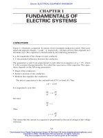
CHAPTER 1
This Electrical Safety Handbook presents, for the first time, a comprehensive
guide to electrical safety equipment, procedures, training, and standards.
ACKNOWLEDGMENTS
HAZARDS OF ELECTRICITY
._---~-
The author gratefully acknowledges the following: Kathy Hooper, ASTM; Robert
L. Meltzer, ASTM; Laura Hannan, TEGAM, Incorporated; Raymond L. Erickson,
Eaton Corporation, Cutler-Hammer Products; H.G. Brosz, Brosz and Associates
Archives; P. Eng, Brosz and Associates Archives; Ellis Lyons, W.H. Salisbury and
Co.; Tom Gerard, TIF Instruments, Inc., Miami, FL; LaNelle Morris, Direct Safety
Company, Phoenix, Arizona; Tony Quick, Santronics Inc.; Ed DaCruz, Siebe North,
Inc.; Benjamin L. Bird, CIP Insulated Products; E.T. Thonson, AVO Biddle Instruments, Blue Bell, PA; Terry Duchaine, Ideal Industries, Inc., Sycamore, IL; Mary
Kay S. Kopf, DuPont Fibers; Stephen Gillette, Electrical Apparatus Division of
Siemens Energy and Automation, Inc.; Mary Beth Stahl, Mine Safety Appliances
Company; Debbie Prikryl, Encon Safety Products; Craig H. Seligman, NOMEX ®
III Work Clothing, Workrite Uniform Company, Oxnard, CA; Kareem M. Irfan,
Square D Company, A.B. Chance Co., AVO Multi-Amp Institute; Alan Mark
Franks; and Sandy Young.
John Cadick
INTRODUCTION
Understanding the steps and procedures employed in a good electrical safety program requires an understanding of the nature of electrical hazards. Although they
may have trouble writing a concise definition, most people are familiar with electric
shock. This often painful experience leaves its memory indelibly etched on the
human mind. However, shock is only one of the electrical hazards. There are two
others-arc and blast. This chapter describes each of the three hazards and explains
how each affects the human body.
Understanding the nature of the hazards is useless unless protective strategies
are developed to protect the worker. This chapter also includes a synopsis of the
types of protective strategies that should be used to protect the worker.
HAZARD DESCRIPTIONS
Shock
Description. Electric shock is the physical stimulation that occurs when electric
current passes through the body. The effect that electric shock has on the body
depends on the magnitude of the current flow, the body parts through which the current flows, and the general physical condition of the person being shocked.
Current Magnitude. The magnitude of the current which flows through the body
generally obeys Ohm's law, that is,
where I = current magnitude, amperes (A)
E = applied voltage, volts (V)
R = resistance of path through which current flows, ohms (Q)
In Fig. 1.1 the worker has contacted a 120-V circuit when an electric drill shortcircuits internally. The internal short circuit impresses 120 V across the body of the
worker from the hand to the feet. This creates a current flow through the worker to
the ground and back to the source. The total current flow in this case is given by the
formula
1.1
Table 1.3 lists the effects that various currents will have on a 68-kilogram (kg)
human being. The current flow of 21.1 mA is sufficient to cause the worker to go into
an "electrical hold." This is a condition wherein the muscles are contracted and held
by the passage of the electric current-the
worker cannot let go. Under these circumstances, the electric shock would continue until the current was interrupted or
until someone intervened and freed the worker from the contact. Unless the worker
is freed quickly, tissue and material heating will cause the resistances to drop, resulting in an increase in the current. Such cases are frequently fatal.
Parts of the Body. Current flow affects the various bodily organs in different manners. For example, the heart can be caused to fibrillate with only 75 mA. The
diaphragm and the breathing system can be paralyzed, which possibly may be fatal,
with less than 30 mA of current flow. The specific responses of the various body
parts to current flow are covered in later sections.
1.4
CHAPTER ONE
HAZARDS OF ELEcrRICITY
TABLE 1.3 NominalHuman Response to Current Magnitudes'
Current (60Hz)
1-3 mA
3-10 mA
IOmA
Physiologicalphenomena
Imperceptible
Mild sensation
Painful sensation
Paralysisthreshold of arms
Cannot release hand grip;if no grip,
victimmay be thrown clear (may
progress to higher current and be
fatal)
Stoppage of breathing (frequently
fatal)
Respiratory paralysis
75mA
Fibrillationthreshold 0.5%
250mA
4A
Fibrillationthreshold 99.5%
(~ 5-s exposure)
Heart paralysisthreshold
(no fibrillation)
~5A
Tissueburning
Arcs can be started in several ways:
Feelingor lethal incidence
None
Perception threshold
30mA
1.5
Heart action discoordinated(probably fatal)
Heart stops for duration of current
passage.For short shocks,may
restart on interruption of current
(usuallynot fatal from heart dysfunction)
Not fatal unlessvital organs are
burned
• Notes: (I) This data is approximate and based on a 68-kg (150-lb) person. (2) Information for higher current levels is obtained from data derived from accident victims. (3) Responses are nominal and will vary
widely by individual.
Source: Courtesy of Ralph Lee.
General Physical Condition. The physical condition of the individual greatly
modifies the effects of current flow. A person in good physical condition will be
affected much less severely than a person in poor health by the same amount of current flow. If the individual has any specific problems such as heart or lung ailments,
these parts of the body will be severely affected by relatively low currents. For example, an individual who suffers from heart rhythm problems is more likely to develop
fibrillation than one with a healthy heart.
Bums. Electric current can cause severe tissue damage through burning. Burns
caused by electric current are almost always third-degree because the burning occurs
from the inside of the body. This means that tbe growth centers are destroyed. Electric-current burns can be severe when they involve vital internal organs.
• When the voltage between two points exceeds the dielectric strength of the air. This
can happen when overvoltages due to lightning strikes or switching surges occur.
• When the air becomes superheated with the passage of current through some conductor. For example, if a very fine wire is subjected to excessive current, the wire
will melt, superheating the air and causing an arc to start.
• When two contacts part when they are carrying a very high current. In this case,
the last point of contact is superheated and an arc is created because of the inductive flywheel effect.
Electric arcs are extremely hot. Temperatures at the terminal points of the arcs
can reach as high as 50,000 kelvin (K). Temperatures away from the terminal points
are somewhat cooler but can still reach 20,000 K. These high temperatures can cause
fatal burns at distances of up to 8 feet (ft) or more. Even if the direct burns are not
immediately fatal, clothing can be ignited which can cause fatal secondary burns.
The amount of energy, and therefore heat, in an arc is proportional to the maximum available short circuit volt-amperes in the system at the point of the arc. It has
been shown that the maximum arc energy is equal to one-half of the available fault
volt-amperes at any given point. Since the amount of arc energy determines that
degree of heat and, therefore, the degree of injury, the system voltage level has only
a minimal effect on the arc hazard. Low-voltage systems have just as significant an
arcing hazard as high-voltage systems.
Four major factors determine the effect of an electric arc on the exposed person
or object. Table 1.4 describes each of these factors. Figures 1.2 and 1.3 show the
results of two experiments that were conducted with manikins exposed to electric
arcs. As can be seen, both high and low voltages can create sig.nificant burns.
Arc Bums.
Arc burns are thermal in nature and, therefore, fall into one of the
three classical categories:
• First-degree burns. First-degree burning causes painful trauma to the outer layers of the skin. Little permanent damage results from a first-degree burn because
all the growth areas survive. Healing is usually prompt and leaves no scarring.
• Second-degree burns. Second-degree burns result in relatively severe tissue
damage and blistering. If the burn is to the skin, the entire outer layer will be
destroyed. Healing occurs from the sweat glands and/or hair follicles.
TABLE 1.4 FactorswhichEffect Injuries Due to Electric Arc
Distance
Arc
Definition and Description.
Electric arcing occurs when a substantial amount of
electric current flows through what previously had been air. Since air is not a conductor, the current flow is actually occurring through the vapor of the arc terminal
material and the ionized particles of air. This mixture of materials, through which
the arc current flows, is called a plasma.
Absorption coefficient
Temperature
Time
The amount of damage done to the recipient diminishesas the
square of the distance from the arc. 1\vice as far means onefourth the damage
Different materials willabsorb different amounts of radiant heat
The greater the temperature, the greater the injury potential
The longer the exposure, the greater the damage. If protective
systemsoperate quickly,the exposure and therefore the injury
willbe reduced
1.8
CHAPTER ONE
• Third-degree burns. Third-degree burns to the skin result in complete destruction of the growth centers. If the burn is small, healing may occur from the
edges of the damaged area; however, extensive third-degree burns require skin
grafting.
Blast
When an electric arc occurs, it superheats the air instantaneously. This causes a rapid
expansion of the air with a wavefront that can reach pressures of 100 to 200 pounds
per square foot (lb/fe). Such pressure is sufficient to explode switchgear, turn sheet
metal into shrapnel, turn hardware into bullets, push over concrete walls, and blow
molten metal at extremely high velocities.
Blasts do not always occur. Sometimes an arc is not accompanied by a blast, but
when it is, it can be lethal. Figure 1.4 shows physical evidence of the pressure exerted
by an electric blast.
HAZARDS OF ELECTRICITY
1.9
AFFECTED BODY PARTS
Skin
Definition and Description. Skin is the outer layer which completely encloses and
envelopes the body. Each person's skin weighs about 41b, protects against bacterial
invasion and physical injury of underlying cells, and prevents water loss. It also provides the body with sensation, heat regulation, excretion (sweat), and absorbs a few
substances. There are about 20 million bacteria per square inch on the skin's surface
as well as a forest of hairs, 50 sweat glands, 20 blood vessels, and more than WOO
nerve endings. Figure 1.5 is a cross section of the upper layers of skin tissue.
The main regions of importance for electrical purposes are the horny layer, the
sweat glands, and the blood vessels. The horny layer is composed primarily of a pro-
1.10
CHAPTER
ONE
tein material called keratin. Keratin exhibits the highest resistance of all the skin
parts to the passage of electricity. The sweat glands and the blood vessels have relatively low resistances to the passage of electricity and provide a major means of
access to the wet, fatty inner tissues. As you can see from Table 1.1, most of the electrical resistance exhibited by the human body is centered on the external skin layers-the horny layer.
Effects on Current Flow. Since the body is a conductor of electricity, Ohm's law
applies as it does to any other physical substance. The thicker the horny layer, the
greater the skin's electrical resistance. Workers who have developed a thick horny
layer have a much higher resistance to electricity than a child with an extremely thin
layer. However, as Table 1.1 shows, even high skin resistance is not sufficient to protect workers from electric shock.
Skin resistance is also a function of how much skin area is in the circuit. Therefore, grasping a tool with the entire hand gives a much lower resistance than touching the tool with a finger. Also, any cut or abrasion penetrates the outside horny
layer and significantly reduces the total resistance of the shock circuit. Moisture,
especially sweat, greatly reduces the skin's resistance. A remarkable thing occurs to
the skin insulation when voltages around 600 V are applied. At these voltages the
horny layer is punctured like any film insulation, and only the low-resistance inner
layers are left. This is an extremely important phenomenon to take into consideration in commercial and industrial power systems because of the high proliferation of
480-V distribution systems. Note that the horny layer may not puncture, but if it
does, the current flow increases and shock injury is worse.
Bums.
Electrical skin bums can come from two different sources. Current flow
through the skin can cause bums from the [2R energy. Thermal or radiation bums
are caused by the radiant energy of the electric arc as shown in Fig. 1.6.
The Nervous System
Definition and Description. The nervous system is comprised of the electrical
pathways that are used to communicate information from one part of the human
body to another. To communicate, electric impulses are passed from one nerve to
another. For example, the heart beats when an electric impulse is applied to the muscles which control it. If some other electric impulse is applied, the nervous system
can become confused. If the current is high enough, the damage can be permanent.
Shock. As far as the nervous system is concerned, at least three major effects can
occur when current flows through the body:
• Pain. Pain is the nervous system's method of signaling injury. When current
flows through the nerves, the familiar painful, tingling sensation can result.
• Loss of control. An externally applied current can literally "swamp" the normal
nervous system electric impulses. This condition is similar to electrical noise covering an information signal in a telemetering or other communications system.
When this happens, the brain loses its ability to control the various parts of the
body. This condition is most obvious during the electrical paralysis, or electrical
hold, that was described previously in this chapter.
• Permanent damage. If allowed to persist, electric current can damage the nervous system permanently. This damage takes the form of destroyed neurons
and/or synapses. Since the nervous system is the communications pathway used to
control the muscles, such damage can result in loss of sensation and/or function
depending on the type of injury.
Muscular System
Definition and Description.
The muscular system provides motor action for the
human body. When the nervous system stimulates the muscles with electric
impulses, the muscles contract to move the body and perform physical activity. The
heart and pulmonary system are also muscle related. They will be covered in a later
section.
1.12
Shock.
CHAPTER
ONE
Electrical shock can affect muscles in at least three significant ways:
• Reflex action. Muscular contractions are caused by electric impulses. Normally
these impulses come from the nervous system. When an externally induced current flows through a muscle, it can cause the muscle to contract, perhaps violently.
This contraction can cause workers to fall off of ladders or smash into steel doors
or other structures.
• Electrical paralysis. Current magnitudes in excess of 10 mA are sufficient to
block the nervous system signals to the muscular system. Thus, when such an
external current is flowing through the body, the victim may be unable to control
his or her muscles. This means that the victim cannot let go-he or she is caught in
an electrical hold. As the current continues, the heating and burning action can
lower the path resistance and cause an increase in the current. If the current is not
cut off or if the victim is not freed from the circuit, death will occur.
• Permanent damage. If the current is high enough, the muscle tissue can be
destroyed by burning. Currents of even less than 5 A will cause tissue destruction
if they last long enough. Because such burning destroys the growth areas in tissue,
the damage can be extremely slow to heal. Physical therapy and other extraordinary methods may be required to restore muscular function.
The Heart
Definition and Description.
The heart is a fist-sized pump that beats more than
2.5 billion times in a 75-year lifetime. Even a few minutes of heart failure can cause
death. Figure 1.7 shows the structural layout of the heart. High on the right arterial
wall, a tiny bundle of nerve tissue called the sinus node ignites an impulse that races
across the wall and down to the atrioventricular (AV) node, a cell cluster at the gateway to the ventricles. In the wake of this impulse, a contraction ripples the atrium,
sending blood to the heart's lower chambers.
The AV node, in turn, flashes the spark through the conduction pathways into a
nerve network that lines the ventricles. The spark leaps across the ventricle's muscle
fibers at almost 7 feet per second (ft/s). The resulting contraction sends blood flowing from the heart.
A set of backup devices sustains the heart's electrical system in times of need. If
the sinus node fails, the AV node initiates the heartbeat. There are even special muscle cells that can deliver an impulse if the AV node does not.
Shock. When the heart's electrical system is disturbed for any reason, such as an
outside current from an electric power shock, the whole process can fail. In fact,
electrical disruptions cause a large percentage of heart deaths.
The electric impulses in the heart must be coordinated to give a smooth, rhythmic beat. An outside current of as little as 75 mA can disturb the nerve impulses so
that there is no longer a smooth, timed heartbeat. Instead the heart fibrillates-that
is, it beats in a rapid, uncoordinated manner. When a heart is fibrillating, it flutters
uselessly. If fibrillation is not ended quickly, death will follow.
Like any muscle, the heart will become paralyzed if the current flowing through
it is of sufficient magnitude. Oddly, paralysis of the heart is not often fatal if the current is removed quickly enough. In fact, such paralysis is used to an advantage in
defibrillators. A defibrillator intentionally applies heart-paralyzing current. When
the current is removed, the heart is in a relaxed state ready for the next signal. Frequently the heart restarts.
Bums. Burnt heart muscle often can be fatal depending upon the amount of tissue
burnt and which part of the heart is affected. Like all electric current burns, heart
burns are frequently third-degree burns.
The Pulmonary System
Definition and Description.
With the exception of the heart, the pulmonary system is the most critical to human life. If breathing stops, all other functions cease
shortly thereafter. When the lower diaphragm moves down, it creates a vacuum on
the chest chamber. This in turn draws air into the sacs in the lungs. The oxygen is
then passed to the bloodstream through the tiny capillaries. At the same time, carbon dioxide is returned to the air in the lungs. When the lower diaphragm moves up,
the air is forced out of the lungs, thus completing the breathing cycle.
Shock. Current flow through the midsection of the body can disrupt the nervous
system impulses which regulate the breathing function. This disruption can take the
form of irregular, sporadic breathing, or-if the current flow is sufficient-the pulmonary system may be paralyzed altogether. When such stoppage occurs, first aid is
often required.
1.14
CHAPTER ONE
HAZARDS OF ELECTRICITY
SUMMARY
OF CAUSES-INJURY
AND DEATH
TABLE 1.5
Hazards
Shock Effect
Table 1.3 summarizes the effects that electric shocks of varying amounts of current
will have on a 68-kg (150-lb) person.
Hazard
Shock
Causes of Injury
Injury from electrical hazard can come from both direct and indirect sources:
Arc
• The reflex action caused by the passage of current flow can cause falls resulting in
cuts, abrasions, or broken limbs.
• Nerve damage from shock or burns can cause loss of motor function, tingling,
and/or paralysis.
• Burns, both thermal- and current-induced, can cause extremely long duration and
intensely painful suffering. Third-degree burns may require skin grafting to heal.
• Molten metal and/or burns to the eyes can cause blindness.
• The concussion of a blast can cause partial or complete loss of hearing.
• Current-induced burns to internal organs can cause organ dysfunction.
Causes of Death
If the electrical injury is severe enough, death can result.
• An electric shock-induced fall can cause fatal physical injuries.
• When the skin is severely burnt, large quantities of liquid are brought to the burnt
areas to aid in the healing process. This creates a stress on the renal system and
could result in kidney failure .
• Severe trauma from massive burns can cause a general systemic failure.
• Burnt internal organs can shut down--causing death. Thus, the more critical the
organ that is burnt, the higher the possibility of death.
• If the victim inhales the superheated plasma and molten products from an electric
arc, the lungs will no longer be able to perform correctly. Death may follow.
• Heart failure can result from fibrillation and/or paralysis.
PROTECTIVE STRATEGIES
The types of strategies that may be employed to protect from each of the three electrical hazards are remarkably similar. Table 1.5 summarizes the types of protective
strategies that may be used. Note that the information given in Table 1.5 is general.
Specific equipment and procedures are covered in Chaps. 2 and 3.
Blast
1.15
Equipment and Procedural Strategiesfor Protection from the Three Electrical
Equipment strategy
• Rubber insulatingequipment
includinggloveswith leather
protectors, sleeves,mats, blankets, line hose, and covers
• Insulated tools when working
near energizedconductors
• NOMEX or other approved
flash/flame-resistantwork
clothing
• NOMEX or other approved
flash suits when performing
work with a high risk of arcing
• Use hot sticksto keep as much
distance as possible
• Wear eye protection
• Wear rubber gloveswith leather
protectors and/or other flashproof gloves
• NOMEX or other approved
flash/flame-resistantwork clothing.Thiswillprotect from
splashed molten material
• NOMEX or other approved
flash suits when performing
work with a high risk of arcing.
Thiswillprotect from splashed
molten material
• Wear face shields
Procedural strategy for all three hazards
• De-energize all circuitsand conductors in the immediatework area
• Develop and followa lockout/tagout
procedure
• Maintain a safe workingdistance
from all energizedequipment and
conductors
• Use all specifiedsafety equipment
• Followall safetyprocedures and
requirements
• Carefullyinspect all equipment
before placingit into service.This
includestools,test equipment, electrical distribution equipment, and safety
equipment.
• Make certain that all nonenergized
equipment is properly grounded.
Thisapplies to both normal system
groundingand temporary safety
grounds
Be aware that any given strategy may not be applicable in a given situation. For
example,
• When troubleshooting equipment, de-energization may not be possible.
• De-energization may create an additional, unacceptable hazard. For example, if
de-energization shuts down ventilation equipment in a hazardous area, workers
may opt for working with energized equipment.
• Shutdown of an entire continuous process plan to work on or around one small
auxiliary circuit may not be economically feasible.
If equipment cannot be deenergized, workers must use procedures and safety equipment that will minimize the safety hazards to the greatest extent possible.
....'_~ _ _n._
CHAPTER 2
ELECTRICAL SAFETY
EQUIPMENT
INTRODUCTION
The safety aspects of any job or procedure are greatly enhanced by the use of proper
tools and equipment. This chapter outlines the construction and use of a variety of
electrical safety equipment. Some of the equipment is used to actually perform
work-items such as insulated tools or voltage-measuring devices fall into this catelOry. Other safety products are used strictly to protect the worker, for example, flash
luitsandrubbergood&
Each specific piece of safety equipment is used to protect the worker from one or
more of the three electrical safety hazards, and each piece of equipment should be
employed when performing various types of jobs in the electric power system.
Always make certain the equipment you are using is designed for the application
and the voltage to which you will be exposed.
The guidelines for wearing and/or using the various types of equipment discussed
in this chapter should be considered minimum guidelines. Requirements for specific
locations should be determined on a case-by-case basis.
FLASH AND THERMAL PROTECTION
The extremely high temperatures and heat content of an electric arc can cause
extremely painful and/or lethal bums. Since an electric arc can occur at any time, the
worker must wear protection when exposed to potential arc hazards. Note that these
lections address equipment for electrical hazard. Fire protection equipment has
slightly different requirements and is not covered.
Thble 2.1 itemizes the type of equipment required to protect the worker from the
thermal hazards of electric arc. The next sections describe the type of equipment
used and will identify when and how to use that equipment.
Clothing Materials
Materials used to make industrial clothing fall into four basic categories: synthetic
materials, synthetic-cotton blends, 100 percent cotton, and specially designed,
flame-retardant materials. These materials provide varying degrees of protection
2.1
ELECTRICAL
SAFETYEQUIPMENT
CHAPTERTWO
2.2
TABLE 2.1
Equipment Used to Protect Workersfrom Arc Hazard
Area of body to be protected
Equipment used
Torso,arms,legs
Eyes
Head
Hands
Thermal work uniforms,flash suits
Faceshields,goggles,safety glasses
Insulatinghard hats, flash hoods
Rubber gloveswith leather protectors
from electric arcing. The following paragraphs describe the various materials and
combinations in ascending order of acceptability and safety.
Untreated synthetic clothing materials such as polyester and
Synthetic Materials.
nylon provide extremely poor thermal protection and should never be used when
working in areas where an electric arc may occur. Some synthetic materials actually
increase the danger of exposure to an electric arc. Synthetic materials have a tendency to melt into the skin when exposed to high temperatures. This melting causes
three major difficulties.
1. The melted material forms a thermal seal which holds in heat and increases the
severity of the burn.
2. Circulation is severely limited or cut off completely under the melted material.
This slows healing and retards the flow of normal nutrients and infection-fighting
white blood cells and antibodies.
3. The removal of the melted material is extremely painful and may increase the
trauma already experienced by the burn victim.
Synthetic-Cotton Blends. Synthetic-cotton blends such as polyester-cotton are
used to make clothing that is easier to care for. Although slightly less vulnerable to
melting than pure polyester, the blends are still extremely vulnerable to the heat of
an electric arc and the subsequent plasma cloud. Such blends provide poor thermal
protection and should not be used in areas where the hazard of electric arc exists.
Cotton. Cotton work clothing made of materials such as denim and flannel is a
better choice than clothing made from synthetic materials. Cotton does not melt into
the skin when heated; rather, it burns and disintegrates, falling away from the skin.
Thick, heavy cotton material provides a minimal barrier from arc temperatures and
ignites quickly. At best, cotton provides only fair thermal protection.
Chemically Treated Materials. Cotton and synthetic-cotton blends for work
clothing are available in chemically treated forms. Such materials are treated with a
flame-retardant chemical which slows combustion and provides an additional level
of protection from fire and heat. Chemically treated materials are often used in disposable, coverall-type clothing since the chemical treatment is degraded by repeated
washing.
Although chemically treated materials are not flammable, they offer only minimal resistance to the radiation energy of an electric arc. Such materials provide fair
to good thermal protection. Chemically treated materials are often referred to as
flame-retardant materials.
2.3
NOMEX* IlIA.
NOMEX is an aramid fiber made by the DuPont Company. It
has a structure that thickens and carbonizes when exposed to heat. This unique characteristic provides NOMEX with excellent thermal protection.
NOMEX has been modified in the years since it was first introduced. NOMEX
IlIA is made with an antistatic fiber and is, therefore, suitable for use in hazardous
environments such as those with high concentrations of hydrocarbon gas.
Since the characteristics of NOMEX are inherent to the fiber, and not a chemical
treatment, the thermal protection capabilities of NOMEX are not changed by
repeated laundering.
Polybenzimidazole (PBI). t PHI is a product of the Hoechst Celanese Corporation. It is similar to NOMEX in that it is a synthetic fiber made especially to resist
high temperatures. PHI is non-flammable, chemically resistant, and heat stable. This
heat stability makes it less prone to shrinking or embrittlement when exposed to
flame or high temperatures.
PHI does not ignite, melt or drip in Federal Vertical; Flame Tests FSTM 5903 and
FSTM 5905. PHI's characteristics are permanent for the life of the garment. Hoescht
Celanese performed tests indicate that PHI has heat protection characteristics which
are equal to or superior than other materials.
Material Comparisons.
Table 2.2 illustrates the relative properties of the various
types of clothing materials. The information given in Table 2.2 is drawn from general
industry experience and/or manufacturer experiments.
Figure 2.1 graphically illustrates the predicted, thermal performance of four of
the commonly used materials. To generate these numbers, a specially instrumented
* NOMEXisa registeredtrademarkoftheE. 1. DupontdeNemoursCompany.
t
PBIisa trademarkoftheHoeschtCelaneseCorporation.
TABLE 2.2
ClothingMaterial CharacteristicsComparison
Fiber property
Flammable
Flame
resistance
Thermal
protection
Care
Appearance after
10 washes
Nominallife (years)
Relative cost
Cost per year
* FR= flameresistant.
Cotton
Polyestercotton
Yes
None
Yes
None
Poor
FR * cotton
FR polyestercotton
Poor
No
Topical
treatment
Fair
No
Topical
treatment
Fair to good
Requires
ironing
Poor
Machine
wash/dry
Good
Requires
ironing
Poor
Touch-up
ironing
Good
Machine
wash/dry
Good
NOMEX
No
Inherent
Excellent
1
2-3
1
2
4-5
1
1
2
2.8
4
1
0.4
2
1.4
0.9
ELECTRICAL
SAFETY EQUIPMENT
2.5
1. Long sleeves to provide full arm protection
2. Heavy weight for both thermal and mechanical protection
The suggested minimum is 4 ounces per square yard (oz/yd2) if NOMEX or PBI is
used and 7 to 8 oz/yd2 if flame-retardant cloth or blends are used. Figure 2.3 shows
several examples of NOMEX work clothing.
2.6
CHAPTER TWO
When to Use Thermally Protective Work Uniforms. Thermally protective work
uniforms should be required for all workers who are routinely exposed to the possibility of electric arc and/or flash. This applies especially to workers in the industries
which have the added hazard of flash fire. At a minimum, all employees who are routinely exposed to 480 V and higher should use the thermally protective materials.
Care of Thermally Protective Work Uniforms. The following information is necessarily general in nature. Always refer to the manufacturer's care and laundering
instructions for specific information. Work uniforms should be kept clean and free
of contaminants. Contaminated work clothing can be extremely hazardous. Table
2.3 lists typical care and use precautions for thermal work clothing and flash suits.
Flash Suits
Construction.
A flash suit is a thermal-protective garment made of a heavierweight NOMEX, PBI or other flame-retardant material. The flash suit shown in Fig.
2.4 is made with 10 ozlyd2 NOMEX. This garment provides protection for temperatures up to 450 degrees Fahrenheit (OF) [232 degrees Celsius (oq. (Note that the
450°F rating is a continuous ambient rating.) The flash suit has a short-term capability much in excess of this amount.
Flash suits are composed of a minimum of two parts-the face-shield/hood (Figs.
2.5 and 2.6) and the jacket (Fig. 2.4). Some flash suits are also supplied with pants.
The jackets should be securely sealed to prevent the entry of the superheated
plasma gas (see Fig. 2.7).
Using Flash Suits. Flash suits should be used anytime an employee is exposed to
a higher than normal possibility of electric arc. The procedures listed in Table 2.4 are
typical of those in which many companies require the use of flash suits; however,
specific rules should be developed for each company. Flash suits should always be
used in conjunction with adequate head, eye, and hand protection. Note that all work-I
ers in the vicinity of the arc potential should be wearing a flash suit.
Some facilities impose a current limitation on the rule as well. For example, one
large petrochemical company requires flash suits for the procedures listed in Table
2.2, but only when the circuit breaker feeding the circuit has an ampacity of 100 A or
greater.
TABLE 2.3
Care and Use Guidelinesfor Thermal Protective Clothing
• Clothing should not be allowed to become greasy and/or impregnated with flammable
liquids
• Launder accordingto manufacturer's instructions.Generally,home launderingin hot water
with a heavy-dutydetergent willbe effective
• Do not mixflame resistant garments with itemsmade of other materials in the same wash
• Do not use bleachesor other treatments unlessrecommended by the manufacturer
• Remember that laundering may degrade the chemicaltreatment on some flame-retardant
materials.Observe manufacturer's recommendationsas to how many washesconstitute the
life of the garment
• Inspect work uniforms and flash suits before each use. If they are contaminated, greasy,
worn, or damaged in any way,they should be cleaned or replaced as required
2.8
CHAPTERTWO
Head, Eye, and Hand Protection
When wearing flash suits, or whenever
exposed to arc hazard, employees
should wear full protection for the head,
eyes, and hands. Head and eye protection will be provided if the employee is
equipped with a flash suit. When not in a
flash suit, however, employees should
wear hard hats and eye shields or goggles. Hand protection should be provided by electrical insulating rubber
gloves covered with leather protectors.
HEAD AND EYE
PROTECTION
FIGURE 2.6 Face shield open.
(Courtesy
Encon Safety Products.)
Hard Hats
Construction and Standards.
In addition to wearing protection from falling
objects and other blows, electrical workers should be equipped with and should
wear hard hats that provide electrical insulating capabilities. Such hats should comply with the latest revision of the American National Standards Institute (ANSI)
standard Z89.1 which classifies hard hats into three basic classes.
Class A hard hats are intended to reduce the force of impact of falling objects
and to reduce the danger of contact with exposed low-voltage conductors. They
are proof-tested by the manufacturer at 2200 V phase-to-ground.
Class B hard hats are intended to reduce the force of impact of falling objects
and to reduce the danger of contact with exposed high-voltage conductors. They
are proof-tested by the manufacturer at 20,000 V phase-to-ground.
ELECTRICAL
SAFETYEQUIPMENT
TABLE 2.4
2.9
Procedures whichRequire the Use of Flash Suits
•
•
•
•
•
Operating open-air switcheson circuitsof 480V and higher
Open-door switchingand rackingof circuit breakers-480 V and higher
Removingand installingmotor starters in motor control centers-Z08 V and higher
Applyingsafetygrounds-480 V and higher
Measuringvoltage in any circuit which is uncertain or has exhibited problems-208 V and
higher
• Workingon or near any exposed,energizedconductors-Z08 V or higher
Class C hard hats are intended to reduce the force of impact of falling objects.
They offer no electrical protection.
Figure 2.8 shows two examples of class B hard hats. Note that a hard hat must be
a class A or class B hat to be used in areas where electrical shock may occur. The
label for a class B hard hat is shown in Fig. 2.9.
Use and Care. Electrically insulating class A or B hard hats should be worn by
workers anytime there is a possibility they will be exposed to shock, arc, blast,
mechanical blows, or injuries. Table 2.5 lists typical working conditions in which
workers should be wearing such protection.
All components of the hard hat should be inspected daily, before each use. This
inspection should include the shell, suspension, headband, sweatband, and any
accessories. If dents, cracks, penetrations, or any other damage is observed, the hard
hat should be removed from service. Class A and B hard hats may be cleaned with
warm water and soap. Solvents and other harsh cleaners should be avoided. Always
refer to the manufacturer's instructions for specific cleaning information.
Safety Glasses, Goggles, and Face Shields
The plasma cloud and molten metal created by an electric arc are projected at high
velocity by the blast. If the plasma or molten metal enters the eyes, the extremely
high temperature will cause injury and possibly permanent blindness. Electrical
workers exposed to the possibility of electric arc and blast should be equipped with
and should wear eye protection. Such protection should comply with the latest revision of ANSI standard Z87.1 and should be nonconductive when used for electric
arc and blast protection.
2.10
CHAPTERTWO
ELECTRICAL
SAFETYEQUIPMENT
Flash suit face shields (Figs. 2.4
through 2.6) will provide excellent face
protection from molten metal and the
plasma cloud. Goggles which reduce
the ultraviolet light intensity (Fig. 2.10)
are also recommended. Figure 2.11 is a
photograph of a worker with an insulating hard hat and protective goggles.
Use and Care. Eye and face protection should be worn by workers anytime they are exposed to the possibility
of electric arc and blast. Table 2.5 lists
typical situations where such protection might be required.
Face protection should be cleaned before each use. Soft, lint-free cloths and
warm water will normally provide the necessary cleaning action; however, most
manufacturers supply cleaning materials for their specific apparatus.
FIGURE 2.10 Ultraviolet-resistantsafetygoggles.(Courtesy Mine Safety Appliances Company.)
TABLE 2.5
Protection
2.11
Work SituationswhichRequire NonconductiveHead Protection and Eye
•
•
•
•
Workingclose to exposed,overhead energized lines
Workingin switchgear,close to exposed energized conductors
Anytimethat a flash suit is recommended (see Table 2.4)
Whenany local rules or recognizedstandards require the use of nonconductivehard hats or
eye protection
• Anytime there is a danger of head, eye, or face injury from electricshock, are, or blast
RUBBER-INSULATING EQUIPMENT
Rubber-insulating equipment includes rubber gloves, sleeves, line hose, blankets,
covers, and mats. Employees should use such equipment when working in an area
where the hazard of electric shock exists. This means anytime employees are working on or near an energized, exposed conductor, they should be using rubberinsulating equipment.
Rubber goods provide an insulating shield between the worker and the energized conductors. This insulation will save the workers' lives should they accidently contact the conductor. The American Society of Testing and Materials
(ASTM) publishes recognized industry standards which cover rubber insulating
goods.
Rubber Gloves
Description. A complete rubber glove
assembly is composed of a minimum of
two parts-the rubber glove itself and a
leather protective glove. In service, the
leather protector fits over the outside of
the rubber glove and protects it from
physical damage and puncture. Sometimes the glove set will include a sheer,
cotton insert that serves to absorb moisture and makes wearing the gloves more
pleasant. Figure 2.12 shows a typical set
of rubber gloves with leather protectors.
Caution: Rubber gloves should never be
used without their protective leather shells
unless specifically designed for such use.
Construction
and Standards. The
ASTM publishes four standards which
affect the construction and use of rubber
gloves.
1. Standard D 120 establishes manufacturing and technical requirements for
the rubber glove.
2.12
CHAPTER TWO
2. Standard F 696 establishes
leather protectors.
3. Standard
manufacturing
ELECfRICAL SAFETYEQUIPMENT
and technical
requirements
for the
F 496 specifies in-service care requirements.
4. Standard F 1236 is a guide for the visual inspection
such rubber insulating equipment.
Rubber Insulating Equipment Classifications, Use Voltages, and Test
of gloves, sleeves, and other
Rubber gloves are available in five basic voltage classes from class 0 to class 4 and
two different types: types I and II. Table 2.6 identifies each class, its maximum use
voltage, and the root-me an-square (rms) and direct current (dc) voltages that are
used to proof-test the gloves. Figure 2.13 shows the general design and dimensions
of rubber gloves. Rubber gloves are available in four standard lengths:
1. 10 in (267 mm)
2. 14 in (356 mm)
TABLE 2.6
Voltages
2.13
Class of insulating blankets
Nominal maximumuse voltage·
phase-phase, ac,
rms, max
AC proof-test
voltage, rms, V
DC proof-test
voltage, avg, V
0
1
2
3
4
1,000
7,500
17,000
26,500
36,000
5,000
10,000
20,000
30,000
40,000
20,000
40,000
50,000
60,000
70,000
• Note: The ac voltage (rms) classificationof the protectiveequipment designatesthe maximum
nominaldesignvoltageof the energizedsystemthat maybe safelyworked.The nominaldesignvoltage isequal to (1) the phase-to-phasevoltageon multiphasecircuitsor (2) the phase-to-groundvoltage on single-phasegrounded circuits.Except for Class 0 equipment, the maximum-usevoltageis
based on the followingformula:Maximum-usevoltage(maximumnominaldesign voltage) = 0.95
ac proof-test voltage-2000.
3. 16 in (406 mm)
4. 18 in (457 mm)
Table 2.7 lists minimum and maximum thicknesses for the five classes of gloves.
In addition to the voltage classes, rubber gloves are available in two different
types: type I which is not ozone-resistant
and type II which is ozone-resistant.
All rubber goods must have an attached, color-coded label subject to the minimum requirements
specified in Table 2.8. Figure 2.14 summarizes the voltage ratings
for rubber goods and illustrates the labels which are applied by one manufacturer.
TABLE 2.7
Rubber Glove Thickness Standard
Minimum thickness
In crotch
Other than crotch
Maximum thickness
Class of
Glove
mm
in
mm
in
mm
in
0
1
2
3
4
0.46
0.63
1.02
1.52
2.03
0.018
0.025
0.040
0.060
0.080
0.51
0.76
1.27
1.90
2.54
0.020
0.030
0.050
0.075
0.100
1.02
1.52
2.29
2.92
3.56
0.040
0.060
0.090
0.115
0.140
Souree:
TABLE 2.8
CourtesyASTM.
Labeling Requirements for Rubber Goods
• Color coding according to voltage class: class O-red,
yellow, class 3-green, class 4-orange.
• Manufacturer's name
• Voltage class (0, 1, 2, 3,4)
• Type
• Size (gloves only)
class I-white,
class 2-
ELECfRICAL
SAFETY EQUIPMENT
2.15
When to Use Rubber Gloves. Rubber gloves and their leather protectors should
be worn anytime there is danger of injury due to contact between the hands and
energized parts of the power system. Each of the work situations described in Table
2.5 should require the use of rubber gloves and their leather protectors.
How to Use Rubber Gloves. Rubber gloves should be thoroughly inspected and
air-tested before each use-.They may be lightly dusted inside with talcum powder or
manufacturer-supplied powder. This dusting helps to absorb perspiration and eases
putting them on and removing them. Caution: Do not use baby powder on rubber
gloves. Some baby powder products contain additives which can damage the glove
and reduce its life and effectiveness.
Rubber gloves should be applied before any activity which exposes the worker to
the possibility of contact with an energized conductor. Be certain to wear the leather
protector with the glove. Always check the last test date marked on the glove and do
not use it if the last test was more than 6 months earlier than the present date.
Rubber Mats
Description. Rubber mats are used to cover and insulate floors for personnel protection. Rubber insulating mats should not be confused with the rubber matting
used to help prevent slips and falls. This type of mat is sold by many commercial
retail outlets and is not intended for electrical insulation purposes. Rubber insulating mats will be clearly marked and labeled as such.
Insulating rubber matting has a smooth, corrugated, or diamond design on one
surface and may be backed with fabric. The back of the matting may be finished with
cloth imprint or other slip-resistant material.
Construction and Standards. The ASTM standard D-178 specifies the design,
construction, and testing requirements for rubber matting.
Rubber mats are available in five basic voltage classes from class 0 to class 4, two
different types, and three different subcategories. Table 2.6 identifies each class, its
maximum use voltage, and ac rms and dc voltages that are used to test them. Table
2.9 identifies each of the types and special properties for insulating mats. Table 2.10
identifies the thickness requirements for insulating mats, Table 2.11 identifies the
standard widths for insulating rubber matting.
Rubber mats must be clearly and permanently marked with the name of the manufacturer, type, and class. ASTM D-178 must also appear on the mat. This marking
is to be placed a minimum of every 3 ft (1 m).
TABLE 2.9
Typesand SpecialProperty Specificationsof Insulating Rubber Matting
Type I
TypeII
Composition
Made of any elastomer or combination of elastomericcompounds,
properly vulcanized
Subcategories
None
Made of any elastomer or
combinationof elastomeric
compoundswith one or more
of the specialproperties listed
by subcategory
A: Ozone resistant
B:Flame resistant
C: Oil resistant
2.16
CHAPTER TWO
ELECTRICAL
TABLE 2.10
ThicknessSpecificationsfor
InsulatingRubber Mats
Thickness
Class
0
1
2
3
4
Source:
mm
3.2
4.8
6.4
9.5
12.7
in
0.13
0.19
0.25
0.38
0.50
Tolerance
mm
0.8
0.8
0.8
1.2
1.2
in
0.03
0.03
0.03
0.05
0.05
TABLE 2.11
Standard Widthsfor
Insulating Rubber Matting
24± 0.5in
30± 0.5 in
36 ± 1.0in
48± 1.0in
(610± 13mm)
(760± 13mm)
(914± 25 mm)
(1220± 25 mm)
Courtesy ASTM.
When to Use Rubber Mats. Employers should use rubber mats in areas where
there is an ongoing possibility of electric shock. Because permanently installed rubber mats are subject to damage, contamination, and embedding of foreign materials,
they should not be relied upon as the sole source of electrical insulation.
How to Use Rubber Mats. Rubber mats are usually put in place on a permanent
basis to provide both electrical insulation and slip protection. Mats should be carefully inspected before work is performed which may require their protection. Rubber mats should only be used as a backup type of protection. Rubber blankets,
gloves, sleeves, and other such personal apparel should always be employed when
electrical contact is likely.
Rubber Blankets
Description.
Rubber blankets are rubber insulating devices that are used to cover
conductive surfaces, energized or otherwise. They come in a variety of sizes and are
used anytime employees are working in areas where they may be exposed to energized conductors.
Construction and Standards. The ASTM publishes three standards which affect
the construction and use of rubber blankets.
1. Standard D 1048 specifies manufacturing and technical requirements for rubber
blankets.
2. Standard F 479 specifies in-service care requirements.
3. Standard F 1236 is a guide for the visual inspection of blankets, gloves, sleeves,
and other such rubber insulating equipment.
Rubber blankets are available in five basic voltage classes (0 to 4), two basic
types (I and II), and two styles (A and B). Table 2.6 identifies each class, its maximum use voltage, and the ac rms and dc voltages that are used to proof-test the blankets. Table 2.12 lists standard blanket sizes, and Table 2.13 lists standard blanket
thicknesses.
Type 1 blankets are made of an elastomer which is not ozone-resistant. Type II
blankets are ozone-resistant. Both type 1 and type II blankets are further categorized into style A and style B. Style A is a nonreinforced construction, and style B
TABLE 2.12 Standard Blanket SizesLength and Width
Without slot mm (in.)
457by 910
(18 by 36)
560by 560
(22 by 22)
690by 910
(27 by 36)
910by 910
(36 by 36)
910by 2128
(36 by 84)
1160by 1160
(45.5by 45.5)
---.
With slot mm (in.)
560by 560
(22 by 22)
910by 910
(36 by 36)
1160by 1160
(45.5by 45.5)
Source:
SAFETY EQUIPMENT
2.17
TABLE 2.13 Rubber Blanket Thickness
Measurements
Thickness
Class
------._--~-------,,-._
0
1
2
3
4
Source:
mm
1.6to 2.2
2.6 to 3.6
2.8 to 3.8
3.0 to 4.0
3.2to 4.3
-------------
in.
_--0.06to 0.09
0.10to 0.14
0.11to 0.15
0.12to 0.16
0.13to 0.17
..
Courtesy ASTM.
Courtesy ASTM.
has reinforcing members built-in. The reinforcing members may not adversely affect
the insulating capabilities of the blanket.
Blankets have a bead around the entire periphery. The bead cannot be less than
0.31 in (8 mm) wide nor less than 0.06 in (1.5 mm) high. Blankets may have eyelets
to facilitate securing the blanket to equipment; however, the eyelets must not be
metal.
Rubber blankets must be marked either by molding the information directly into
the blanket or by means of an attached, color-coded label. The labeling is subject to
the minimum requirements specified in Table 2.8. Figure 2.14 summarizes the voltage ratings for rubber goods and illustrates the labels which are applied by one manufacturer.
When to Use Rubber Blankets.
Rubber blankets should be used anytime there is
danger of injury due to contact between any part of the body and energized parts of
the power system. Rubber blankets may be used to cover switchgear, lines, buses, or
concrete floors (Fig. 2.15). They differ from mats because they are not permanently
installed.
2.18
CHAPTER TWO
How to Use Rubber Blankets.
Rubber blankets should be thoroughly inspected
before each use. They may then be draped over metal conductors or buses or hung
to form insulating barriers.
Blankets should be applied befQre any activity which exposes the worker to the
possibility of contact with an energized conductor. Always check the last test date
marked on the blanket and do not use it if the last test was more than 1 year earlier
than the present date.
Rubber Covers
Description.
Rubber covers are rubber insulating devices that are used to cover
specific pieces of equipment to protect workers from accidental contact. They
include several classes of equipment such as insulator hoods, dead-end protectors,
line hose connectors, cable end covers, and miscellaneous covers. Rubber covers are
molded and shaped to fit the equipment for which they are intended.
Construction and Standards. The ASTM publishes three standards which affect
the construction and use of rubber covers.
1. Standard D 1049 specifies manufacturing and technical requirements for rubber
covers.
2. Standard F 478 specifies in-service care requirements.
3. Standard F 1236 is a guide for the visual inspection of blankets, gloves, sleeves,
and other such rubber insulating equipment.
Rubber covers are available in five basic voltage classes (0 to 4), two basic types
(I and II), and five styles (A, B, C, D, and E). Table 2.6 identifies each class, its maximum use voltage, and the ac rms and dc voltages that are used to proof-test the covers. Many varieties of rubber covers are available (Fig. 2.16). Their size and shape
are determined by the equipment that they are designed to cover. Refer to ASTM
standard D 1049 for complete listings of the various standard covers.
Type 1 covers are made of a properly vulcanized, cis-l,4-polyisoprene rubber
compound which is not ozone-resistant. Type II covers are made of ozone-resistant
elastomers. Both type 1 and II covers are further categorized into styles A, B, C, D,
and E. Table 2.14 describes each of the five styles.
TABLE 2.14
__
.•
A
B
C
D
E
_
How to Use Rubber Covers.
Rubber covers should be thoroughly inspected
before each use. They may then be applied to the equipment which they are
designed to cover. Any covers that appear to be defective or damaged should be
taken out of service until they can be tested.
Covers should be applied before any activity which exposes the worker to the
possibility of contact with an energized conductor. Covers which are used to connect
line hose sections should always be used when multiple line hose sections are
employed.
Stylesof Rubber Covers
Style
-.--.
When to Use Rubber Covers. Rubber covers should be used anytime there is danger of an injury due to contact between any part of the body and energized parts of
the power system.
.0
Description
Insulator hoods
Dead End Protectors
Line Hose Connectors
Cable End Covers
MiscellaneousCovers
.
Line Hose
Description.
Rubber covers must be marked either by molding the information directly into
the cover or by means of an attached, color-coded label. The labeling is subject
to the minimum requirements specified in Table 2.8. Figure 2.14 summarizes the
voltage ratings for rubber goods and illustrates the labels which are applied by one
manufacturer.
Rubber insulating line hoses are portable devices used to cover
exposed power lines and protect workers from accidental contact. Line hose segments are molded and shaped to completely cover the line to which they are affixed.
Construction and Standards.
The ASTM publishes three standards which affect
the construction and use of rubber line hose.
2.20
CHAPTER TWO
1. Standard D 1050 specifies manufacturing and technical requirements for rubber
line hose.
2. Standard F 478 specifies in-service care requirements.
3. Standard F 1236 is a guide for the visual inspection of blankets, gloves, sleeves,
and other such rubber insulating equipment.
Rubber line hose is available in five basic voltage classes (0 to 4), three basic
types (I, II, and III), and four styles (A, B, C, and D). Table 2.6 identifies each class,
its maximum-use voltage, and the ac rms and dc voltages that are used to proof-test
them.
Type I line hose is made of a properly vulcanized, cis-1,4-polyisoprene rubber
compound which is not ozone-resistant. Type II line hose is made of ozone-resistant
elastomers. Type III line hose is made of an ozone-resistant combination of elastomer and thermoplastic polymers. 'TYpeIII line hose is elastic. All three types are
further categorized into styles A, B, C, and D. Table 2.15 lists the characteristics of
each of the four styles.
TABLE 2.15
Style
A
B
C
D
Characteristicsof the Four Stylesof Line Hose
Description
Straight style,constant crosssection
Connect end style.Similarto straight style with connectionat one end
Extended lip style with major outward extending lips
Same as style C with a molded connector at one end
Rubber line hose must be marked either by molding the information directly into
the hose or by means of an attached, color-coded label. The labeling is subject to the
minimum requirements specified in Table 2.8. Figure 2.14 summarizes the voltage
ratings for rubber goods and illustrates the labels which are applied by one manufacturer.
When to Use Rubber Line Hose. Rubber line hose should be used anytime personnel are working on or close to energized lines or lines that could be energized.
How to Use Rubber Line Hose. Line hoses should be thoroughly inspected before
each use. They may then be applied to the lines which they are designed to cover.
Any line hose that appears to be defective or damaged should be taken out of service until it can be tested.
Line hose should be applied before any activity which exposes the worker to the
possibility of contact with an energized conductor. When more than one section of
line hose is used, connecting line covers should be employed. The line hose should
completely cover the line.
Rubber Sleeves
Description.
Rubber sleeves (Fig. 2.17) are worn by workers to protect their arms
and shoulders from contact with exposed energized conductors. They fit over the
arms and complement the rubber gloves to provide complete protection for the
arms and hands. They are especially useful when work must be performed in a
cramped environment.
Construction and Standards.
The ASTM publishes three standards which affect
the construction and use of rubber sleeves.
1. Standard D 1051 specifies manufacturing and technical requirements for rubber
sleeves.
2. Standard F 496 specifies in-service care requirements.
3. Standard F 1236 is a guide for the visual inspection of blankets, gloves, sleeves,
and other such rubber insulating equipment.
Insulating sleeves are available in five basic voltage classes (0 to 4), two basic
types (I and II), and two styles (A and B). Table 2.6 identifies each class, its maximum use voltage, and the ac rms and dc voltages that are used to proof-test them.
Type I sleeves are made of properly vulcanized, cis-1,4-polyisoprene rubber compound which is not ozone-resistant. Type II sleeves are made of ozone-resistant elastomers.
Style A sleeves are made in a straight, tapered fashion (Fig. 2.18). Type B sleeves
are of a curved elbow construction.
Rubber sleeves are manufactured with no seams. They have a smooth finish and
self-reinforced edges. Sleeves are manufactured with holes used to strap or harness
them onto the worker. The holes are nominally f,; in (8 mm) in diameter and have
nonmetallic, reinforced edges.
Rubber sleeves must be marked clearly and permanently with the name of the
manufacturer or supplier, ASTM D 1051, type, class, size, and which arm they are to
be used on (right or left). Such marking shall be confined to the shoulder flap area
and shall be nonconducting and applied in such a manner as to not impair the
required properties of the sleeve.
ELECTRICAL
SAFETYEQUIPMENT
TABLE 2.17
2.23
Standard Dimensionsand Tolerancesfor Rubber InsulatingSleeves
Dimensions'
A
Style
Straight taper
Curved elbow
B
C
mm
m.
mm
in.
mm
in.
mm
regular
large
extra large
in.
667
724
762
261
28}
30
394
432
483
1St
17
19
286
327
337
111
12J
131
regular
large
extra large
140
175
175
5t
6J
6~
673
705
749
26}
271
29t
394
406
445
1St
16
311
327
327
121
12J
12J
146
175
178
sf
6J
7
m
• Tolerances
shallbeasfollows:
A-±13 mm(±! in)
B-Minimumallowablelength
C-±13 mm(±! in)
D-±6 mm(±t in)
Source: CourtesyASTM.
FIGURE 2.18 Style A, straight taper rubber insulatingsleeves.
(Courtesy ASTM.)
A sleeve shall have a color-coded label attached which identifies the voltage
class. The labeling is subject to the minimum requirements specified in Table 2.8.
Figure 2.14 summarizes the voltage ratings for rubber goods and illustrates the
labels which are applied by one manufacturer. Table 2.16 shows standard thicknesses for rubber sleeves, and Table 2.17 lists standard dimensions and tolerances.
When to Use Rubber Sleeves. Rubber sleeves should be used anytime personnel
are working on or close to energized lines or lines that could be energized. They
should be considered anytime rubber gloves are being worn and should be required
for (lnyone working around or reaching through energized conductors.
TABLE 2.16
Sleeves
Standard Thicknessfor Rubber Insulating
Minimum
mm
in.
Maximum
mm
in.
0
1
2
3
4
0.51
0.76
1.27
1.90
2.54
1.02
1.52
2.54
2.92
3.56
Source:
CourtesyASTM.
Classof sleeve
0.020
0.030
0.050
0.075
0.100
0.040
0.060
0.100
0.115
0.140
D
Size
How to Use Rubber Sleeves.
Rubber sleeves should be inspected before each use.
They may be worn to protect the worker from accidental contact with energized
conductors. Be certain to check the last test date marked on the sleeve. If the date is
more than 12 months earlier than the present date, the sleeve should not be used
until it has been retested.
In-Service Inspection and Periodic Testing of Rubber Goods
Field Testing.
Rubber goods should be inspected before each use. This inspection
should include a thorough visual examination and, for rubber gloves, an air test.
Table 2.18 is a synopsis of the inspection procedures defined in ASTM standard
F 1236. Rolling is a procedure in which the rubber material is gently rolled between
the hands or fingers of the inspector. This procedure is performed on both the inside
and outside of the material. Figures 2.19 and 2.20 illustrate two types of rolling
techniques.
Rubber gloves should be air tested before each use. First, the glove should be
inflated with air pressure and visually inspected, and then it should be held close to
the face to feel for air leaks through pinholes. Rubber gloves can be inflated by
twirling, by rolling, or by using a mechanical glove inflater. Note that "rolling" in this
situation is not the same as the rolling discussed earlier in the description of rubber
goods inspection.
To inflate a glove by twirling, grasp the side edges of the glove (Fig. 2.21a), gently stretch the glove until the end closes and seals (Fig. 2.21b), and then twirl the
glove in a rotating motion using the rolled edges of the glove opening as an axis (Fig.
2.2lc). This will trap air in the glove and cause it to inflate.
Gloves that are too heavy to inflate by twirling may be inflated by rolling. To do
this, lay the glove on a flat surface, palm up, and press the open end closed with the
fingers (Fig. 2.220). Then while holding the end closed, tightly roll up about 1 i in of
the gauntlet (Fig. 2.22b). This will trap air in the glove and cause it to inflate. Gloves
may also be inflated by commercially available mechanical inflaters (Fig. 2.23).