Catalytic dry reforming of natural gas for the production of chemicals and hydrogen
Bạn đang xem bản rút gọn của tài liệu. Xem và tải ngay bản đầy đủ của tài liệu tại đây (716.82 KB, 19 trang )
Available online at www.sciencedirect.com
International Journal of Hydrogen Energy 28 (2003) 1045 – 1063
www.elsevier.com/locate/ijhydene
Catalytic dry reforming of natural gas for the production of
chemicals and hydrogen
Xenophon E. Verykios∗
Department of Chemical Engineering, University of Patras, GR 26500 Patras, Greece
Received 3 June 2002; accepted 16 September 2002
Abstract
Carbon dioxide reforming of methane to synthesis gas was studied over Ni-based catalysts. It is shown that, in contrast
to other Ni-based catalysts which exhibit continuous deactivation with time-on-stream, the rate over the Ni=La2 O3 catalyst
increases during the initial 2–3 h of reaction and then tends to be essentially invariable, displaying very good stability. X-ray
di raction, hydrogen and CO uptake studies, as well as high-resolution TEM indicate that, under reaction conditions, the Ni
particles are partially covered by La2 O2 CO3 species which are formed by interaction of La2 O3 with CO2 . Catalytic activity
occurs at the Ni–La2 O2 CO3 interface, while the oxycarbonate species participate directly by reacting with deposited carbon,
thus restoring the activity of the Ni sites at the interface. XPS and FTIR studies provide evidence in support of this mechanistic
scheme. It was also found that methane cracking on Ni sites and surface reaction between deposited carbon and oxycarbonate
species are the rate determining steps in the reaction sequence. A kinetic model is developed based on this mechanistic scheme,
which is found to predict satisfactorily the kinetic measurements.
? 2003 International Association for Hydrogen Energy. Published by Elsevier Science Ltd. All rights reserved.
Keywords: Catalytic reforming; Methane; Natural gas; Synthesis gas; Hydrogen; Nickel; Lanthana; Carbon dioxide
1. Introduction
Conversion of methane and carbon dioxide, which are
two of the cheapest and most abundant carbon-containing
materials, into useful products is an important area of current catalytic research. In this regard, the process of reforming methane with carbon dioxide is of special interest
since it produces synthesis gas with low hydrogen-to-carbon
monoxide ratio, which can be preferentially used for production of liquid hydrocarbons in the Fischer–Tropsch synthesis network [1]. This reaction has also very important
environmental implications because both methane and carbon dioxide are greenhouse gases which may be converted
into valuable feedstock. In addition, this process has potential thermochemical heat-pipe applications for the recovery, storage and transmission of solar and other renewable
∗
Tel.: +30-610-997-826; fax: +30-610-991527.
E-mail address:
(X.E. Verykios).
energy sources by use of the large heat of reaction and the
reversibility of this reaction system [2,3]. One of the major
problems encountered in the application of this process is
rapid deactivation of the catalyst, mainly by carbon deposition [4,5].
During the past decades, the process of carbon dioxide
reforming of methane has received attention, and e orts
have focused on development of catalysts which show high
activity towards synthesis gas formation, and are also resistant to coking, thus displaying stable long-term operation.
Numerous supported metal catalysts have been tested for
this process. Among them, nickel-based catalysts [6–11]
and supported noble metal catalysts (Rh, Ru, Ir, Pd and
Pt) [12–22] give promising catalytic performance in terms
of methane conversion and selectivity to synthesis gas.
Conversions of CH4 and CO2 to synthesis gas approaching
those deÿned by thermodynamic equilibrium can be obtained over most of the aforementioned catalysts, as long
as reaction temperature and contact time are su ciently
high [8,10,12,13]. The catalysts based on noble metals are
reported to be less sensitive to coking than are nickel-based
0360-3199/03/$ 30.00 ? 2003 International Association for Hydrogen Energy. Published by Elsevier Science Ltd. All rights reserved.
PII: S 0 3 6 0 - 3 1 9 9 ( 0 2 ) 0 0 2 1 5 - X
1046
X.E. Verykios / International Journal of Hydrogen Energy 28 (2003) 1045 – 1063
catalysts [8,10,12,13,21–23]. However, considering the aspects of high cost and limited availability of noble metals,
it is more desirable, from the industrial point of view, to
develop nickel-based catalysts which are resistant to carbon
deposition and exhibit stable operation for extended periods
of time. Arakawa et al. [24–27] used a Ni=Al2 O3 catalyst
to obtain synthesis gas from a mixture of methane, carbon
dioxide and water. They found that the catalyst deactivates
rapidly by carbon formation on the surface, but addition
of vanadium (5 –10 wt%) can decrease, to a certain extent,
coke formation. Rapid catalyst deactivation due to carbon
deposition on supported Ni catalysts during the CH4 =CO2
reaction was observed by many investigators [6,7,16,23,28].
It is generally claimed that catalyst deactivation is due to
coke formation within the pores of the catalyst, which leads
to breakup of the catalyst particles. Carbon dioxide reforming of methane over Ni supported on di erent carriers was
studied in detail by Gadalla and co-workers [8,10]. They
found that no carbon deposition was obtained when reaction
temperatures higher than 940◦ C and CO2 =CH4 ratios larger
than 2 were applied. Due to the high temperature, however,
the support structure was found to be changing and the
activity to be decreasing with time on stream because of
reduction of surface area. Rostrup-Nielsen [29,30] observed
that adsorption of sulphur atoms results in deactivation of
the neighbouring nickel atoms and that the rate of carbon
formation decreases more rapidly with sulphur coverage
than the reforming rate. This suggests that the ensemble
for the reforming reaction is smaller than that required for
nucleation of carbon whiskers. Based on this ÿnding, the
SPARG (sulphur-passivated reforming) process has been
developed for CO2 reforming of methane [31]. By partially
sulÿding the Ni catalyst, the sites for carbon formation are
blocked while su cient sites for the reforming reaction are
maintained. This permits the catalytic reaction to take place
without signiÿcant coking problems. However, catalytic activity is sacriÿced to a large extent. Addition of an oxide of
strong basicity (e.g., alkali, alkaline oxide) to Ni-based catalysts has been known to be an e cient way for reduction of
coking. Recently, Yamazaki et al. [11] obtained carbon-free
operation of carbon dioxide reforming of methane at 850◦ C
by addition of CaO to Ni/MgO catalyst. Kinetic studies
showed that the CaO-promoted catalyst has higher a nity
for CO2 chemisorption. It was reasoned that the enhanced
CO2 chemisorption may promote the reaction with coke
precursors from methane, thus preventing accumulation of
coke. However, a signiÿcant reduction in activity of the
Ni/MgO catalyst was observed by addition of the strongly
basic CaO component. Swaan et al. [32] studied deactivation of supported Ni catalysts during reforming of methane
with carbon dioxide. They found that Ni=ZrO2 ; Ni=La2 O3 ,
Ni=SiO2 and Ni–K=SiO2 exhibit moderate deactivation with
zero order kinetics. The deactivation was shown to be due
to carbon deposition on Ni from CO disproportionation.
In the present communication, our work on the dry reforming of methane over the Ni=La2 O3 [33–39] catalyst is
reviewed. This catalyst, when properly prepared and activated is capable of exhibiting good activity and, primarily excellent stability under conditions of CO2 reforming of
methane. Particular attention is directed towards understanding the reasons for the unique behaviour of the Ni=La2 O3
catalyst, in relation to a detailed surface mechanistic scheme
for the reaction. For this purpose, a number of experimental
techniques are employed, including steady-state and transient kinetic experiments, FTIR of adsorbed species, XPS,
high resolution TEM, and others. A fairly detailed description of structural aspects and surface transformation steps
emerges from combination of the results of these techniques.
2. Experimental
2.1. Catalyst preparation
Ni=La2 O3 , Ni= -Al2 O3 and Ni/CaO catalysts were prepared by the wet-impregnation method, using nitrate salt
as the metal precursor. A weighed amount of nickel nitrate (Alfa Products) was placed in an 100 ml beaker and
a small amount of distilled water was added. After 30 min,
the appropriate weight of support (La2 O3 ) was added under continuous stirring. The slurry was heated to ca. 80◦ C
and maintained at that temperature until the water evaporated. The residue was then dried at 110◦ C for 24 h and
was subsequently heated to 500◦ C under N2 ow for 2 h
for complete decomposition of the nitrate. After this treatment, the catalyst was reduced at 500◦ C in H2 ow for at
least 5 h.
2.2. Kinetic measurements
Kinetic studies under di erential conditions, and studies under integral reaction conditions were conducted
in a conventional ow apparatus consisting of a ow
measuring and control system, a mixing chamber, a
quartz-ÿxed-bed reactor (ca. 4 mm, i.d.), and an on-line
gas chromatograph. The feed stream typically consisted of
CH4 =CO2 =He=20=20=60 vol%. For the kinetic studies under
di erential conditions, one portion of catalyst (5 –10 mg)
was diluted with 2– 4 portions of -Al2 O3 . The solid mixture was powdered (d = 40 m) before being placed at
the middle of the reaction tube. Conversions were usually
controlled to be signiÿcantly lower than those deÿned by
thermodynamic equilibrium by adjusting the total ow rate
(200 –400 ml=min). Rate limitations by external or internal
mass transfer, under di erential conditions were proven to
be negligible by applying suitable criteria. For the studies under integral reaction conditions, one portion of the
catalyst (10 –50 mg) was diluted with up to 10 portions
of -Al2 O3 so as to reduce the temperature gradient along
the catalyst bed. The temperature of the catalyst bed was
measured by a chromel–alumel thermocouple, and it was
kept constant within ±2◦ C. Analysis of the feed stream
X.E. Verykios / International Journal of Hydrogen Energy 28 (2003) 1045 – 1063
and reaction mixture was performed using the TC detector
of a gas chromatograph. Prior to reaction, the catalyst was
reduced again, in situ, at 750◦ C in H2 ow for 1 h.
2.3. Catalyst characterization
2.3.1. H2 and CO chemisorption
H2 and CO chemisorption on Ni catalysts was studied
at room temperature. H2 chemisorption was determined in
a constant-volume high vacuum apparatus (Micromeritics,
Accusorb 2100E). The adsorption isotherms were measured at equilibrium pressures between 10 and 300 mm
Hg. CO chemisorption was conducted in a ow apparatus
which is connected to a quadrupole mass spectrometer
(Fisons, SXP Elite 300 H). Prior to adsorption measurements, the samples were pre-reduced in H2 ow at 750◦ C
for 2 h.
2.3.2. XRD study
A Philips PW 1840 X-ray di ractometer was used to identify the main phases of Ni=La2 O3 catalysts, before and after reaction. Anode Cu K (40 kV; 30 mA; = 1:54 A) was
used as the X-ray source. The catalyst which had been exposed to reaction conditions for a certain period of time was
quickly quenched to room temperature and then transferred
onto the XRD sample holder for measurements. The mean
nickel particle size was estimated by employing Scherrer’s
equation, following standard procedures.
2.3.3. TPD
Temperature-programmed desorption (TPD) experiments
were carried out in an apparatus which consists of a ow
switching system, a heated reactor, and an analysis system.
The reactor was a quartz tube of 0:6 cm diameter and 15 cm
length. A section at the centre of the tube was expanded
to 1:2 cm diameter, in which the catalyst sample, approximately 300 mg, was placed. The outlet of the reactor was
connected to a quadrupole mass spectrometer via a heated
silicon capillary tube of 2 m length. The pressure in the
main chamber of the mass spectrometer was approximately
10−7 mbar.
The sample was ÿrst reduced in H2 ow at 750◦ C for
more than 2 h. After purging with He for 10 min, the sample
was cooled under He ow. When the desired adsorption
temperature was reached, the He ow was switched to H2
or CO ow. After 10 min, the sample was cooled to room
temperature under H2 or CO ow, and then the ow was
switched to He and the lines were cleaned for 2–5 min.
Temperature programming was then initiated and the TPD
proÿles were recorded.
2.4. Surface analysis
A Nicolet 740 FTIR spectrometer equipped with a
DRIFT (di use re ectance infrared Fourier transform) cell
was used for the measurement of surface species formed on
1047
the Ni=La2 O3 catalyst. The cell, containing ZnSe windows,
which were cooled by water circulating through blocks in
thermal contact with the windows, allowed collection of
spectra over the temperature range 25 –700◦ C and at atmospheric pressure. For all the spectra recorded, a 32-scan data
accumulation was carried out at a resolution of 4:0 cm−1 .
An IR spectrum obtained under Ar ow (before the reaction) was used as the background to which the spectra,
after reaction, were ratioed. Because the surface species
on the working Ni=La2 O3 catalyst require a long time (approximately 5 h) to reach a stable level and because the
IR cell cannot be exposed to the reaction conditions for
a long period of time, measurements were carried out ex
situ to follow the change of the surface species with time
on stream, i.e., the treated sample was quickly quenched
to room temperature and transferred to the FTIR sample
holder for measurements.
XPS data were obtained with a Vacuum Science Workshop X-ray anode using magnesium K radiation and a
100 mm hemispherical analyser. The binding energies were
corrected for charging by reference to adventitious carbon at 284:8 eV, and signal intensities were corrected for
cross-section and escape depth using Wagner’s sensitivity
factors. The La 3d, Ni 2p, O 1s, and C 1s signals were
measured at a takeo angle normal to the sample.
3. Kinetic behaviour of the Ni=La2 O3 and other
Ni-based catalysts
3.1. Catalytic performance of Ni-based catalysts
Fig. 1 shows the alteration of reaction rate, obtained
under di erential reaction conditions at 750◦ C, over
Ni= -Al2 O3 , Ni/CaO and Ni=La2 O3 catalysts, as a function of time on stream. The feed stream consisted of
CH4 =CO2 =He = 20=20=60 vol%, while a total ow rate of
300 ml=min was used. As shown in Fig. 1, the intrinsic
rates of methane reforming with CO2 over the Ni= -Al2 O3
and Ni/CaO catalysts decrease continuously with time on
stream. In contrast, the rate over the Ni=La2 O3 catalyst
increases with time on stream during the initial 2–5 h of
reaction, and then it tends to be essentially invariable with
time on stream during 100 h of reaction, showing very
good stability.
Table 1 reports the reaction rates obtained over the
Ni= -Al2 O3 , Ni/CaO and Ni=La2 O3 catalysts at 550◦ C,
650◦ C and 750◦ C. Both reaction rates, measured initially
and after 5 h of reaction, are presented. For the Ni=La2 O3
catalyst, the rate measured at 650◦ C and 750◦ C after 5 h of
reaction corresponds to the rate at the stable level (Fig. 1).
The rate obtained over the Ni=La2 O3 at 550◦ C shows a very
slow increase with time on stream, which lasts for at least
10 h. The rate at the pseudo-stable level at 550◦ C amounts
to ca. 0:18 mmol=(g s) which is signiÿcantly lower than the
one obtained at 550◦ C, following ÿrst reaction at 750◦ C
1048
X.E. Verykios / International Journal of Hydrogen Energy 28 (2003) 1045 – 1063
3
3
NiCatalyst,750oC
CH4/CO2 at 750˚C
2.5
La2O3
750˚C
2
RCO / mmol/gs
RCO (mmol/sg)
2
Al2O3
1.5
650˚C
1
1
CaO
550˚C
0.5
0
0
8
16
0
100
0
5
10
Time / h
15
20
Time / h
Fig. 1. Alteration of reaction rate of carbon dioxide reforming
of methane to synthesis gas as a function of time on stream
over Ni=La2 O3 , Ni= -Al2 O3 and Ni/CaO catalysts. Reaction conditions: PCH4 = 0:2 bar; Ptot = 1:0 bar, CH4 =CO2 = 1; T = 750◦ C,
W=F = 2 × 10⁻³ g s=ml, metal loading = 17 wt%.
Fig. 2. Alteration of reaction rate as a function of time on stream
over the Ni=La2 O3 catalyst. Reaction conditions: T =550◦ C, 650◦ C
and 750◦ C; PCH4 = 0:2 bar, Ptot = 1:0 bar, CH4 =CO2 = 1, metal
loading = 17 wt%.
stability of the Ni=La2 O3 catalyst was investigated at 550◦ C,
650◦ C and 750◦ C under di erential reaction conditions and
the variation of the rate of reaction with time-on-stream is
shown in Fig. 2. The Ni=La2 O3 catalyst was ÿrst exposed
to the CH4 =CO2 mixture at 750◦ C until the reaction rate
reached the stable level (Fig. 1). It is shown that the resultant Ni=La2 O3 catalyst does not exhibit any deactivation
during 20 h of reaction at these temperatures. These results
demonstrate the excellent stability of the Ni=La2 O3 catalyst
since it is known that even supported noble metal catalysts
do su er carbon deposition and deactivation at reaction temperatures below 700◦ C [12,13,20,21].
for 5 h and decrease of temperature to 550◦ C (Table 1).
Apparently, the stable structure of the Ni=La2 O3 catalyst is
favourably produced when the reaction temperature applied
is higher than 650◦ C. It is shown that the initial reaction rate
over Ni= -Al2 O3 is ca. 2 times higher than the respective
ones over Ni=La2 O3 and Ni/CaO. However, the reaction
rate over Ni=La2 O3 at the stable level is higher than the
ones over the deactivated Ni= -Al2 O3 and Ni/CaO catalysts.
It is well known that the stability of the catalysts may be
strongly a ected by reaction temperature. For this reason the
Table 1
In uence of catalyst support on reaction rate at various temperatures over supported Ni catalyst
Catalyst
7 wt% Ni/
State
La2 O3
-Al2 O3
CaO
a Reaction
b The
Reaction rate (mmol=g s)a
550◦ C
650◦ C
750◦ C
Initial
After 5 h
0.13
0.18
0.52
1.58
0.95
2.18
Initial
After 5 h
(0.56)b
0.23
(1.60)b
0.79
1.48
Initial
After 5 h
0.10
—
0.49
0.21
1.23
0.72
conditions: PCH4 = 0:2 bar; Ptot = 1:0 bar; CH4 =CO2 = 1; W=F = 2 × 10⁻³ g s=ml.
data were obtained following initial reaction at 750◦ C for 5 h and decrease of temperature from 750◦ C to 650◦ C and 550◦ C.
X.E. Verykios / International Journal of Hydrogen Energy 28 (2003) 1045 – 1063
50
Equilibrium Level
100
Ni/La2O3, 1023K
1049
40
3 wt.%
30
20
Conversion / %
RCO / mmol/gmetal/s
75
10 wt.%
10
50
(
CO2
CH4
25
17 wt.%
0
0
0
0.02
(a)
0
5
10
15
0.04
0.06
0.08
Contact Time /gs/ml
20
Time / h
100
Fig. 3. In uence of Ni metal loading on reaction rate
and stability of the Ni=La2 O3 catalyst. Reaction conditions:
PCH4 = 0:2 bar; Ptot = 1:0 bar; CH4 =CO2 = 1; T = 750◦ C; W=F =
2 × 10⁻³ g s=ml.
3.2.1. Ni metal loading
Fig. 3 shows the in uence of metal loading (3–17 wt%)
on the reaction rate and the stability of Ni=La2 O3 catalyst at 750◦ C. The reaction rate is expressed in units of
mmol=(gmetal s). It is observed that decreasing the nickel
loading on the Ni=La2 O3 catalyst results in increase of the
reaction rate, presumably due to enhanced dispersion of Ni
on the Ni=La2 O3 support. Regardless of di erent metal loadings, a similar pattern, i.e. the rate increasing with time on
stream during the initial several hours of reaction, is observed. After reaching a maximum level, the reaction rate
decreases gradually over the 3 wt% Ni=La2 O3 catalyst, but
tends to be essentially invariable with time on stream when
the nickel loading is increased to above 10 wt%. It appears
that stable performance is favourably obtained over the catalyst with large metal particle size.
3.2.2. In uence of contact time and temperature
The in uence of contact time on conversions of methane
and carbon dioxide over a 17 wt% Ni=La2 O3 catalyst was
investigated at 750◦ C. The feed consisted of CH4 =CO2 =He=
20=20=60 vol%. The alteration of contact time was realized by adjusting both, the amount of catalyst (5 –30 mg)
and the feed ow rate (30 –300 ml=min). As shown in
Fig. 4(a), both methane and carbon dioxide conversion
increases rapidly as contact time increases from 0.002 to
0:07 g s=ml. Conversions approaching those expected at
75
Conversion / %
3.2. In uence of structural and operating parameters on
kinetic behaviour
CH4/CO2 =1
PCH4=0.2 bar
50
CO2
CH4
25
0
500
(b)
600
700
Temperature / °C
800
900
Fig. 4. (a) In uence of contact time on conversion obtained
over the Ni=La2 O3 catalyst. The dotted lines correspond to values expected at thermodynamic equilibrium. Reaction conditions:
PCH4 = 0:2 bar; Ptot = 1:0 bar; CH4 =CO2 = 1; T = 750◦ C, metal
loading = 17 wt%. (b) In uence of reaction temperature on conversion obtained over the Ni=La2 O3 catalyst using a constant
contact time of 0:06 g s=ml. The dotted lines correspond to conversion expected at thermodynamic equilibrium. Reaction conditions: PCH4 = 0:2 bar; Ptot = 1:0 bar, CH4 =CO2 = 1, metal
loading = 17 wt%.
thermodynamic equilibrium (i.e. the dotted lines) are already achieved at contact times as low as ca. 0:06 g s=ml,
which correspond to a superÿcial contact time of ca. 0:02 s.
The conversions of methane and carbon dioxide obtained
at a contact time of 0:06 g s=ml was also studied at various temperatures and the results are shown in Fig. 4(b).
It is observed that the conversions obtained at various
1050
X.E. Verykios / International Journal of Hydrogen Energy 28 (2003) 1045 – 1063
Table 2
In uence of pretreatment of 17 wt% Ni=La2 O3 catalyst on reaction rates at the initial and stable levels
Exp.
no.
Pretreatments
1
2
3
4
5
6
7
8
9
No treatment
CO2 ; 750◦ C; 2 h
O2 ; 750◦ C; 2 h
CH4 ; 750◦ C; 1 h
H2 ; 750◦ C; 2 h
H2 ; 750◦ C; 5 h
H2 ; 750◦ C; 12 h
Air; 850◦ C; 10 h
Air; 850◦ C; 10 h
then H2 ; 1023 K; 2 h
a This
Favourable compounda
Rate for CO formation (mmol=g s)b
La2 O2 CO3
NiO
C on Ni
Metallic Ni
Metallic Ni
Metallic Ni
LaNiO3
—
Initial
Stable
0.13
0.07
0.34
1.23
0.94
1.10
0.67
0.19
0.40
1.91
1.44
1.76
1.42
2.10
1.90
2.00
1.71
1.60
compound is expected to be formed in preference following the stated pretreatment.
conditions: PCH4 = 0:2 bar; Ptot = 1:0 bar; CH4 =CO2 = 1; W=F = 2 × 10⁻³ g s=ml; T = 750◦ C.
b Reaction
3.2.3. In uence of gas (pre)treatment
The in uence of various gas pretreatments, including
heating under ow of O2 , air, H2 , CO2 and CH4 at 1023 K
for 1–2 h, on the performance of the Ni=La2 O3 catalyst
was investigated. Table 2 reports the results obtained at
the initial state of the catalyst and after reaching the stable
level, following various pretreatments. The pretreatment of
the Ni=La2 O3 with CO2 ; O2 and air at high temperatures
(Experiments No. 2, 3, 8, 9) would favour the formation
of La2 O2 CO3 , NiO and LaNiO3 , respectively. From experiments No. 2, 3, 8 and 9, it is derived that none of the
compounds La2 O2 CO3 , NiO and LaNiO3 is likely to be
solely responsible for the enhancement of the reaction rate.
The results obtained in experiments No. 5 –7 indicate that
the increase of reaction rate during the initial several hours
of reaction is not due to in situ reduction of incompletely
reduced nickel since nickel is expected to be fully reduced
after exposure to pure H2 ow at 750◦ C for 12 h (experiment No. 7). Although the pretreatment a ects the rate of
the initial state to a certain extent, it does not in uence signiÿcantly the value of the reaction rate at the stable level.
These results imply that there exists a strong tendency of
the Ni=La2 O3 catalyst to form the stable surface structure
only under the working reaction conditions.
Fig. 5 shows the in uence of several treatments on the
reaction rate over the Ni=La2 O3 catalyst, following the es-
3
2.4
RCO / mmol/gcat/s
temperatures, employing the speciÿed contact time, are
approximately equal to those expected at thermodynamic
equilibrium (i.e. the dotted lines). The high intrinsic activity of Ni=La2 O3 may be related to its absence of strong
alkali- and/or alkaline-promoter (La2 O3 has only moderate basicity) on the Ni catalyst. It is well known [40] that
strong basic promoters help to inhibit accumulation of surface coke but also result in signiÿcant reduction of activity
or reforming-type reaction.
Treatment
1.8
1.2
0.6
Š
/
After H2 at 750˚C for 2h
After exposed to air at 30˚C
After O2 at 750˚C for 2h
0
0
7
14
21
28
35
Time / hour
Fig. 5. E ect of various treatments on reaction rate over the
Ni=La2 O3 catalyst, following establishment of the stable surface state. Reaction conditions: PCH4 = 0:2 bar, Ptot = 1:0 bar,
CH4 =CO2 = 1, T = 750◦ C; W=F = 2 × 10⁻³ g s=ml.
tablishment of the stable surface state. It is found that the
stable surface is insensitive to exposure of the catalyst to air
at room temperature. It is interesting to observe that when
the catalyst is exposed to H2 (or to O2 ) at 750◦ C, following
establishment of the stable surface state, evolution of CH4
(or of CO2 ) is registered. Consequently, the stable surface
structure is altered or destroyed, as indicated by the lower
reaction rates which are obtained upon re-exposing the catalyst to the reaction mixture at the same temperature. However, the stable surface structure is found to be essentially
X.E. Verykios / International Journal of Hydrogen Energy 28 (2003) 1045 – 1063
100
80
X,S / %
retrievable after several hours of reaction (Fig. 5). These results may imply that carbon itself may constitute an imperative component contained in the stable surface structure.
The results of Experiment No. 4 (catalyst was pretreated
with CH4 at 750◦ C) given in Table 2 show the initial rate is
smaller but rather close to that at the stable level, suggesting
that the presence of a certain amount of carbon on Ni crystallites favours the enhancement of the reaction rate. The
higher initial rate might be due to accumulated carbon on
the surface which react with CO2 to produce synthesis gas.
60
3.3. Integral reactor performance
4. Characterization of the Ni=La2 O3 catalyst
4.1. XRD study
The major crystalline phases of the Ni= -Al2 O3 and
Ni=La2 O3 catalysts were examined by XRD and are described in Table 3. The results show that -Al2 O3 and
NiAl2 O4 crystalline phases exist in the reduced Ni= -Al2 O3
catalyst (fresh). The NiAl2 O4 phase, which is not easily
reducible, should originate from the reaction between NiO
and Al2 O3 . No metallic Ni crystalline phase is observed in
Ni=Al2 O3 (Table 3). Only metallic Ni and La2 O3 crystalline
phases are found in the reduced Ni=La2 O3 catalyst (fresh).
,
(
/
CO Selectivity
H2 Selectivity
CO2 Conversion
CH4 Conversion
40
0
(a)
25
50
75
100
75
100
Time / hour
100
75
X,S / %
The results presented in the preceding sections were all
obtained using a dilute reaction mixture, i.e. CH4 =CO2 =He
= 20=20=60 vol%, and the conversions were usually controlled to be far below those expected by thermodynamic
equilibrium. In this section, results of the long-term stability test of the Ni=La2 O3 catalyst under integral reaction
conversions, with and without He dilution, are presented.
Conversion somewhat lower than the equilibrium one was
achieved. This allows to study the catalytic performance at
high conversions, while the catalyst deactivation, if there is
any, can also be easily detected.
Fig. 6(a) shows the alteration of conversion of methane
and carbon dioxide, and selectivity to carbon monoxide
and hydrogen as a function of time on stream, obtained
at 750◦ C over the Ni=La2 O3 catalyst using a feed mixture
of CH4 =CO2 =He = 20=20=60 vol%. Both conversion and
selectivity increase during the initial several hours of reaction. After this, the conversion and selectivity tends to be
essentially invariable with time on stream during 100 h of
reaction. Results of a similar long-term stability test, conducted employing undiluted feed (CH4 =CO2 = 50=50 vol%)
under otherwise similar conditions, are shown in Fig. 6(b).
Even in this case, after several hours of reaction, both conversion and selectivity tend to be rather stable. Only a small
decline of activity with time-on-stream was observed during
the 100 h stability test. It is found that the slow deactivation
which is observed in Fig. 6(b) could be largely eliminated by
addition of small quantities (1–5%) of oxygen in the feed.
1051
50
CO Selectivity
H2 Selectivity
CO2 Conversion
CH4 Conversion
25
0
0
(b)
25
50
Time / hour
Fig. 6. (a) Alteration of conversion of CH4 and CO2 and selectivity to CO and H2 , obtained over a 17 wt% Ni=La2 O3 catalyst, as
a function of time on stream. Reaction conditions: PCH4 = 0:2 bar,
Ptot = 1:0 bar; CH4 =CO2 = 1; T = 750◦ C. (b) Alteration of conversion of CH4 and CO2 and selectivity to CO and H2 , obtained over a 17 wt% Ni=La2 O3 catalyst, as a function of time
on stream. Reaction conditions: PCH4 = 0:5 bar, Ptot = 1:0 bar,
CH4 =CO2 = 1; T = 750◦ C.
Since the most prominent peak of Ni is well resolved from
those of La2 O3 , it allows to estimate properly the Ni particle size using the XLBA method (X-ray line broadening
analysis). By employing Scherrer’s equation, it is estimated
that the average Ni particle size present on La2 O3 support
is of the order of 330 A.
The major crystalline phase of the working Ni=La2 O3
catalyst was also studied by XRD. The catalyst which had
1052
X.E. Verykios / International Journal of Hydrogen Energy 28 (2003) 1045 – 1063
Table 3
Various parameters of Ni= -Al2 O3 and Ni=La2 O3 catalysts
Catalyst
17 wt% Ni= -Al2 O3 b
17 wt% Ni=La2 O3
Crystalline phasea
− Al2 O3 ; NiAl2 O4
Ni; La2 O3
−1
Uptake=cm3 gcat
Ni particle size (A)
H2
CO
0.99
0.33
1.97
0.22
—
330c
1100d
3240e
a Crystalline
phase was determined by XRD measurements.
no Ni crystalline phase was detected by XRD in the Ni= -Al2 O3 catalyst, the Ni particle size is not estimated due to uncertainty
in the shape of the Ni particles.
c The Ni particle size was derived from XRD results.
d The Ni particle size was derived from the uptake of H chemisorption assuming that H=Ni
2
surface = 1.
e The Ni particle size was derived from the uptake of CO chemisorption assuming that CO=Ni
surface = 1.
b Since
been exposed to the reaction mixture at 750◦ C was quickly
quenched to room temperature and transferred to the XRD
apparatus. It was found that the catalyst experiences a
profound change in its bulk phase, following exposure to
the CH4 =CO2 mixture at 750◦ C. While the Ni and La2 O3
phases which existed in the fresh Ni=La2 O3 catalyst disappear, La2 O2 CO3 phases are formed, following more than
half hour of reaction time. The formation of La2 O2 CO3
phase should be the result of the reaction between La2 O3
and the CO2 gaseous reactant. However, the occurrence of
this reaction should be accompanied by a process which
brings about the disappearance of the Ni crystalline phase.
4.2. H2 and CO chemisorption
The uptake of H2 at room temperature is used to determine the dispersion of nickel on the support, assuming that
each surface metal atom chemisorbs one hydrogen atom, i.e.
H=Nisurface = 1. It is found that the H2 uptake of Ni= -Al2 O3
and Ni=La2 O3 are rather low, only amounting to ca. 0.99
and 0:33 cm3 =g, respectively (Table 3). These correspond to
Ni dispersion of ca. 3.0% and 1.0%, respectively. Since no
metallic Ni particles are observed by XRD in the Ni= -Al2 O3
catalyst, the apparent low nickel dispersion on the high surface area -Al2 O3 carrier should be largely due to the formation of NiAl2 O4 , which is not capable of chemisorbing
hydrogen at room temperature. The relatively higher H2 uptake on the Ni=Al2 O3 , as compared to the Ni=La2 O3 , may be
due to high dispersion of the remaining metallic Ni particles
(most of nickel is in the form of NiAl2 O4 ) which could not
be detected by XRD. The unusually low nickel dispersion
on La2 O3 appears, at least partially, to be due to formation
of large nickel particles on the relatively low surface area
(¡ 5 m2 =g) carrier, as revealed by the XRD study (Table
3). However, as described above, the Ni particle size based
on the XRD results is of the order of 330 A which is still
much smaller than the one (ca. 1000 –1100 A) derived from
H2 chemisorption (1.0% dispersion).
CO chemisorption at room temperature was studied
by measuring the CO responses upon passing 1.1% CO
through the catalyst. It was estimated that the CO uptake
on the Ni=La2 O3 and Ni= -Al2 O3 catalysts amount to ca.
0.22 and 1:97 ml=gcat , respectively (Table 3). Assuming
that each surface Ni atom chemisorbs one CO molecule,
i.e. CO=Nisurface = 1, the number of surface Ni atoms on
the Ni= -Al2 O3 derived from CO uptake amounts to ca.
5:5 × 10¹⁹ atoms=gcat , which is close to the value derived
from the H2 uptake (5:6 × 10¹⁹ atom=gcat or 0:99 cm3 =gcat ).
Previous studies [41,42] have shown that a reliable estimation of Ni particle size on Al2 O3 could be obtained for catalysts containing more than 3 wt% metal. For the case of the
Ni=La2 O3 catalyst, the CO uptake only amounts to ca. 10%
of the respective one on the Ni=Al2 O3 catalyst. The Ni particle of the Ni=La2 O3 catalyst, derived from the CO uptake,
is about 3–10 times larger than that derived from XRD and
H2 chemisorption (Table 3). Apparently, CO chemisorption
on the Ni=La2 O3 catalyst is signiÿcantly suppressed.
4.3. Temperature-programmed desorption experiments
TPD proÿles of H2 from the Ni=La2 O3 and Ni= -Al2 O3
catalysts were obtained following H2 adsorption at 25◦ C
and 400◦ C. The TPD proÿles of H2 from Ni=La2 O3 and
Ni= -Al2 O3 catalyst are shown in Figs. 7 (a) and (b), respectively. Two desorption peaks at ca. 120◦ C and 280◦ C
are observed from the Ni=La2 O3 catalyst which has adsorbed H2 at 25◦ C. As adsorption temperature is raised from
25◦ C to 400◦ C, the quantity of desorbed H2 increases signiÿcantly (Fig. 7(a)), which might imply that H2 adsorption on the Ni=La2 O3 catalyst is partly an activated process.
The major desorption peak from the Ni=La2 O3 is shifted
from ca. 120◦ C to 165◦ C, and a new peak at ca. 200 –
220◦ C appears, as the adsorption temperature is raised from
25◦ C to 400◦ C. It seems that hydrogen originating from
adsorption at higher temperature, tends to desorb at higher
temperatures.
X.E. Verykios / International Journal of Hydrogen Energy 28 (2003) 1045 – 1063
Ni / La2O3
H2 / ppm
600 ppm
b
a
25
125
(a)
225
325
425
Temperature / °C
525
1053
the two peaks, at 440◦ C and 520◦ C, are absent from the
Ni=La2 O3 catalyst. These two peaks correspond to strongly
bound H species, probably the hydride species or the hydrogen species in the subsurface layers of the metal catalyst
[43]. The population of hydrogen species under these two
peaks accounts for about 15 –20% of all hydrogen species
adsorbed. While the major hydrogen species desorb at ca.
120◦ C from the Ni=La2 O3 , they remain on the Ni= -Al2 O3
surface at temperatures higher than 200◦ C.
The general characteristics revealed by H2 -TPD experiments are: (1) a larger amount of hydrogen is desorbed from
the Ni catalysts which have been exposed to hydrogen at
higher temperature. It seems that H2 adsorption on the Ni
catalysts is partly an activated process; (2) the H–Ni bond
on the Ni= -Al2 O3 appears to be stronger than that on the
Ni=La2 O3 , suggesting that there might exist a certain kind of
interaction between Ni and La2 O3 which leads to weakening
of H–Ni bond; and (3) the quantity of hydrogen desorbed
from the Ni= -Al2 O3 catalyst is about 2.5 –3.0 times that of
the Ni=La2 O3 catalyst. This is in harmony with the results
obtained by isothermal H2 chemisorption at 25◦ C (Table 3).
Ni / Al2O3
800 ppm
H2 / ppm
5. On the unique stability characteristics of the
Ni=La2 O3 catalyst
b
a
25
(b)
275
525
775
Temperature / °C
Fig. 7. (a) TPD proÿles of H2 obtained over a 17 wt% Ni=La2 O3
after adsorption (a) at 25◦ C and (b) at 400◦ C. ÿ = 28◦ C=min.
(b) TPD proÿles of H2 obtained over a 17 wt% Ni= -Al2 O3 after
adsorption (a) at 25◦ C and (b) at 400◦ C. ÿ = 23◦ C=min.
The H2 -TPD proÿle from the Ni= -Al2 O3 catalyst are very
di erent from those from the Ni=La2 O3 catalyst (Fig. 7(b)).
The quantity of hydrogen desorbed from the Ni= -Al2 O3 is
found to be about 2.5 –3 times that of the Ni=La2 O3 catalyst.
At least ÿve discernible peaks at ca. 120◦ C, 220◦ C, 320◦ C,
440◦ C and 520◦ C can be distinguished on the Ni= -Al2 O3
catalyst after H2 chemisorption at 25◦ C. While the ÿrst
three peaks at 120◦ C, 220◦ C and 320◦ C may correspond
to the respective three peaks on the Ni=La2 O3 (Fig. 7(a)),
One of the major problems encountered in the process
of reforming of methane with carbon dioxide to synthesis gas over Ni-based catalysts is rapid carbon deposition, which leads to blocking of active sites and decrease
of activity. However, in contrast to other nickel-based
catalysts (e.g. Ni= -Al2 O3 ) which exhibit continuous
deactivation with time on stream, essentially no deactivation was observed over the Ni catalyst supported on La2 O3 .
Moreover, the reaction rate over the Ni=La2 O3 catalyst
increases with increasing time on stream during the initial
several hours of reaction. This leads to the suggestion that
the La2 O3 support plays a key role, a ecting the kinetic
behaviour of the Ni=La2 O3 catalyst.
In the present Ni=La2 O3 catalyst, Ni dispersion is very
low. Based on the results of XRD (Table 3), the average
Ni particle size of a 17 wt% Ni=La2 O3 catalyst is of the
order of 330 A. Results of H2 and CO chemisorption give a
mean Ni particle size of ca. 1100 and 3200 A, respectively.
Although di erent techniques may result in di erent metal
particle sizes, the signiÿcant di erence (3–10 times) cannot
be simply attributed to uncertainties of the techniques. It
could be argued that part of the Ni surface is not accessible
to H2 and CO adsorption, thus leading to artiÿcially small
Ni dispersion. The Ni surface could be covered by a species
originating during the preparation of the catalyst or during
the pretreatment of the catalyst, and could be related to the
support material, La2 O3 .
To explain the unique stability of the Ni=La2 O3 catalyst,
it is proposed that a portion of the Ni surface is decorated
by lanthanum species originating from the La2 O3 support.
1054
X.E. Verykios / International Journal of Hydrogen Energy 28 (2003) 1045 – 1063
The lanthanum species which are decorating the Ni crystallites may interact with metallic Ni to form a new type
of surface compound or synergetic sites at the interfacial
area which are active and stable towards the reaction of
CH4 =CO2 to synthesis gas. The unusual suppression of CO
and H2 chemisorption of large Ni particles on the Ni=La2 O3
catalyst can thus be attributed to blocking of Ni sites by the
lanthanum species.
The nature of the lanthanum species which are decorating the Ni crystallites is revealed by the XRD results which
show that while the Ni and La2 O3 phases, which existed in
the fresh Ni=La2 O3 catalyst, disappear, La2 O2 CO3 phase is
formed, after more than half an hour of reaction time. Oxygen species from the La2 O2 CO3 at the interface with Ni
surface participate, to a signiÿcant extent, in formation of
CO and CO2 with interaction of CH4 =O2 mixture, presumably via fast exchange between gaseous O2 and the oxygen
species from La2 O2 CO3 . It may be reasoned that under reaction conditions the La2 O2 CO3 , which is formed by reaction
between La2 O3 and CO2 , also participates in formation of
product CO. On the other hand, it is known that CH4 only
weakly adsorbed on La2 O3 [44,45] while it easily cracks
on metallic Ni at high temperatures [44–47]. Thus, it may
be proposed that under CH4 =CO2 reaction conditions, CH4
mainly cracks on the Ni crystallites to form H2 and surface
carbon species, while CO2 preferably adsorbs on the La2 O3
support or the lanthanum species which are decorating the
Ni crystallites in the form of La2 O2 CO3 . At high temperatures, the oxygen species of the La2 O2 CO3 may participate
in reactions with the surface carbon species on the neighbouring Ni sites, to form CO. Due to the existence of such
synergetic sites which consist of Ni and La elements, the
carbon species formed on the Ni sites are favourably removed by the oxygen species originating from La2 O2 CO3 ,
thus o ering an active and stable performance.
Based on the mechanism described above, it is easy to
interpret the observation that signiÿcant amounts of carbon
are deposited on the Ni=La2 O3 catalyst, presumably on the
Ni crystallites, while the catalyst does not exhibit any signiÿcant deactivation. This can be attributed to the fact that
the catalytic reaction is occurring at the Ni–La2 O3 interfacial area which is not signiÿcantly a ected by carbon deposition on the surface of Ni crystallites (as long as no excess
carbon is accumulated, blocking totally the surface of the Ni
crystallites). The fact that the reaction rate is increased during the initial hours of time on stream could be explained
by a slow process of establishment of the ‘equilibrium’ concentration of the La2 O2 CO3 as well as other surface carbon
species on the Ni crystallites.
Thus the Ni=La2 O3 catalyst provides a new reaction pathway occurring at the Ni=La2 O3 interface. It is proposed that
while CH4 cracks on Ni crystallites, CO2 favourably adsorbs
on the La2 O3 support, in the form of La2 O2 CO3 . The reaction between oxygen species, originating from the La2 O3
support, and carbon species, formed upon cracking of CH4
on Ni crystallites, gives active and stable catalytic perfor-
mance for carbon dioxide reforming of methane to synthesis
gas, in spite of signiÿcant carbon deposition on the surface
of Ni crystallites.
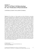
In order to test and verify the proposed model, TEM investigation of the Ni=La2 O3 catalyst was performed [37]: (i)
after reduction, (ii) after reaction under di erential conditions, (iii) after reaction under integral conditions and (iv)
after regeneration by calcination:
(i) On the reduced sample, rather large and faceted Ni
particles were observed (50 –100 nm), which give an average Ni dispersion around 1%, in agreement with the volumetric data. Each Ni particle is decorated by a continuous
layer of around 2 nm in thickness as can be seen on Fig. 8.
EDX analyses were carried out on the overlayer (a), on the
core of the particle (b), and on the support (c), as reported
in Table 4.
The overlayer which decorates the Ni particles was unambiguously found to contain a signiÿcant amount of lanthanum atoms, with the relative amount of La increasing
when decreasing the EDX spot size. Indeed, the smallest
EDX spot size (5 × 5 nm) being at least 2 times larger than
the overlayer (2 nm in thickness), a part of the nickel particle is necessarily included in the analysed area which explains the large contribution of Ni in the analysis (Table 4).
As seen in Fig. 8A(a), lattice planes of the overlayer are
visualized and the crystallographic parameters of this layer,
though not easy to measure, are consistent with a lanthanum
carbonate structure.
(ii) After 5-min exposure on the reforming stream under
di erential conditions (conversion about 5%), the decoration of nickel particles is still observed, along with some
carbon deposits: veils and hollow ÿlaments, characteristic
of the forms of coke observed on nickel catalysts for CO2
reforming.
(iii) After 20 h exposure to the reforming stream, either
under di erential or integral conditions, most of the Ni particles and lanthana grains appear to be completely surrounded
by carbon, which hinders any precise analysis of bulk and
surface particles composition. However, the particles present
the same average size as the ones of the freshly reduced
sample, which discards any signiÿcant sintering e ect under reaction conditions. It is also observed that some nickel
particles have been extracted from the lanthana support by
growing ÿlaments, as depicted in Fig. 8B. The lanthanum
element is no more detected by EDX on the border of the
extracted particles.
(iv) After regeneration by calcination at 750◦ C, the catalyst presents a strongly sintered aspect with particles agglomerated together with an average size of around 300 –
400 nm (Fig. 8C). On this micrograph, EDX analysis reveals zones of pure nickel (a) and zones of mixed lanthanum
and nickel composition with two dominant La/Ni atomic ratios around 2 (b) and 1 (c). They probably correspond to
the local formation of nickel lanthanum oxides LaNiO3 and
La2 NiO4 as identiÿed by XRD. Zones of pure lanthana are
observed on other area of similar aspect.
X.E. Verykios / International Journal of Hydrogen Energy 28 (2003) 1045 – 1063
1055
Fig. 8. TEM pictures of Ni=La2 O3 : (A) after initial reduction; (B) after reforming reaction under di erential conditions at 750◦ C; (C) after
calcination/regeneration at 750◦ C.
Table 4
EDX analysis carried out on various spots of the reduced sample
Area of EDX
analysis
Location in
Fig. 2A
La/Ni atomic
ratio (%)
Centre of a particle
(10 × 10 nm)
Border of a particle
(10 × 10 nm)
Border of a particle
(5 × 5 nm)
Support area free of
particle (10 × 10 nm)
b
1/99
a
7/93
a
12/88
c
100/0
Thus, the HR-TEM study of the fresh and spent Ni=La2 O3
catalyst has provided convincing evidence that the geometric
model proposed, which involves decoration of the Ni particles by lanthanum oxycarbonate species is rather realistic.
6. In-situ and ex-situ surface analysis
6.1. FTIR study of the Ni=La2 O3 catalyst
Fig. 9 shows the spectra obtained over the Ni=La2 O3 catalyst at di erent periods of time on stream at 750◦ C. It is
observed that a number of strong bands and weak bands ap-
Fig. 9. FTIR spectra over the Ni=La2 O3 catalyst after CH4 =CO2
reaction for various periods of time on stream at 750◦ C: (a) 0:5 h;
(b) 2 h; (c) 5 h.
1056
X.E. Verykios / International Journal of Hydrogen Energy 28 (2003) 1045 – 1063
Fig. 10. FTIR spectra over pure La2 O3 after exposure to (a) CO2 for 2 h and (b) the CH4 =CO2 mixture for 5 h at 750◦ C.
pear following reaction of CH4 =CO2 at 750◦ C. The bands
at 3608 and 3454 cm−1 correspond to the OH− groups
bounded in linear and bridged forms, respectively. As can
be derived from the spectra, these species ÿrst increase and
then decrease with increasing reaction time. This can be understood as follows: The surface of the Ni=La2 O3 catalyst
is enriched with H-containing species in the form of OH−
groups upon exposure to the CH4 =CO2 mixture at 750◦ C
compared to the fresh surface (see Fig. 9(a)). As the reaction
proceeds (i.e., time on stream longer than 2 h), the surface
OH− groups are gradually converted and the Ni=La2 O3 surface becomes H-deÿcient, containing even less surface OH−
groups than those on the fresh Ni=La2 O3 catalyst (spectra b
and c of Fig. 9). Besides the two OH− bands at 3454 and
3608 cm−1 , at least another nine bands exist, whose intensities change with time on stream. The two major bands at
1512 and 1371 cm−1 , observed after 30 min of reaction at
750◦ C (Fig. 9(a)), can be reasonably assigned to the formate
species on the La2 O3 support [48]. This is in harmony with
the observation of the band at ca. 2879 cm−1 , which should
be attributed to the stretching vibration of the C–H bond in
the HCOO− formate species. As the reaction time increases,
the bands at 1512 and 1371 cm−1 are gradually reduced,
while a sharp band at ca. 1315 cm−1 and a broad and intense
band at ca. 1550 cm−1 develop. A band at ca. 1464 cm−1 is
discernible at the shoulder of the band at 1550 cm−1 . Simultaneously, the intensities of the bands at 2879, 2502, 1834,
1754, 1088, 858, and 746 cm−1 increase continuously (Fig.
9(a) – (c)). Based on previous studies [49,50] as well as on
the results given in Fig. 10, the bands at 1834, 1754, 1550,
1464, 1088, 858, and 746 cm−1 can be attributed to the
La2 O2 CO3 species, which should be the result of the reaction between the La2 O3 support and CO2 . Among these, the
bands at 1550, 1464, 1089, 857, and 746 cm−1 are related to
the carbonate groups positioned between the (LaO)2+
2 layers,
while the weak bands at 1753 and 1835 cm−1 correspond
to the ¿ CKO group of the La2 O2 CO3 species. The band
at ca. 2500 cm−1 may be the result of overtones of several
vibrating groups. The increase of the band at 2879 cm−1
with increasing reaction time appears not to conform to the
reduction of the formate bands at 1512 and 1371 cm−1 . This
could be explained by reduction of the formate species on
the La2 O3 oxide and development of another type of formate species, presumably on the La2 O2 CO3 . The development of the band at ca. 1315 cm−1 could be the symmetric
stretching of this formate species. The band due to asymmetric stretching of the formate species should be hidden in
the broad band at ca. 1550 cm−1 (Fig. 9(c)). In conclusion,
X.E. Verykios / International Journal of Hydrogen Energy 28 (2003) 1045 – 1063
exposure of the Ni=La2 O3 catalyst to the CH4 =CO2 mixture
at 750◦ C, initially results in formation of OH− groups and
formate species on the Ni=La2 O3 catalyst, presumably on
the La2 O3 support. As the reaction time proceeds, the La2 O3
is gradually transformed into La2 O2 CO3 while the surface
OH− groups and formate species on the La2 O3 are simultaneously reduced. Meanwhile, “formate-type” species gradually accumulate on the La2 O2 CO3 phase.
Fig. 10 shows the spectra obtained over pure La2 O3 after exposure to CO2 and CH4 =CO2 at 750◦ C. It is shown
that, similar to the situation observed over the Ni=La2 O3
exposed to CH4 =CO2 mixture at 750◦ C, the groups of the
La2 O2 CO3 bands are also detected over La2 O3 after exposure to CO2 at 750◦ C for 2 h (Fig. 10(a)). This suggests
that La2 O3 is transformed into La2 O2 CO3 by reacting with
gaseous CO2 at high temperatures. In this case, four bands
at 1550, 1510, 1452, and 1315 cm−1 are observed in the
range 1300 –1600 cm−1 . As described above, the bands at
1550 and 1452 cm−1 are attributed to the carbonate species
of La2 O2 CO3 , while the bands at 1510 and 1315 cm−1 are
due to asymmetric and symmetric stretching of the formate species on the surface of La2 O2 CO3 . The band at ca.
2883 cm−1 corresponds to the C–H bond of this formate
species. The H source for formation of the surface species
should come from the surface OH− group on the La2 O3
support, as shown by the development of the negative bands
at 3609 and 3450 cm−1 . It is rather unexpected that two
bands, at 2171 and 2082 cm−1 , which correspond to two
types of linearly bound adsorbed CO species, are observed
on La2 O3 (Fig. 10(a)). Their formation appears to be associated with cleavage of the C–O bond of CO2 via participation of surface defects of La2 O3 or the reverse water–gas
shift reaction with involvement of the H-containing species
of the support. A similar spectrum was also obtained over
Ni=La2 O3 exposed to CO2 at 750◦ C. The fact that no adsorbed CO band is observed on the Ni=La2 O3 catalyst after
exposure to a CH4 =CO2 mixture from which CO and H2
are produced implies that the surface chemistry occurring
on the working Ni=La2 O3 catalyst (CH4 =CO2 reaction) may
be di erent from that on La2 O3 when interacting with CO2 ,
although some similar species exist on both surfaces. After
exposure of La2 O3 , to CH4 =CO2 at 750◦ C for 5 h, a very
di erent situation develops (Fig. 10(b)). Two strong negative bands at 3609 and 3450 cm−1 are observed, suggesting
that the surface becomes H-deÿcient compared to that of the
fresh La2 O3 . Besides these two negative bands, only two
small bands at 1581 and 1444 cm−1 are observed, which
may correspond to formate and/or carbonate species on the
La2 O3 surface. The group of bands due to the La2 O2 CO3
species is absent from the La2 O3 surface after exposure to
CH4 =CO2 at 750◦ C. This means that the presence of CH4
inhibits, whereas the presence of Ni promotes, the formation of the La2 O2 CO3 species (Figs. 9 and 10). Apparently,
the formation of the La2 O2 CO3 species, resulting from reaction between La2 O3 and CO2 , is signiÿcantly a ected by
the surrounding atmosphere.
1057
6.2. XPS study
The elemental composition of the Ni=La2 O3 catalyst after various treatments, i.e., reduced but not exposed to the
reactant mixture, exposed to the reactant mixture under differential conditions, and exposed to the reactant mixture
under integral conditions, was investigated by XPS, and the
results are presented below.
(a) Reduced catalysts. The data for a Ni=La2 O3 catalyst, reduced but not exposed to the reactant mixture, are
shown in Table 5. The interpretation of the XPS signals is
complicated for the lanthanum catalyst because ÿrstly the
lanthanum cross section varies considerably with the compound and, secondly, the particular lanthanum compound
that is present on the catalyst surface is unknown. The FTIR
results suggest La2 O2 CO3 , but the IR signal emanates from
a region up to ca. 0:5 m thick. The composition of the ca.
4 nm region probed by XPS may di er signiÿcantly.
Considering the carbon signal, Table 5 and Fig. 11(a), it
is evident that part of the carbon is present as carbonate.
Deconvolution of the C 1s signal gives a dominant peak with
fc = 0:54, where fc = fraction of carbon signal, and components at 1:4 eV(fc = 0:28) and 4:7 eV(fc = 0:18) higher
binding energy (BE), respectively. The signal at 1:4 eV
would correspond to the –CO–C– species, i.e., the carbon
overlayer is partly oxidized. The D4:7 eV component is
CO2−
3 and would be associated with the lanthanum. By translation of the intensities of the carbon species into a corresponding amount of oxygen, there are ca. 24 at% oxygen
as CO2−
and 12 at% as –CO–C–, i.e., a total of 36 at%
3
compared to the measured value of 50 at%. The oxygen
corresponding to the di erence in these amounts would be
the oxide/hydroxide species. The cross section of the La 3d
signal is given a nominal value of 10, which makes the lanthanum concentration 5 at%. The ratio of CO2−
3 : La (8:5)
does not correspond to La2 O2 CO3 and indicates an excess of
carbonate at the surface, if the La cross section is accurate.
The nickel content, at 3 at%, is close to the value for
the lanthanum support, suggesting that the nickel dispersion
on La2 O3 is large, contrary to the results of the hydrogen
chemisorption. However, the low La:C compared to the Al:C
XPS ratio shows that the Ni=La2 O3 catalyst is covered by
a carbonaceous overlayer. The H2 chemisorption and XPS
results can then be reconciled if the overlayer deposits preferentially on bare lanthanum support, leaving the metal free.
(b) Working catalysts/di erential conditions. Table 5
gives the elemental compositions for the catalyst after 5 h
of reaction at 750◦ C under di erential conditions. The
Ni=La2 O3 catalyst gained carbon during exposure to the
reaction mixture under di erential conditions. The C 1s
envelope, Fig. 11(b), showed a broad dominant signal with
a distant carbonate contribution at 4:7 eV higher BE. Deconvolution of the spectrum, using peaks of fwhh = 2:3 eV,
resolved the dominant signal into two main components, corresponding to –C–C– (fc = 0:61) and –CO–C– (fc = 0:24)
at 1:3 eV higher BE. A slight asymmetry at low BE
1058
X.E. Verykios / International Journal of Hydrogen Energy 28 (2003) 1045 – 1063
Table 5
Surface composition of the Ni=La2 O3 catalyst from XPS signals
Catalyst with
17 wt% Ni
Treatmenta
La2 O3
La2 O3
La2 O3
Reduced
Di erential
Integral
Surface concentration (at%)
C
Ni
La
O
42
63
83
3
2
1.5
5
2
1.3
50
33
15
a Reduced:
catalyst was reduced in H2 ow at 750◦ C for 1 h but not exposed to the reactant mixture. Di erential: catalyst was exposed
to di erential reaction conditions for 5 h (T = 750◦ C; Ftot = 300 ml=min; mat = 10 mg; CH4 =CO2 =He = 20=20=60 vol%, XCH4 ¡ 10%).
Integral: catalyst was exposed to integral reaction conditions: (T = 750◦ C; Ftot = 100 ml=min; mat = 30 mg; CH4 =CO2 =He = 20=20=60
vol%, XCH4 ¡ 70–80%).
required addition of a further peak (fc = 0:04) of unknown
origin. The carbonate contribution (fc = 0:12) corresponds
to 0:12 × 63 = 7 at%, and the fraction of carbonate stayed
approximately constant if the deconvolution peak width
was altered, but the –CO–C–:–C–C– ratio varied markedly
with fwhh.
The lanthanum signal is decreased compared to the
reduced catalyst in accordance with the increase in the
carbonaceous overlayer. Again, the CO2−
3 :La ratio (7:2)
indicates an excess of carbonate at the surface above
that expected for La2 O2 CO3 . The oxygen associated with
CO2−
and –CO–C– amounts to 37 at%, which is compa3
rable to the total measured oxygen content of 33 at%, i.e.,
oxide/hydroxide species do not appear to be signiÿcant.
(c) Working catalysts/integral conditions. Table 5 gives
the elemental compositions for the catalyst after 5 h exposure to the reactant mixture at 750◦ C under integral conditions. The Ni=La2 O3 catalyst has increased carbonaceous
overlayer under integral compared to that under di erential
conditions. The C 1s envelope, Fig. 11(c), consists mainly
of one component (fc = 0:87) that can be ÿtted by a peak
of fwhh = 2:0 eV. The tail on the curve can be ÿtted by
a – ∗ satellite at 7:0 eV and two components at ca. 2.8
(fc = 0:05) and 4:7 (fc = 0:02) eV above the main peak.
From the BEs, the latter would correspond to –COO– and
CO2−
3 , respectively. The total oxygen associated with the
carbon is equivalent to 13 at%. Nickel and lanthanum can
be detected by XPS at low levels, and the oxygen associated with the high BE carbon components does not exceed
the measured amount, 15 at%.
A signiÿcant amount of carbon species containing C–O
and C–H bonds, i.e., La2 O2 CO3 and formate species, are
observed by FTIR on the Ni=La2 O3 catalyst (Fig. 9). This is
in harmony with the XPS results, which reveal the presence
of a signiÿcant fraction of oxidized surface carbon, along
with –C–C– species, on the Ni=La2 O3 catalyst. Although
signiÿcant amounts of La2 O2 CO3 and formate species are
also formed on the pure (unmetalized) La2 O3 surface upon
exposure to CO2 , only small amounts of formate and/or carbonate species are formed on the pure La2 O3 surface upon
exposure to CH4 =CO2 at reaction temperatures (Fig. 10).
Apparently, both Ni and La2 O3 are contributing to formation of the –C–C– and oxidized carbon (i.e., La2 O2 CO3 and
formate) species, and these two types of carbon species are
distributed on di erent sites of the Ni=La2 O3 , i.e., the former
one on Ni crystallites and the latter one on La2 O3 support.
In the Ni=La2 O3 catalyst after 5 h under integral reaction conditions, the major XPS feature is a –C–C– deposit
which, from the – ∗ satellite and the narrow fwhh, may be
considered graphitic and conducting. The carbonate contribution is expected from the lanthana content. The remaining component corresponds to –COO–, which would agree
with the formate species detected by FTIR. Under di erential conditions, the carbonaceous deposit on the Ni=La2 O3 is
thinner, the – ∗ satellite is not discernible from the noise,
and the fwhh of the deconvolution peak is greater, i.e., the
overlayer appears to be less conducting. A carbonate signal
is observed, but the remaining carbon–oxygen species corresponds to –CO–C–. There was uncertainty concerning the
magnitude and position of the latter component although the
values taken did give an agreement with the oxygen content
deduced from the carbon deconvolution and the measured
value. The substantial carbon overlayer on the reduced but
unreacted Ni=La2 O3 catalyst also consisted of –C–C–, –CO–
C–, and CO2−
3 species, and consideration of the above data
in relation to the progression in exposure to reactants suggests that either a –COO– species is generated from the –
CO–C– component or the –CO–C– is displaced by –COO–
in the course of the reaction. This alteration is accompanied
by changes in the conductivity of the overlayer.
6.3. Correlation between surface composition and
catalytic performance
The catalytic performance of the Ni=La2 O3 catalyst differs substantially from that of Ni=Al2 O3 catalysts under conditions of CH4 reforming with CO2 . The rate of reaction
over the Ni=La2 O3 catalyst increases signiÿcantly with time
of reaction during the initial 2–5 h of reaction and subsequently tends to be essentially constant with time on stream,
exhibiting excellent stability (Fig. 1). The reverse trend is
observed (i.e., the rate exhibits continuous deactivation with
X.E. Verykios / International Journal of Hydrogen Energy 28 (2003) 1045 – 1063
1059
time on stream) when Ni=Al2 O3 catalysts are applied. For the
Ni=Al2 O3 catalysts, the continuous deactivation with time
on stream is attributed to accumulation of carbon species on
the surface, which gradually block the reaction sites.
The increase of reaction rate over the Ni=La2 O3 catalyst
during the initial 2–5 h of reaction is accompanied by a signiÿcant change of bulk and/or surface structure. It is shown
by the FTIR studies (Fig. 9) that the increase of reaction
rate during the initial 2–5 h of reaction is well correlated
with increasing concentration of the La2 O2 CO3 species and
formate-type species. It seems that the presence of a high
concentration of oxidized carbon, presumably La2 CO2 CO3
and formate-type species on the support in the Ni=La2 O3
catalyst, plays an important role in enhancing reaction rate.
It should be mentioned that, unlike the carbonate on strong
basic oxides, i.e., alkali and alkaline earth oxides, the carbonate species (in the form of La2 O2 CO3 ) on La2 O3 (of
a moderate basicity) only have moderate stability and tend
to be mobile and partially decomposed at the temperatures
applied for the reforming reaction [51,52]. Isotopic experiments have also conÿrmed that a large amount of atomic
oxygen species, originating from La2 O2 CO3 , participate in
CO formation in the CH4 =CO2 reaction. Thus, the oxycarbonate on the La2 O3 support might be considered a dynamic
oxygen pool. The increasing rate during the initial hours of
reaction could then be the result of enhanced reactions between surface carbon species and the increasing concentration of the oxygen pool (Fig. 9). The possible mechanism
for these reactions will be discussed in a subsequent section.
When the stable performance is obtained over the
Ni=La2 O3 catalyst, following 2–5 h of time on stream,
the surface carbon-containing species reach their steady or
pseudo-steady state. The FTIR and XPS results reveal that
the working Ni=La2 O3 catalyst contains La2 O2 CO3 and formate species, as well as –C–C– species on the surface. The
presence of a large amount of oxygen-containing surface
carbon should, in a certain way, favour the removal of the
–C–C– species as gaseous CO via oxidation reactions. The
stable performance obtained over the Ni=La2 O3 can then be
explained by the equilibrium between rate of formation of
the carbon species on the Ni crystallites and rate of removal
of these species by oxidation reactions with participation of
La2 O2 CO3 and/or formate species. Such chemistry should
be originating from the Ni–La2 O3 interaction, mainly occurring at the Ni–La2 O3 interfacial area.
Fig. 11. (a) C 1s XPS spectra obtained over Ni=La2 O3 catalyst
that was reduced at 750◦ C in H2 ow for 1 h. (b) C 1s
XPS spectra obtained over Ni=La2 O3 catalyst that was exposed to the reactant mixture for 5h under di erential
conditions: T = 750◦ C, Ftot = 300 ml=min; mcat = 10 mg,
and CH4 =CO2 =He = 20=20=60 vol%. (c) C 1s XPS spectra obtained over Ni=La2 O3 catalyst that was exposed to
the reactant mixture for 5 h under integral conditions:
T = 750◦ C; Ftot = 100 ml=min; mcat = 30 mg, and CH4 =CO2 =
He = 20=20=60 vol%.
7. Kinetics and mechanism
7.1. Kinetic studies
The in uence of the partial pressures of CH4 and CO2
on the rate of CO2 reforming of methane was studied over
the Ni=La2 O3 catalyst at atmospheric pressure in the temperature range 650 –750◦ C, under di erential conditions.
The Ni=La2 O3 catalyst was activated as follows. It was
1060
X.E. Verykios / International Journal of Hydrogen Energy 28 (2003) 1045 – 1063
0.00035
PCO2 = 10kPa
0.0003
750˚C
4
RCH / mol/g s
0.00025
700˚C
0.0002
0.00015
650˚C
0.0001
5E-005
0
0
10
20
30
40
50
60
PCH / kPa
(a)
4
0.0002
750˚C
700˚C
0.0001
650˚C
4
RCH / mol/g s
0.00015
5E-005
0
0
(b)
10
20
30
40
50
60
PCO2 / kPa
Fig. 12. E ect of alteration of partial pressures of (a) CH4 and
(b) CO2 at constant PCO2 and PCH4 , respectively, on the reaction
rate over Ni=La2 O3 catalyst at 650◦ C, 700◦ C and 750◦ C. Solid
symbols: experimental results, solid lines: model prediction.
ÿrst exposed to pure H2 at 750◦ C for 2 h and then to
the CH4 =CO2 =He (10=10=80 vol%) mixture at 750◦ C. The
reforming reaction was followed for 5 h, until the catalyst
had reached the stable level. After this treatment, the variation of CH4 or CO2 partial pressure was conducted. A constant CH4 partial pressure of 10 kPa was used as the CO2
partial pressure was varied between 2 and 58 kPa, and a constant partial pressure of CO2 equal to 10 kPa was used when
the CH4 partial pressure was varied between 2 and 50 kPa.
The e ect of the variation of the methane partial pressure on
the rate of methane consumption is presented in Fig. 12(a).
It is shown that the reaction rate is strongly a ected by the
partial pressure of methane for CH4 partial pressures lower
than 20 kPa. Further increase of partial pressure of CH4 up
to 50 kPa, does not seem to a ect measurably the rate of
reaction. The alteration of the rate of methane consumption
with partial pressure of CO2 and reaction temperature, at a
constant methane partial pressure of 10 kPa, is shown in
Fig. 12(b). A very strong in uence is observed as the CO2
partial pressure is varied in the range 0 –10 kPa. However,
a stable performance is observed as the CO2 partial pressure is varied in the range 13–60 kPa. Comparison of Fig.
12(a) and (b) suggests that the reaction rate is more sensitive to CO2 partial pressure, than to CH4 partial pressure,
at low CO2 and CH4 partial pressures, respectively. This
result indicates that CO2 adsorption on the Ni=La2 O3 catalyst is stronger than that of CH4 , which can be attributed
to the stronger interaction of the CO2 molecule with the
La2 O3 support, due to the basic nature of La2 O3 . It has
been established that CO2 reacts with La2 O3 and produces
La2 O2 CO3 species, which play an important role in the kinetic mechanism and the stability of the Ni=La2 O3 catalyst.
The e ect of alteration of CH4 and CO2 partial pressures
at constant CO2 or CH4 partial pressures of 5, 15 and 20 kPa,
on the rate of reaction at 750◦ C is shown in Fig. 13 (a) and
(b). It is apparent that a strong in uence of both reactants
on the reaction rate is observed at low CH4 and CO2 partial
pressures. The in uence becomes stronger as the concentration of CO2 or CH4 , respectively, in the reaction mixture
increases.
Fig. 14 demonstrates the alteration of the rates of CH4
and CO2 consumption as well as the rate of CO production
with variation of H2 partial pressure, as the CH4 and CO2
partial pressures were kept constant at 10 kPa, at the reaction temperature of 750◦ C. It can be observed that H2 has
essentially no e ect on the reforming activity of the Ni catalyst, as evidenced by the invariance of the rate of methane
consumption, with H2 partial pressure. The rates of CO formation and of CO2 consumption, on the other hand, increase
considerably with increase of hydrogen pressure. This result
can be attributed to the occurrence of the inverse water–gas
shift reaction. Thus, increase of H2 partial pressure leads to
a further CO2 consumption via the reaction
CO2 + H2 → CO + H2 O
which occurs in parallel with the CO2 reforming of CH4
reaction.
In addition, the in uence of CO partial pressure on the
reaction rate was studied in the temperature range 650 –
750◦ C. It was found that the rate of reforming reaction was
slightly in uenced by the partial pressure of CO, decreasing
with increasing PCO up to 4 kPa, and remained more or less
stable for further increases of PCO .
7.2. Reaction mechanism
The mechanism of the methane reforming reaction with
CO2 , over the Ni=La2 O3 catalyst has been investigated
employing a number of di erent techniques and the most
X.E. Verykios / International Journal of Hydrogen Energy 28 (2003) 1045 – 1063
0.00035
1061
12
PCO2 (kPa)
750˚C
750˚C
20
0.0003
RCO
15
9
R*104 / mol/g s
4
RCH / mol/g s
0.00025
5
0.0002
0.00015
0.0001
RCO2
6
3
5E-005
RCH4
0
0
10
20
30
40
50
PCH / kPa
(a)
0
4
0
2.5
5
7.5
10
12.5
PH / kPa
2
750˚C
PCH4 (kPa)
0.0003
Fig. 14. E ect of hydrogen partial pressure on the rates of methane
and CO2 consumption and CO production at 750◦ C.
20
0.0002
•
4
RCH / mol/g s
15
5
0.0001
•
0
0
(b)
10
20
30
40
50
60
PCO2 / kPa
Fig. 13. E ect of alteration of partial pressures of (a) CH4 and
(b) CO2 on the reaction rate over Ni=La2 O3 catalyst as the partial
pressures of CO2 and CH4 , respectively, are kept constant at 5,
15 and 20 kPa. Solid symbols: experimental results, solid lines:
model prediction.
important observations, upon which the proposed mechanism is based, are the following:
• A certain fraction of the Ni content of the catalyst is visible
by XPS and SIMS, following the reforming reaction even
under integral conditions. This implies that portion of Ni
is free of carbon deposits under reaction conditions [34].
• Methane was detected (by steady-state isotopic tracing
kinetic analysis) to exist on the surface of the catalyst
under reaction conditions [38].
• Transient studies have shown that the rate of dissociation
of CO2 on Ni crystallites is not signiÿcant as compared to
•
•
•
that of CH4 . Naturally, the carbon which accumulates onto
Ni crystallites, derives mostly from the CH4 molecule
[39].
A strong interaction exists between CO2 and the La2 O3
support leading to the formation of stable La2 O2 CO3
species, which are detected by FTIR and XRD [35].
Transient studies employing isotopically labeled
molecules indicate that the La2 O3 support or the
La2 O2 CO3 species which are formed behave as a dynamic
oxygen pool under reaction conditions, participating in
the formation of CO [38].
In contrast to the Ni=Al2 O3 catalyst, over the Ni=La2 O3
catalyst, cracking of methane on Ni is a slow step [36].
The active carbon-containing species which exist on the
catalyst surface under reaction conditions consist exclusively of carbon, and not of CHx ; x ¿ 0, species [39].
HR-TEM has revealed that islands of La2 O3 exist on the
surface of the Ni particles under reaction conditions. This
structure is probably formed during preparation of the
catalyst [37].
Based on these observations, the following mechanistic
steps, which lead to the production of CO and H2 are proposed:
1. Reversible adsorption of methane on the surface of Ni
which leads to cracking of methane and production of
carbon deposits and hydrogen. Methane cracking is a
slow step while methane adsorption is at equilibrium:
CH4 + S
k
K1
S–CH4 ;
2
+ 2H;
S–CH4 →S–C
equilibrium;
(1)
RDS;
(2)
1062
X.E. Verykios / International Journal of Hydrogen Energy 28 (2003) 1045 – 1063
2. A strong interaction exists between CO2 and La2 O3
which leads to the formation of La2 O2 CO3 species. This
is a fast step, considered to be at equilibrium
CO2 + La2 O3
K3
La2 O2 CO3 ;
equilibrium:
(3)
3. La2 O2 CO3 species react with carbon deposited onto Ni
particles at the interface between Ni and La2 O2 CO3 . In
this way the methane cracking activity of Ni (at the periphery of the La2 O2 CO3 particles) is restored and the
catalyst exhibits good stability. Therefore, the active portion of the catalyst is the interfacial area between Ni and
oxycarbonate particles. The remaining surface of Ni is
covered by carbon deposits. This step is also considered
to be a slow step in the sequence
k
4
La2 O2 CO3 + C–S→
La2 O3 + 2CO + S;
RDS:
(4)
4. Adsorbed hydrogen, at very low surface coverage, may
also exist and interact with other surface species. This
adsorbed hydrogen originates from the sequential cracking of the methane molecule and it is assumed to be at
equilibrium with gas phase hydrogen
H2 + 2S
2S–H;
equilibrium:
(5)
The following steps are assumed to be fast steps in comparison withslow steps 2 and 4 above:
La2 O3 + CO + S–OH− ;
La2 O2 CO3 + H–S
S–OH− + C–S
(7)
H2 O + 2S;
S–OH + S–H
S-CO
S–CO + S–H(s);
(6)
(8a)
CO + S:
(9)
1. Simultaneously, the inverse water–gas shift reaction takes
place, which may be described by the following sequence
of reaction steps:
CO2 + S
S–CO2 ;
S–CO2 + H–S
S–OH + H–S
S–CO + OH–S;
H2 O + 2S:
(10)
slow;
(11)
(8b)
either covered with carbon or it is vacant. Alternatively, it
is assumed that the surface coverage of other species, such
as H or CO, is negligible. Under these assumptions, the rate
of methane conversion is of the form
RCH4 =
K1 k2 K3 k4 PCH4 PCO2
K1 k2 K3 PCH4 PCO2 + K1 k2 PCH4 + K3 k4 PCO2
(12)
where K1 is the equilibrium constant of methane adsorption and k2 the rate constant of the decomposition (cracking) of methane on the surface of Ni.
The two constants could not be determined individually but only their product which was found to be:
K1 k2 = 2:61 × 10−3 exp(−4300=T ) (mol=g s)(kPa)−1 . The
value of −4300 represents the sum of the activation energy of methane cracking and the enthalpy of methane
adsorption on Ni. The constant K3 which is the equilibrium
constant of the reaction between CO2 and La2 O3 was found
to be 5:17 × 10−5 exp(8700=T ) (kPa)−1 while the rate constant of the reaction between the oxycarbonate species and
carbon deposited on the surface of Ni, k4 , was found to be
5:35 × 10−1 exp(−7500=T ) (mol=g s).
The predictions of the model, i.e. the rate of methane consumption as a function of CH4 and CO2 partial pressures and
temperature are shown in Figs. 12 and 13. In Fig. 12(a), the
experimental results (symbols) along with the model predictions (solid lines) are shown for the experiment in which
the methane partial pressure was varied at a constant CO2
partial pressure of 10 kPa, within the temperature range 650
–750◦ C. In Fig. 12(b), the experimental results (symbols),
along with the model predictions (solid lines), are shown for
the experiment in which the CO2 partial pressure was varied
at a constant CH4 partial pressure of 10 kPa within the same
temperature range. It can be seen that in both cases, the ÿtting
obtained by the model is very good and the main features of
the reaction are adequately described. In Fig. 13(a) the experimental data and the model predictions are presented for
the cases which the partial pressure of CO2 is constant at 5,
15 and 20 kPa while the partial pressure of CH4 is varied.
Similarly, in Fig. 13(b) the experimental data and model
predictions are presented for the cases in which the partial
pressure of CH4 is constant at 5, 15 and 20 kPa, while PCO2
is varied. It is obvious that the kinetic model predicts satisfactorily the kinetic results. The success of the prediction
of the kinetic data by the model is not fortuitous. No other
kinetic model, among those which were tested could predict
satisfactorily the kinetic results. The good model prediction
is due to the fact that the development of the kinetic model
is based on detailed mechanistic studies.
7.3. Kinetic model
A rate expression for the CO2 reforming of methane is developed, based on the mechanism illustrated above, assuming that steps 2 and 4 are both rate-controlling. It is further
assumed that the Ni surface at the periphery of the oxycarbonate particles, which is the catalytically active surface, is
8. Summary
In contrast to most Ni-based catalysts, the Ni=La2 O3 catalyst exhibits a remarkably stable performance under conditions of dry reforming of methane, even at relatively low
X.E. Verykios / International Journal of Hydrogen Energy 28 (2003) 1045 – 1063
temperatures. The structure of this catalyst, before and after
exposure to reaction conditions, was investigated employing
various techniques, such as XRD, H2 and CO chemisorption,
XPS, FTIR and HR-TEM. The results indicate that the Ni
surface is partially covered by La2 O2 CO3 species, which
originate by reaction between La2 O3 species and CO2 , while
the catalytic chemistry is occurring at the Ni–La2 O2 CO3
interfacial area. It is proposed that although CH4 cracks on
the Ni crystallites, CO2 favourably adsorbs on the La2 O3
support and lanthanum—containing species which decorate
the Ni particles, in the form of La2 O2 CO3 . The reaction
between the carbon species formed upon cracking of CH4 on
Ni crystallites and the ”oxidant” originating from the support
side, which can be the La2 O2 CO3 species, constitutes the
new chemistry occurring at the Ni–La2 O3 interfacial area.
This o ers active and stable performance for carbon dioxide
reforming of methane to synthesis gas.
The kinetics of the reaction were also investigated in the
temperature range of 650 –750◦ C by variation of the partial pressures of the reactants. Based on mechanistic studies, a mechanistic model is proposed from which a kinetic
model is derived. The mechanistic scheme assumes adsorption and cracking of methane on Ni, followed by carbon
deposition, as a slow step, reaction of CO2 with La2 O3 to
form La2 O2 CO3 (fast step) and reaction of the oxycarbonates with carbon at the Ni–La2 O2 CO3 interface (slow step)
to produce CO. The inverse water–gas shift reaction occurs
simultaneously. The kinetic model which is based on the
mechanism predicts satisfactorily the kinetic results.
Acknowledgements
The author expresses his gratitude to Zhaolong Zhang,
Angelos Efstathiou and Vaso Tsipouriari for the long and
fruitful collaboration and to the Commission of the European
Union for ÿnancial support of this work.
References
[1] Trimm DL. Catal Rev-Sci Eng 1977;16:155.
[2] McCrary JH, McCrary GE, Chubb TA, Nemecek JJ, Simmons
DE. Sol Energy 1982;29:141.
[3] Tokunaga O, Osada Y, Ogasawara S. Fuel 1989;68:990.
[4] Fischer F, Tropsch H. Brennst Chem 1928;3:39.
[5] Tenner S. Hydrocarbon Process 1985;64:106.
[6] Sodesawa T, Dobaschi A, Nozaki F. React Kinet Catal Lett
1979;12:107.
[7] Schubb TA. Sol Energy 1980;24:341.
[8] Gadalla AM, Bower B. Chem Eng Sci 1988;43:3049.
[9] Rostrup-Nielsen JR. Stud Surf Sci Catal 1988;36:73.
[10] Gadalla AM, Sommer ME. Chem Eng Sci 1989;44:2825.
[11] Yamazaki O, Nozaki T, Omata K, Fujimoto K. Chem Lett
1992; 1953.
[12] Richardson JT, Paripatyadar SA. Appl Catal 1990;61:293.
1063
[13] Ashcroft AT, Cheetman AK, Green MLH, Vernon PDF.
Nature (London) 1991;352:225.
[14] Solymosi F, Kutsan G, Erdohelyi A. Catal Lett 1991;11:149.
[15] Erdohelyi A, Cserenyi J, Solymosi F. J Catal 1993;141:287.
[16] Rostrup-Nielsen JR, Back Hansen J-H. J Catal 1993;144:38.
[17] Erdohelyi A, Cserenyi J, Solymosi F. Appl Catal A
1994;108:205.
[18] Nakamura J, Akkawa K, Sato K, Uchijima T. J Jpn Pet Inst
1993;97:36.
[19] Nakamura J, Akkawa K, Sato K, Uchijima T. Catal Lett
1994;25:265.
[20] Tsipouriari VA, Efstathiou AM, Zhang ZL, Verykios XE.
Catal Today 1994;21:579.
[21] Zhang ZL, Tsipouriari VA, Efstathiou AM, Verykios XE.
J Catal 1996;158:51.
[22] Efstathiou AM, Kladi A, Tsipouriari VA, Verykios XE.
J Catal 1996;158:64.
[23] Rudnitskii LA, Solboleva TN, Alekseev AM. React Kinet
Catal Lett 1984;26:149.
[24] Arakawa T, Oka M, F.P. Patent No. 2228102.
[25] Arakawa T, Oka M. NL Patent No. 7302403.
[26] Arakawa T, Oka M. US Patent No. 3849087.
[27] Arakawa T, Oka M. DE Patent No. 2308161.
[28] Zhang ZL, Verykios XE. Catal Today 1994;21:589.
[29] Rostrup-Nielsen JR. J Catal 1984;85:31.
[30] Rostrup-Nielsen JR. Stud Surf Sci Catal 1991;68:85.
[31] Rostrup-Nielsen JR. Natural gas conversion II. In: Curry-Hyde
HE, Howe RF, editors. Lausanne, Switzerland: Elsevier, 1994.
p. 25.
[32] Swaan HM, Kroll VCH, Martin GA, Mirodatos C. Catal Today
1994;21:571.
[33] Zhang ZL, Verykios XE. J Chem Soc Chem Commun 1995;
71.
[34] Zhang ZL, Verykios XE, MacDonald SM, A orssmann S.
J Phys Chem 1996;100:744.
[35] Zhang ZL, Verykios XE. Appl Catal A 1996;138:109.
[36] Zhang ZL, Verykios XE. Catal Lett 1996;38:175.
[37] Slagtern A, Schuurman Y, Leclercq C, Verykios X, Mirodatos
C. J Catal 1997;172:118.
[38] Tsipouriari VA, Verykios XE. J Catal 1999;187:85.
[39] Tsipouriari VA, Verykios XE. Catal Today 2001;54:83.
[40] Ridler DE, Twigg MV. In: Twigg MV, editor. Catalyst
handbook. London: Wolfe, 1989. p. 225.
[41] Bartholomew CH, Pannell RB. J Catal 1980;65:390.
[42] Bartholomew CH, Pannell RB, Butler JL. J Catal 1980;65:335.
[43] Paal Z, Menon PG. Catal Rev-Sci Eng 1983;25:229.
[44] Kalenik Z, Wolf EE. Catal Lett 1991;9:441.
[45] Kalenik Z, Wolf EE. Catal Lett 1991;11:309.
[46] Kuijpers EGM, Breedijk AK, van der Wal WJJ, Geus JW.
J Catal 1981;72:210.
[47] Cambell RA, Szanyi J, Lenz P, Goodman DW. Catal Lett
1993;17:39.
[48] Burkett HD, Worley S, Dai CH. Chem Phys Lett
1990;173:430.
[49] turiotte RP, Sawyer JO, Eying L. Inorg Chem 1969;8:238.
[50] Taylor RP, Schrader GL. Ind Eng Chem Res 1991;30:1016.
[51] Bernal S, Martin GA, Morl P, Perrichon V. Catal Lett
1990;6:231.
[52] Krylov OV, Kh Mamedov A, Mirzabekova SR. Ind Eng Chem
Res 1995;34:474.