Tai lieu xu ly corona HT
Bạn đang xem bản rút gọn của tài liệu. Xem và tải ngay bản đầy đủ của tài liệu tại đây (5.11 MB, 9 trang )
8
GE Energy
Engineering Laboratory, Peterborough, Ontario, ClJIIada
Technical Report 2005-BG-13; version 2c
Repair Procedure to Suppress PD Activity
Between Top and Bottom Stator Bars
in the Winding of Generators #1 and 2
at Ham Thuan Power Generation Station
Author:
BogdanGronowski,EngineeringLaboratory,GE Hydro,Peterborough,ON
Distribution:
Ian McIntyre, GE Energy, Peterborough, ON
Don McLaren, GE Energy, Peterborough, ON
Rob Draper, GE Energy, Peterborough, ON
Bassem Kamel, GE Energy, Peterborough, ON
Bruce Mills, GE Energy, Peterborough, ON
Patrick Cote, GE Energy, Lachine, QC
Jean-Yves Leclerc, GE Energy, Lachine, QC
June 29, 2005
- - - --
.
GE Energy
1.Subject
This procedure is intended for the suppression of partial discharge (PD) activity occurring between selected pairs of
top and bottom stator bars in the winding of generators 1 and 2 at Ham TIlUanPower Generation Station in Vietnam
and to repair damages to the external voltage grading system in the affected areas.
2. Background
As a result of a site inspection stator winding of generator # 1 and 2, the evidence of PD activity in air gaps between
selected pairs of top and bottom bars has been found. In order to eliminate this deficiency, it has been decided that
the air gaps between bars showing PD activity should be filled with solid insulating material.
3. General Overview
The intent of the repair is to effectively replace the air between the top and bottom bars of the affected slots with a
silicon material RTV 108 or RTV 102. There are two optional methods available for this operation. The fJfSt
method involves the placement of a pre-formed silicon pad lubricated with RTV 108 or RTV 102 to the air gap
between bars. The second option involves a direct injection of RTV 108 or RTV 102 to the air gap. The choice
between these two approaches depends on size of the affected air gap between the bars. Whichever the method is
selected, it is required to thoroughly clean the area to which the silicon material is going to be applied.
The choice of using preformed silicon pads or injection will be determined by the gap size between the suspect bars
and ability to stretch thicker silicon pads for insertion into the gap. Laboratory trials indicated that for air gaps
larger than 0.050 inch, the silicon injection method should be employed. For smaller than 0.050 inch air gaps, it is
better to use silicon pads lubricated with RTV 108 or RTV 102. However, the quoted air gap of 0.050 inch is not
critical and if there are silicon pads available in thicker sizes and the operator has the ability to stretch a given
silicon pad to be able insert it firmly into the air gap, the latter method can be preferably used. In general, by using
silicon pads better results can be achieved, specifically from the long-term performance point of view. It is a
consequence of the fact that probability of introducing voids, being a potential source of partial discharge, into the
affected air gaps is '!:mchlower while prefabricated silicon pads are used.
4. Tools and Material Checklist.
.
The followingmaterialsarerequired:
Gametsandpaper(280to 400grit);..y. .Gradingpaint #L7398;
. Brushes(-1.0 inchwide);
1 ~.
Siliconpadsmadeof silicon108or 102;
.v. .RTV 108 or 102 in 12 or 10 oz tubes;
1 ..y.
; .x .
SEMCO caulk Guns (for 12 oz tubes) or equivalent;
SEMCO nozzles (tips) preformed (bent) to the angle of 70 deg or-similar;
Environmentally compliant cleaning agent, preferably Acetone.
The SEMCO guns model # 850-12M and tubes are available from SEMCO LTD whose head office is located in
California. Our record indicate that the address is: 5454 San Fernando Road, Glendale, California, USA. 91203, tel.
(816) 247-7140.
---
--
---~
.
GE Energy
S. Corona Repair Procedure
Step 1: Sandin2
The surface of external grading system in the air gap between bars, which appear to be covered by whitish powdery
substance should be sanded using a 280 to 400 garnet sandpaper, to approximately 0.5 inches on each side of the
distress center, until the cleaned area is free from this substance. The attention should be paid to not remove too
much of the voltage grading paint and definitively not to affect the voltage grading tape under the paint. If the
external grading system is visibly damaged (e.g. scratched), the affected area should be sanded too to obtain a
smooth surface. The dust created during this process has to be removed, i.e. by a very good quality vacuum cleaner,
which captures all dust or using a piece of fabric wetted in acetone.
Step 2: Cleanin2 with Acetone
Step 1 should be followed by wiping the sanded surfaces by using rags dampened with an environmentally
compliant cleaning solution (e.g. Acetone). Do not use any other solvent, such as naphtha, which may leave a oily
residue, or Ketone type solvents that may attack the tape resin. The purpose of this step is to remove any residuals
in preparation for painting. In particular all areas with sanded cracks should be thoroughly cleaned with acetone to
remove any conductive substances from the cracks. Allow the cleaned surfaces to dry for a minimum of 30 minutes.
Step 3: Painting with L7398
Steps 1 and 2 should be repeated for several bars prior to beginning painting, since after opening a can containing
L7398 its contents should be preferably used within eight hours. Every time, before painting, the contents of the can
should be thoroughly mixed but no air bubble should be created during this process. The paint should be applied
using a new soft brush. If during the painting the consistency of the paint visibly changes (becomes dense) the paint
should be discarded. To minimize the effect of curing the paint in the can, the access of fresh air into the can should
be limited, for example by a lid. The painted area should appear smooth. Therefore, if the brush leaves paint marks,
the paint and brush should be discarded. Brush fibers shall not be left on the painted surface. After application, the
grading paint should be allowed to cure at room temperature for a minimum of six hours.
---
--
.
GE Energy
Step 4: Repair
Prior to the insertion or injection of silicon material the cleaned areas should be painted using Voltage Grading
Paint #L7398. Based on gap thickness, use one of the below described method A or B. The method A shall be
employed for air gaps below 50 mils. From the existing communication it appears that method A shall be attempted
fllSt.
Method A: Insertion Method Using Pre-Formed Silicon Pads
.
.
.
.
.
..
.
For the repair use silicon pads provided in several thickness.
Assess the size of the air gap between bars and choose a pad (in uncompressed stage) that is slightly thicker
(about 15-20%) than the size of the air gap.
Apply a thin layer of GE RTV 108 to both sides of silicon material in the centre area of the pad. This will serve
two purposes.
1. Act as slip plane during insertion,
2. Provide adhesion to bar surfaces once positioned.
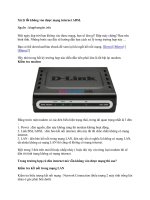
Position silicon pad between top and bottom bars above the first radius from core. See Figure 1. Firmly grip pad
by tightly pulling ends radially toward the bore on each side of the top bar. This will stretch material to allow
for positioning as the pad is maneuvered down (or up if working at the turbine end) between top and bottom
legs.
Once positioned, allow the stretched silicon pad to return to its normal stage by releasing the tension on
material. See Figure 2.
Ensure that there are no wrinkles on the inserted pad.
After curing the RTV for 24 hours, trim the silicon pads on both sides of bar arms. See Figure 3. Don't stretch
pad while trimming.
Apply RTV to ftll any gaps and cavities and smooth it to obtain a very smooth surface. See Figures 4 and 5.
Method B: Injecdon Method
.
.
.
InserttubeswithRTV 108or 102to SEMCOtubes.
.
Place the tip of the tube's nozzle to the air gap. See Figure 6.
Start injection from grading/conducting armour junction closest to the core with the intention of working
toward end-head location away from core.
Ensure that the RTV has passed through the air gap and that it is visible on opposite side before moving axially
.
Be careful not to create air cavities in the volume of the injected RTV while ftlling.
.
.
.
toward end-head location. See Figure 7.
TerminateRTVinjectionat fllStradiusof top andbottomleg.SeeFigure8.
Remove excess ofRTV to a flat surface with the edges of top and bottom bars. See Figure 9.
Adjust the speed of the insertion, specifically for the smaller gaps as they tend to oppose material flow and a
build up of silicon material on the dispensing side is to be expected.
Step 5: Inspecdon
..
.
Inspect the repaired areas for the adequate fill.
Eliminate all air cavities from the volume filled with silicon and groom to obtain the smooth surface as
necessary.
Photograph repaired areas for future reference. Send copies to the Engineering Laboratory.
.
GEEnergy
7. Photographic Record
Method
A:
-
-- -
.
-
~
.
Figure I: Stretch the band of silicon pad tight over end head (lubricated with RTV).
oWl
__
Figure 2: Slide the band into place while stretching.
--
---
--'-"--
.
GE Energy
Figure 3: Trim flush with bar face.
III
a
Iii
(;I
'*"
I
I:!
t;,
.-'
Figure 4: Fill with RTV to create a smooth surface.
---
-----
.
GE Energy
~~
Figure5: Tool RTV flushwith barface.
---
GEEnergy
Method
B:
r
(
I.
I
.
.
.p
Figure 6: Start injection.
,#
.-
Figure7: Injectuntil materialflows throughthe oppositeside before moving axially.
---
-----
.J
.
GE Energy
,~i
Figure 8: Final fill should look like this on the opposite injection side.
Figure 9: Tool while still wet