chon bom thap giai nhiet
Bạn đang xem bản rút gọn của tài liệu. Xem và tải ngay bản đầy đủ của tài liệu tại đây (4.38 MB, 46 trang )
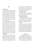
Cooling Tower Pumping and Piping
››Legend
This section
courtesy
of ITT Industries,
Inc.Industries,
©COPYRIGHT
2011 ITT INDUSTRIES,
INC.
Reprinted
with permission
from ITT
Inc. Copyright
2011.
Flow-Friction Loss
Automatic Valve
Balance Valve (Plug)
Condenser
Butterfly Valve
Heat Rejection Equipment
Automatic Butterfly Valve
Pump
Triple-Duty Valve
Valve
Pressure Reducing Valve
Node
Mixing/Diverting Valve
s
Non-Slam Check Valve
Strainer
Color Notes:
Cooling Tower
PRODUCT & APPLICATION HANDBOOK 2012
J121
T E CHNICAL RESOURCES
Cooling Tower Pumping and Piping
››Tower Pumping
Tower pumping does not present great difficulty in terms of good pump application. This is because of a normally high order of
application safety factor. Troubles do occur occasionally, however, and these troubles can be classified as caused by:
1. Incorrect pump head estimation.
2. Pump cavitation and loss of pumping ability, as caused by inadequate pump suction pressure.
3. Air in pump suction; as caused by tower pan vortex, pan drain down or faulty bypass.
4. Unstable pump operational points as caused by:
a. Improper application of tower bypass controls.
b. High pressure drop tower spray nozzles in combination with tower bypass.
5. Inadequate maintenance procedures causing:
a. Plugged suction strainer.
b. Lack of tower treatment with consequent fouling of the condenser.
It is intended that each potential trouble source be evaluated so that the necessary design safeguards can be erected against
operational problems.
Open “Tower” System Pump Head Requirements
The pumping head determination procedure for the “open”
tower piping loop differs from the conventional “closed”
loop piping circuit used for most Hydronic (Heat-Cool)
applications. The difference concerns consideration of
“open” loop static heads.
The closed loop circuit has no need for consideration of
static heads for pump selection because of a balance or
cancellation of static heads between the supply and return
risers. Static head lost by water flow to any height in the
supply piping is cancelled by a static head “regain” as
water flows down the return piping. The only pump head
requirement for the “closed” loop is that due to flow-friction
pressure drop; static heights are not considered.
Closed Loop
Piping Circuit
Figure 1. Static Height Not Considered for Pump Selection in
Closed Loop
J122
Q U E S T I O N S ? C A L L 4 1 0 . 7 9 9 . 6 2 0 0 O R V I S I T W W W. B A LT I M O R E A I R C O I L . C O M
Flow-Friction
Loss ∆h
The “open” or tower circuit is different from the “closed” loop circuit. The difference is that all static heads are not cancelable. In
the open piping circuit, the pump must raise fluid from a low reference level to a higher level; this requires pump work, and open
statics becomes an important consideration for pump selection.
In Figure 2, the required pump head will be the pipe flow-friction loss from A to D plus the energy head (Hs) required to raise water
from the lower to higher level.
D
Hs
Water Level
Pump Suction
Water Will
Reach This Level
Without Pump Energy
A
s
H
B
C
Figure 2. Open Piping Circuit
The cooling tower circuit differs slightly from the basic “open” circuit in that the discharge piping is connected directly to a
distribution basin. Some towers are furnished with a distribution manifold with nozzles which require additional pressure.
For the tower piping circuit, the pump must overcome the piping flow friction loss; piping, condenser, cooling tower losses, and
valves. It must also provide the energy head necessary to raise water from a low to a higher static head level.
Reprinted with permission from ITT Industries, Inc. Copyright 2011.
PRODUCT & APPLICATION HANDBOOK 2012
J123
T E CHNICAL RESOURCES
Cooling Tower Pumping and Piping
Most discussions concerning tower and/or open piping circuits would simply define the required pump static energy head as Ho
(in Figure 3); the “open” height of the piping circuit. This is, however, an ever-simplified assumption which may or may not be
true depending on whether or not a “siphon draw” is established in the downcomer return piping DE.
The nature of the downcomer siphon draw and its limitations should be evaluated.
D
Hr
E
Hs
Water Level
Pump Suction Side
Ho
Condenser
Dicharge Piping
A
H
B
Water Will
Reach This Level
Without Pump Work,
“H” Cancels
C
Figure 3. Typical “Open” Tower Piping Circuit
Downcomer Siphon Draw
In Figure 3, water is being discharged at E. Pressure at D must be equal to exit loss plus flow-friction loss DE and minus the
static pressure reduction caused by downcomer return static height Hr.
Pressure reduction to D as caused by static height Hr will generally, but not always, permit cancellation of height Hr as a part of
the required pump head. This is because of a resultant siphon draw action in the downcomer.
Given that the “siphon draw” does indeed occur, the required pump head will become:
PUMP HEAD in Figure 3 = H0 + ∆h (AE)
The pump head selection statement shown above is commonly accepted as a truism. It has limitations, however, and will not
apply under certain circumstances. These circumstances should be understood if unnecessary cost and embarrassment are to
be avoided by the consultant.
Exit loss and flow-friction loss in the downcomer will generally be less than the downcomer height Hr. For this circumstance the
downcomer must operate at subatmospheric pressure when the siphon draw is established. If the downcomer vacuum is broken,
the expected siphon draw will not occur and the estimated pump head may be inadequate.
J124
Q U E S T I O N S ? C A L L 4 1 0 . 7 9 9 . 6 2 0 0 O R V I S I T W W W. B A LT I M O R E A I R C O I L . C O M
The expected downcomer return siphon draw vacuum can be broken by any of three basic application circumstances:
•
Top vented downcomer.
•
Inadequate downcomer flow rates; bottom vented downcomer.
•
Fluid vapor pressure or flash considerations.
Top Vented Downcomer
A downcomer vent will break the siphon draw vacuum. The vent may be a simple loose pipe connection - or it may be a
mechanical vent purposefully applied at the downcomer return high point.
Vents are sometimes applied to establish known reference pumping conditions when downcomer return siphon draw conditions
propose stability problems; as with a very high downcomer, when fluid boiling is a probability or when start-up downcomer flow
rates are anticipated as inadequate for the siphon draw.
Given a top vented downcomer, it will be seen that the pump must raise water from the pump suction pan water level to the
highest vented point in the downcomer.
Considering this point to occur at D in Figure 3, the required pump static head will become:
Ho + Hr or Hs
The total pumping head to point D will become Hs plus the flow-friction loss ∆h (AD). Separate consideration must now be given
to the downcomer return.
Since the pump has raised water to level “D,” it will have provided a fluid head equal to Hr to overcome flow-friction loss in the
downcomer. There are two different pumping possibilities; fluid head Hr greater than downcomer flow-friction loss ∆h (DE) and
the reverse: Hr less than ∆h (DE).
The usual pumping circumstance will be the condition of Hr greater than ∆h (DE). This is because the available fluid head Hr
is the equivalent of 100 ft / 100 ft pipe friction loss rate. Downcomer piping flow-friction loss will generally be to the order of
4 ft /100 ft. Since the pump has already provided the necessary fluid head to flow the downcomer, Hr > ∆h (DE); friction flow
loss in the downcomer is not a part of the required pump head and total pump head becomes:
If: Hr > ∆h (DE)
Then: PUMP HEAD = Hs + ∆h (AD)
High downcomer pressure drops can be caused by control valves or tower spray nozzles. When this pressure drop plus the
downcomer pipe flow-friction loss exceeds fluid head Hr, the pump head must be increased by the difference ∆h (DE) minus Hr.
Total pump head then becomes:
If: ∆h (DE) > Hr
Then: PUMP HEAD = Hs + ∆h (AD) + [∆h (DE) – Hr ]
Reprinted with permission from ITT Industries, Inc. Copyright 2011.
PRODUCT & APPLICATION HANDBOOK 2012
J125
T E CHNICAL RESOURCES
Cooling Tower Pumping and Piping
Bottom Vented Downcomer; Inadequate Flow Rates
Downcomer flow rates can be so low, relative to pipe size, as to allow air to enter at the pipe discharge. This circumstance will
cause the downcomer to become vented and will prevent formation of the necessary siphon draw vacuum.
Tests conducted at ITT Bell & Gossett indicate that the siphon draw will not be established when the actual flow-friction loss
rate is less than the order of 1 ft /100 ft based on clean pipe pressure drop evaluation.
Pump head requirements for the bottom vented downcomer will be as previously noted for the top vented circumstance.
An unfortunate operational sequence can occur during pump start-up when the pump energy head is devoted towards simply
raising water from the low level pan to the highest part of the system.
During this start-up period, flow rates can be so low as to cause “bottom venting” and prevent (sometimes forever) formation
of siphon draw circumstances and full design flow rates. A water legged discharge or discharge reducer will provide automatic
siphon draw establishment so long as minimum “start-up” flow velocity in the downcomer is to the order of 1 ft/s.
In Figure 4, air entry into the pipe discharge is prevented. The minimum flow velocity pulls air bubbles down the piping, finally
evacuating the downcomer of air and establishing the siphon draw condition; downcomer pipe full of water and operating at
subatmospheric pressure.
Unusual application circumstances will sometimes establish such a low start-up flow rate (less than 1 ft/s velocity) that air
bubbles are not carried down the piping. The downcomer cannot then be emptied of air and expected siphon draw will never
occur.
Oversized Downcomers
(Minimum Velocity 1ft/s)
Water Leg
Splash Pan
Reducer One Pipe Size
or Valve
Splash Pan
Figure 4. Water Leg or Reducer Help Establish Siphon Draw in Downcomer on Start-Up
J126
Q U E S T I O N S ? C A L L 4 1 0 . 7 9 9 . 6 2 0 0 O R V I S I T W W W. B A LT I M O R E A I R C O I L . C O M
Vent
Downcomer
For this circumstance it is necessary to
separately fill the downcomer with water.
This can be accomplished by valve closure
at the piping exit in combination with a
top vent. During start-up, the exit valve
is closed and the vent opened. After the
piping is filled, the vent is closed and the
exit valve opened.
Condenser
Figure 5. Exit Valve and Vent Permit “Start-Up” Fill of Downcomer Piping
Siphon Draw Limitation Due to Vapor Pressure; Fluid Boiling
Given sufficiently low subatmospheric pressure, any fluid will flash or boil. Fluid pressure in the downcomer piping cannot be
less than the pressure at which the fluid boils. Fluid vapor pressure thus provides a siphon draw limitation.
Theoretical cancelable downcomer return static height (due to subatmospheric siphon draw) will vary dependent on fluid vapor
or boiling pressure and on atmospheric pressure as this changes from sea level. The variation for water as affected by water
temperature and height above sea level is shown in Table 1.
Water Temperature (oF)
Height Above Sea Level (ft)
Cold
105
120
140
160
180
200
0
34.0
31.8
30.0
27.6
23.4
17.0
7.7
1,000
32.8
30.1
29.0
26.4
22.2
15.8
6.4
2,000
31.6
29.1
28.0
25.3
21.0
14.6
5.2
3,000
30.2
28.2
26.8
24.1
19.9
13.5
4.03
4,000
29.2
27.0
25.6
23.0
18.7
12.2
2.82
5,000
28.0
25.6
24.4
21.8
17.5
11.1
1.61
6,000
26.9
24.6
23.2
20.6
16.4
10.0
0.48
7,000
25.8
23.4
22.2
19.4
15.2
8.8
—
8,000
24.6
22.2
21.0
18.2
14.0
7.6
—
9,000
23.4
21.1
19.8
17.1
12.9
6.4
—
10,000
22.2
19.9
18.6
15.9
11.7
5.2
—
Table 1: Maximum Theoretical Downcomer Return Cancelable Static
Height (In Ft) Because of Siphon Draw - Water Only
Reprinted with permission from ITT Industries, Inc. Copyright 2011.
PRODUCT & APPLICATION HANDBOOK 2012
J127
T E CHNICAL RESOURCES
Cooling Tower Pumping and Piping
D
H r = 30’
∆h(DE)= 2’
E
Hs = 40’
Condenser
Downcomer
Return
E
∆h(AE)= 30’
∆h(AD)= 28’
Ho= 10’
A
B
C
Figure 6. Example Problem
Example Problem
Figure 6 illustrates an example tower schematic for an installation located at 6,000 ft elevation. The tower is to be used to
dissipate heat from 180°F water; what is required pump head?
•
Figures shown correspond to available fluid head over and above vapor pressure for the water temperature shown.
Reference to Table 1 shows that the cancelable siphon draw height for 6,000 ft elevation and 180°F water is only 10 ft, while
downcomer return static height is 30 ft.
If conventional pump selection practice were to be followed, the pump selection would be:
WRONG PUMP HEAD
= ∆h (AE) + H0
= 30 ft + 10 ft
= 40 ft
It will be noted that this pump selection provides a perfect example of low start-up flow rates; the pump head will just be
enough to raise water to the system top. Start-up flow rate will be insignificant.
Even given the special application precautions previously stated, however, the pump selection would not work. This is because
water flash in the downcomer will prevent establishment of the presumed 30 ft siphon draw head. In this instance, water would
flash because the downcomer return static height exceeds the cancelable siphon draw head (see Table 1; 6,000 ft at 180°F =
10 ft).
When downcomer return height exceeds cancelable siphon draw head, it is necessary to separately evaluate downcomer needs.
For these circumstances:
The summation of cancelable siphon draw static height plus downcomer return flow-friction loss must exceed downcomer return
height; the excess providing anti-flash pressurization.
The necessary downcomer flow-friction loss would generally be established by a balance valve positioned close to the outlet
(E). This valve will now provide the necessary “back pressure” to maintain downcomer fluid pressure at above its boiling or
vaporization point.
J128
Q U E S T I O N S ? C A L L 4 1 0 . 7 9 9 . 6 2 0 0 O R V I S I T W W W. B A LT I M O R E A I R C O I L . C O M
For the particular example, a valve pressure drop equal to the order of 23 ft would establish an overall downcomer return flowfriction loss of 25 ft (23 + 2 = 25ft).
A 25 ft downcomer flow-friction loss added to the theoretical cancelable height of 10 ft (Table 1) will establish a pressure over
and above boiling of 5 ft at “D.”
25 ft + 10 ft = 35 ft; 5 ft over static height Hr = 30 ft
The correct pump head selection now becomes:
PUMP HEAD = ∆h (AD) + ∆h (DE) + ∆h (Valve) + H0
= 28 ft + 2 ft + 23 ft + 10 ft
= 63 ft
For this particular example, a simpler solution could apply an open vent at “D”, eliminating need for the downcomer balance
valve and its setting.* Required pump head would then become:
PUMP HEAD = ∆h (AD) + H0 + Hr
= 28 ft + 10 ft + 30 ft
= 68 ft
Either correct solution will provide required design flow rates. Design flow rates would not and could not be established by the
“conventional” head selection of 40 ft.
NOTE: In this case, the pump provides an “available” head at D of 30 ft. This fluid head is available for downcomer flow and is greater than flowfriction loss in the downcomer (∆h DE) of 2 ft. Downcomer return flow-friction loss can then be neglected since downcomer fluid will be in “free fall.”
››Pump Curve Maintenance
In order for a pump to fulfill its fluid flow function, it must be provided with a solid stream of fluid. The centrifugal pump cannot
pump fluid and vapor or fluid and air and still provide flow in accordance with its published curve.
a. The pump suction must be under enough pressure so that vapor flash pressure within the pump (cavitation) is
prevented.
b. The pump cannot be expected to provide design flow when large quantities of air are drawn into the pump suction; as
by tower pan vortex, pan draw-down, or bypass vacuum.
Reprinted with permission from ITT Industries, Inc. Copyright 2011.
PRODUCT & APPLICATION HANDBOOK 2012
J129
T E CHNICAL RESOURCES
Cooling Tower Pumping and Piping
In addition to flow capacity reduction, the pump will often be mechanically damaged by “shock” loads applied to the impeller or
its shaft because of cavitation or air in the suction line.
Large quantities of air in the suction line will break pump shafts in remarkably short order. This is because the pump impeller
alternates between virtually no load when an air “gob” enters the impeller casing and an instantaneous shock load of very high
order when it slugs against suddenly introduced water.
There are three basic ways for air to be drawn into the suction piping:
•
Tower bypass into pump suction line.
•
Pan drain-down on start-up.
•
Tower vortex.
Tower Bypass Into Suction Line
Improperly applied tower bypass lines connected directly to the pump suction line can cause introduction of large amounts of
air into the pump. Air can be drawn into the pump suction when subatmospheric pressures exist at the bypass and discharge
line connections.
When the tower illustrated in Figure 7 is in full
bypass, pressure at “B” will be above atmospheric
pressure by an amount stated by static height
H1. Pressure at “C” can become subatmospheric,
causing air suction unless static pressure reduction
caused by height H2 is counter-balanced by an equal
to or greater flow-friction loss in the bypass line.
The bypass control valve and bypass piping should
be designed for sufficient pressure drop to prevent
subatmospheric pressure at “C” and to cause water
to rise into the water leg when the tower is in bypass.
Water Leg
Air
HL
E
Air Introduced Because
Subatmospheric Pressure
Water
C
Condenser
H2
Control Valve
Air & Water
A
H1
Balance Valve
Lockout Tower
Fans Before Bypass
B
Suction
Figure 7. Tower Bypass Can Introduce Air into Pump Suction on
Full Bypass - NOT RECOMMENDED
J130
Q U E S T I O N S ? C A L L 4 1 0 . 7 9 9 . 6 2 0 0 O R V I S I T W W W. B A LT I M O R E A I R C O I L . C O M
Petcock
Oberservation
Points
No Air Suction Pressure Greater
Than Atmospheric
H2
Condenser
Condenser
Control Valve
A
H1
Control Valve
Balance Valve
Lockout Tower
Fans Before Bypass
Balance Valve
Figure 8. Properly Set Balance Valve Prevents Air Suction into
Pump - NOT RECOMMENDED
Lockout Tower
Fans Before Bypass
Figure 9. Bypass to Tower - Preferred Bypass System
The desired result will generally be obtained by use of a bypass balance valve with the valve so set that at full tower bypass
(Figure 8), bypass “back pressure” causes water to rise into the water leg to some set point as established by a petcock design
observation point.
It should be noted that tower bypass directly into the tower pan eliminates any possibility of air suction into the pump because
of bypass operation and is generally preferred.
Figure 9 illustrates a way of by-passing into the tower pan.
Pan Drain-Down On Start-Up
Many tower pans do not contain sufficient water volume to
fill the condenser piping. On pump start-up, the pump can
drain the pan dry or lower pan water level to the point of
starting a vortex. In either event, air will be drawn into the
pump suction; usually with disastrous results.
Condenser
Right and wrong applications are (Figures 10 and 11)
shown concerning the pan drain-down problem.
In Figure 10, the pump must fill the condenser, and all
return piping each time it starts. In addition to a nonflooded condenser on start-up, the pipe and condenser
water fill requirement will almost assure pan drain-down
and consequent suction line air problems.
No Check Valve
Figure 10. Tower Piping and Condenser Drains into and Overflows
Pan on Pump Shut-Down - WRONG
Reprinted with permission from ITT Industries, Inc. Copyright 2011.
PRODUCT & APPLICATION HANDBOOK 2012
J131
T E CHNICAL RESOURCES
Cooling Tower Pumping and Piping
In Figure 11, the check valve prevents back drainage of the vertical tower piping, while the water leg prevents drainage of the
inside horizontal return piping.
As a general rule, tower piping systems should
be fitted with a piping fill line located at the
check valve discharge. The fill line will provide
two functions:
Outside
1. It permits filling of the condenser piping
independent of the tower pan and pump.
The hazards of pan drain-down on initial
pump start-up can be avoided.
Waterleg
Condenser Flooded On
Pump Start
Condenser
Bleed Down
PRV Set At Less Than
Static Pressure
Fill
s
2. It is important on chiller start-up that
the condenser be flooded on the tower
side. Many condensers are located above
the tower pan water level and additional
insurance as to a flooded condenser
under these conditions can be provided
by use of an automatic fill or Pressure
Reducing Valve. This valve would be set
to maintain fill to just below the topmost
piping point.
Inside
Figure 11. Check, Water Leg and Fill Prevent Piping to Tower Drainage - RIGHT
Use of the Pressure Reducing Valve also guards
against back drainage problems as caused by a
leaking check valve.
Pressure
Reducing Valve
Triple Duty
Valve
In Figure 11, it will be noted that the bleed blowdown is located in the top horizontal return piping
run. Bleed will only occur during pump operation.
The top or “outside” horizontal return piping will
always drain to the tower and location of bleed
blow-down in this line is to be recommended.
Fill
Figure 11A. Location of Fill Valve with a Multi-Purpose Valve-Reference
(Figure 11)
J132
Q U E S T I O N S ? C A L L 4 1 0 . 7 9 9 . 6 2 0 0 O R V I S I T W W W. B A LT I M O R E A I R C O I L . C O M
Tower Vortexing; Excessive Exit Velocities
Solution of the back drainage problem does not
necessarily solve all pump suction line air problems.
Tower vortexing may still occur when tower pan water
level over the pan outlet is insufficient for the flow rate
(outlet or exit velocity) actually taking place.
Air
Tower manufacturers often provide vortex breakers
in the tower pans and would generally be able to
guarantee non-vortex operation up to some stated flow
rate for a particular tower, its pan and pan exit pipe
size.
To Pumps
Figure 12. Tower Vortexing
In some cases, pump suction line pipe size may be less than pan exit size. Given a bushed down pan exit, exit velocities may
become so high as to cause vortex. Tower exit pipe size should conform to pan exit size for the order of 10 pipe diameters before
reducing to the smaller pump suction line size in order to insure that intended tower exit velocities are not exceeded.
It would seem important that the engineer state, as a part of his tower specification, that the tower be able to operate without
vortex to the design flow rate plus some reasonable increment. It would then be the engineer’s responsibility to provide a pump
and piping system combination that establishes some reasonable facsimile of design flow; at least not to exceed the tower
manufacturer’s requirements.
There are several problems:
1. The initial pump selection head may be overestimated; the less than estimated head causing a flow increase. In this case,
use of the throttle or balance valve illustrated in Figure 11 is to be highly recommended.
2. Improper application of tower bypass controls can cause highly variable pumping points and flow increase possibilities.
Uncontrollable flow increases cannot only cause tower vortex problems, but are also a trouble source concerning pump
cavitation.
Design application points concerning stable pump operation will be evaluated after consideration of the suction line pressure
drop or cavitation problem.
Reprinted with permission from ITT Industries, Inc. Copyright 2011.
PRODUCT & APPLICATION HANDBOOK 2012
J133
T E CHNICAL RESOURCES
Cooling Tower Pumping and Piping
››NPSH; Cavitation
It is well known that fluids boil at defined temperature-pressure relationships. For any given fluid at a given temperature,
pressure reduction to some stated value will cause boiling or vaporization.
A pumped fluid can vaporize or flash within the pump itself because of inadequate pressurization. Fluid vaporization within the
pump is generally defined as cavitation and can cause trouble as follows:
1. Pump impeller damage will occur. This is because low pressures in the impeller “eye” will cause vapor bubble formation.
The vapor bubbles then collapse or “implode” because of the pressure increase as the bubbles move into higher pressure
areas inside the impeller. These hammer-like blows against the impeller can cause physical destruction within a short
time.
2. The pump curve will change drastically and in an unpredictable manner. Flow can virtually cease or “slug” because the
pump cannot readily deliver both fluid and vapor.
3. Pump shafts can be broken because of slugging of the impeller against alternate bodies of fluid, vapor, and air.
4. Mechanical pump seal failure can occur because the mechanical seal is asked to work under intolerable conditions; vapor
flash around the seal causes “dry” operation and rapid wear.
It is most important to successful pump application that adequate (above vaporization) pressures be maintained within the
pump.
The engineering tool used to insure adequate anti-flash pressurization is a term defined as “Net Positive Suction Head” (NPSH).
NPSH is a rather abstract term which has been subject to much misunderstanding. Before defining NPSH, it will be worthwhile
to establish why the term is necessary.
All pumps operate at a lower pressure in the
impeller eye and inlet to the impeller vanes than
the pressure existing at the pump suction flange.
Even though pressure at the pump suction flange
is measured and known to be above the flash or
vaporization point, the pump can still cavitate
because of the pressure reduction that exists from
the suction flange to the pump interior.
Internal pump pressure drop occurs because of
greatly increased fluid velocities from the pump
suction flange to and through the impeller eye
and because of turbulence, vane entrance friction
losses, etc. In order to prevent cavitation, then, the
application engineer must know how much internal
pump pressure drop will occur for his design
circumstances and for any of a number of specific
pump selection possibilities.
Pressure At Pump
Suction Flange
Ps
Impeller
Flow
d al
ire Equ
u
q
Re PSH
N -PV
PS
The pump manufacturer’s measure of this pressure
reduction is called “Required NPSH”.
J134
Q U E S T I O N S ? C A L L 4 1 0 . 7 9 9 . 6 2 0 0 O R V I S I T W W W. B A LT I M O R E A I R C O I L . C O M
Minimum Pressure
Inside Pump; At
Impeller Vane Inlet
PV
Figure 13. Required NPSH is Measure of Pump Pressure Drop
Test procedures for establishing Required NPSH have
been standardized and are carefully followed by pump
manufacturers so as to obtain as true an estimation of
internal pump pressure drop as possible.
Required NPSH is illustrated on pump curves by several
different methods. Figure 14 shows a separate curve plot of
Required NPSH. This type of illustration is used when only a
single pump capacity curve is shown.
Regardless of the illustration method, Required NPSH is
not a constant value for any pump. Similar to valve pressure
drop, Required NPSH will increase with flow increase.
Again, referencing to valves, it is well known that for a given
flow rate, a large valve will cause less pressure drop than a
smaller valve. In a similar manner, pumps can be considered
as small or large by reference to impeller eye diameter for
intended pumped flow rate. For the same pumped flow rate,
a small pump (small impeller eye diameter) will have a much
higher Required NPSH than a larger pump.
Figure 14. Required NPSH Increases as Flow Increases Through Pump
Figure 15 provides some important basic pump application
points.
1. Pumps selected to the end of the capacity curve (Ft
Hd vs. GPM) are being driven to maximum capability
and are the smallest pump that can provide design
flow rate. The pump is “small” however, and
establishes a maximum Required NPSH (pump
pressure drop).
While generally lowest cost, because of minimum
size, the selection establishes maximum trouble
potential.
2. Pumps selected to the midpoint area of the capacity
curve are larger; impeller eye velocity is reduced and
the pump internal pressure drop must be lower.
Figure 15. Difference in Required NPSH for Same Flow Most
Often Determined b y Pump Size
The pump so selected will cost more than the minimal “end of curve” selection but will reduce trouble potential when NPSH or
cavitational problems are a consideration.
It should be noted, in passing, that many potential pump application problems other than cavitation are reduced by midpoint
selection: flow balance, noise, etc.
Reprinted with permission from ITT Industries, Inc. Copyright 2011.
PRODUCT & APPLICATION HANDBOOK 2012
J135
T E CHNICAL RESOURCES
Cooling Tower Pumping and Piping
We have thus far established a basic point; that Required NPSH is a description of a specific pump’s internal pressure drop as
flow rate through the pump changes. How is knowledge of Required NPSH used for specific pump application problems?
The fundamental manner in which NPSH is used is simple and direct. An assessment is made by the application engineer as to
the pressure that will be available at the pump suction flange for the given fluid at design flow rate.
The fluid temperature is also known, and vapor pressure tables define the pressure at which the fluid will boil.
The difference between the available suction flange pressure and the fluid boiling point is then determined and defined as
“Available NPSH”. Available NPSH is then the available suction flange pressure over and above the fluid boiling point pressure.
What this means is that fluid will not flash or cavitate inside the pump so long as the internal pump pressure drop (Required
NPSH) is less than Available NPSH.
As an example, a system under design is intended to pump 212°F water. The application engineer states his conclusion, after
calculation that the pump suction flange will be at 12 psig pressure during operation. What is the Available NPSH?
Since 212°F water boils at 0 psig, the Available NPSH must be 12 psi; the pump suction flange pressure will be 12 psi above
the fluid boiling point.
Given that the pump internal pressure drop (Required NPSH) is only 8 psi, it will be known that the lowest possible internal
pump pressure will still be 4 psi over the boiling point; the pump will not cavitate because Available NPSH is greater than
Required NPSH.
Supposing for this example that a pump is inadvertently selected which has a Required NPSH of 14 psi at design flow rate.
This condition immediately establishes that the internal pump pressure will be below the boiling point; 12 - 14 = - 2 psi. The
internal pump pressure drop (Required NPSH) is greater than Available NPSH; pump cavitation will and must occur.
The example illustrates the fundamental reasoning behind NPSH evaluation procedure. It will be noted, however, that the
example has stated NPSH as psi. This has been done only to clarify fundamental usage of the terms. NPSH, whether available
or required, is never expressed in psi terms. It is always stated in terms of ft fluid head.
The reason NPSH is stated in terms of ft fluid head is because of the need for generalization. It would not be feasible to publish
a different pump capacity curve and NPSH curve for an infinite variety of fluids and, in addition, to provide separate NPSH and
capacity curves for all temperature variations with each separate fluid. This would be needed if pump curves and NPSH data
were expressed in terms of psi.
J136
Q U E S T I O N S ? C A L L 4 1 0 . 7 9 9 . 6 2 0 0 O R V I S I T W W W. B A LT I M O R E A I R C O I L . C O M
Pump curves and NPSH data are illustrated as ft head versus GPM because ft fluid head means differential energy per unit
weight of fluid. A pound of water at 85°F weighs as much as a pound of water at 200°F or a pound of gasoline at 60°F. Pump
curves and NPSH data expressed as ft head versus GPM is then generalized and the pump data established by water test at
85°F applies without change* to water at 200°F or 45°F, and to gasoline or to a huge variety of fluids within broad
temperature and viscosity ranges.
A typical pump curve illustrating capacity and Required NPSH is shown as Figure 16.
Figure 16. Capacity and NPSH Pump Curve Plot Applies to All Fluids
Within Broad Viscosity Range
The need for an ability to apply the developed pump curves to a wide variety of
fluids is neatly solved by use of the term ft head. The solution to the one problem
causes other difficulties; especially in NPSH application. The difficulty has to do
with abstract considerations of the term ft head as classically applied to NPSH
evaluations.
NPSH must finally be defined in terms of ft fluid head. Since this is true, the
classical methods for application of NPSH data for pump selection is to convert all
pressures to ft fluid head, including vapor pressure and atmospheric pressure. It
is difficult to picture sea level atmospheric pressure as equivalent to 34 ft of 60°F
water head or to 68 ft of fluid at a fluid specific gravity of 0.5. The statements of
atmospheric pressure related to ft fluid head are abstract engineering truths, and
not concrete, easily visualized truths that can be mentally referenced to gauge
pressure readings.
NOTE: Pumping horsepower will change with
fluid density.
Reprinted with permission from ITT Industries, Inc. Copyright 2011.
PRODUCT & APPLICATION HANDBOOK 2012
J137
T E CHNICAL RESOURCES
Cooling Tower Pumping and Piping
Conventional NPSH design evaluations will be avoided in this discussion. This is because of its very abstract nature.
Conventional NPSH evaluation can be a very confusing, time consuming procedure for the majority of engineers whose NPSH
evaluation needs are generally sporadic.
The B&G NPSH evaluation procedure is as theoretically correct as the conventional. It differs in that the calculation reference is
to pump suction flange pressure expressed in terms of psig; gauge pressure - not absolute.
The reference or start point for the evaluation is atmospheric pressure at the pump suction supply level. Simple calculations are
then made to determine pump suction flange gauge pressures during operation. An example problem is illustrated in Figure 17,
for 85°F tower water.
Atmospheric
Pressure At Sea
Level (0 PSI)
0
Gauge “B”
-1
∆h= 4.6’ (2 PSI)
+1
Gauge “A”
s
2.3’
(1 psi)
Flow-Friction Loss
In Suction Piping
Figure 17. Example Problem
Example Problem
At sea level, the atmospheric pressure pressing on water at the suction pan will be 0 psig.
With tower water at a specific gravity of 1, each 2.3 ft of fluid head = 1 psi.
For these circumstances, and starting with atmospheric pressure at 0 psig, a static fluid head of 2.3 ft would cause +1 psig to
be registered at gauge “A.” A suction pipe flow-friction loss of 4.6 ft is equivalent to 2 psi pressure drop.
The calculated pump suction gauge pressure reading would then be:
J138
Pump Suction = 0 + 1 - 2 = -1 psig (Gauge “B”)
Q U E S T I O N S ? C A L L 4 1 0 . 7 9 9 . 6 2 0 0 O R V I S I T W W W. B A LT I M O R E A I R C O I L . C O M
The B&G NPSH Chart (Figure 18) is entered at a calculated pump suction gauge pressure of -1 psig. A line is then run
vertically to interception with the fluid vapor pressure; for 85°F water, this is the order of 0.6 psia.
It will be noted that velocity head static pressure reduction (h = V2/2g) has not been taken into account.
Velocity head is a point of concern for the pump manufacturer in his development of Required NPSH. The pump test engineer
reads pump suction gauge pressure, converts this to ft fluid head and adds velocity head to obtain pump suction pressure as an
absolute fluid energy head statement.
The pump application engineer is not concerned with velocity head in his Available NPSH calculation, however. This is because
he is not working with an actual gauge reading. His calculation establishes absolute fluid energy head available at the pump
suction only when velocity head is not considered.
Velocity head is only considered for NPSH when an actual gauge reading is used. Velocity head will also be considered when a
suction static pressure calculation is made for fluid flash possibility in the suction line; but without NPSH reference.
From this interception point (1) a line is run horizontally to interception with the fluid specific gravity line as at point (2). (In
this case specific gravity = 1). Available NPSH is read at point (2); in this case @ 31 ft.
Figure 18
Reprinted with permission from ITT Industries, Inc. Copyright 2011.
PRODUCT & APPLICATION HANDBOOK 2012
J139
T E CHNICAL RESOURCES
Cooling Tower Pumping and Piping
What has the NPSH Chart accomplished?
The NPSH Chart has simply taken available suction pressure and deducted fluid vapor pressure to establish available pressure
over and above the fluid boiling point. This available pressure has then been converted to ft fluid head at the fluid specific
gravity. This is fluid pressure-head over and above the fluid boiling point and is defined in conventional pumping terms as
Available NPSH.
Our example problem now states that we have 31 ft available NPSH. In order for fluid to flash or cavitate inside the pump, the pump
internal pressure drop (Required NPSH) must exceed 31 ft.
To provide a satisfactory pumping system, we need only provide a pump which has a Required NPSH of less than 31 ft.
This will be a simple proposition since only a remarkably bad “end of the curve” pump selection would reach this order of Required
NPSH.
The preceding example has important application points as it applies to tower pumping. Before discussing tower pump suction
application requirements, however, use of the B&G NPSH Chart for fluids other than water and at elevations above sea level should
be pointed out.
When any fluid is to be pumped, the engineer will know its specific gravity and its vapor pressure at the pumping temperature. This
data is tabulated in handbooks or is available from the fluid manufacturer.
As an example, an exotic fluid is to be pumped from an open tank in Denver. The fluid manufacturer states that at its pumping
temperature, the fluid has a vapor pressure (boiling pressure) of 5 psia and that its specific gravity will be 0.6. Determine Available
NPSH for the pumping situation illustrated in Figure 19.
Elevation (ft)
4’ Fluid Flow-Friction
Loss In Suction
Piping
s
10’
Figure 19. Pumping Diagram; Example Problem
Atmospheric Pressure (psig)
0
0
1,000
-0.5
2,000
-1
3,000
-1.5
4,000
-2
5,000
-2.5
6,000
-3
7,000
-3.5
8,000
-4
9,000
-4.5
10,000
-5
Table 2
It will be useful to tabulate changes in atmospheric pressure with elevation above sea level. It will be noted that atmospheric
pressure decreases about 1/2 PSI for every 1,000 ft elevation above sea level.
J140
Q U E S T I O N S ? C A L L 4 1 0 . 7 9 9 . 6 2 0 0 O R V I S I T W W W. B A LT I M O R E A I R C O I L . C O M
It will also be useful to tabulate head to psi relationships for various specific gravities.
Fluid Specific Gravity
Ft Fluid Head Equal to 1 PSI
1.5
1.5
1.4
1.64
1.3
1.75
1.2
1.9
1.1
2.1
1.0
2.3 (Usual Water Reference)
0.9
2.6
0.8
2.85
3.3
0.6
3.85
0.5
4.5
-2.5
Pump Suction
Pressure
-0.94
PSIG
10’
s
0.7
Example Problem:
@ 5,000 ft Elevation
Atmospheric Pressure
-2.5 psig
+0.1
Gauge “A”
Suction Line P.D. = 4’ of
Fluid Head @ 0.6 Specific
Gravity = 4/3.85 = 1.04
psig P.D.
Table 3
Figure 20. Pump Suction Pressure Example
Suction Pressure Example Problem
The example diagram pump suction pressure would then be established as in Figure 20.
In Figure 20, atmospheric pressure at -2.5 psig is unaffected by fluid weight. 10 ft of fluid head at 0.6 specific gravity will
cause 10/3.85 or about 2.6 psi pressure. Gauge “A” must then read 2.6 psi over atmospheric pressure or +0.1 psig. The
fluid flow-friction loss of 4 ft; (4/3.85) 1.04 psi pressure drop so the pump suction pressure will then read -0.94 psig or
the order of -1 psig:
(Atmospheric)
Static
-2.5
Friction
Loss
+ 2.6 - 1.04 = -0.94 or about -1 psig
The B&G NPSH Chart is then entered at -1 psig. The next step is to proceed upward to an intersection with 5 psia vapor
pressure. A horizontal line drawn from this intersection to a 0.6 specific gravity establishes that the pump will have an
available NPSH of 35 ft.
A pump is then selected which has a Required NPSH of less than 35 ft at the design flow rate.
The B&G NPSH Chart is generalized and can be used for analysis of pump suction requirements for any fluid and for any
piping system; open or closed. It is not limited to cooling tower application.
It would seem that the previous tower NPSH evaluation points out that very simple application rules will eliminate the
need for actual evaluation of NPSH requirements for tower systems.
Reprinted with permission from ITT Industries, Inc. Copyright 2011.
PRODUCT & APPLICATION HANDBOOK 2012
J141
T E CHNICAL RESOURCES
Cooling Tower Pumping and Piping
››The Tower Pump and Its Suction Line
It is the unusual tower system that has pump suction troubles. This is because of inherent safety factors. Trouble can be
experienced, however, when relatively simple application rules are not followed.
The first pump suction application rule is:
Leave the Suction Line Alone!
So long as the suction line is only
pipe and the pump is below the tower
pan water level, the available NPSH
will be at least to the order of 30 ft.
Any pump selected to a reasonable
point on its curve will work.
Check Valve Throttle Valve
s
-OR-
High pressure drop units in the pump
suction line are generally installed by
the amateur in the “wreck it yourself”
approach.
Triple-Duty
Valve
Figure 21. Leave Suction Line Alone - RIGHT
Tower bypass valve, checks, balance
valves, and fine mesh strainers can almost
always be installed in the pump discharge
- and should be.
If it becomes absolutely necessary to
install a strainer or check in the suction
line, a strong specification should
be stated with respect to minimizing
allowable pressure drops.
Condenser
Check
Valve
Mixing
Valve
s
Lockout Tower
Fans Before Bypass
Strainer
Figure 22. High Pressure Drop Strainer, Check, Control, and Balance
Valve in Suction Line - WRONG
J142
Q U E S T I O N S ? C A L L 4 1 0 . 7 9 9 . 6 2 0 0 O R V I S I T W W W. B A LT I M O R E A I R C O I L . C O M
The second application rule is:
Place the Pump Below Tower Pan
Water Level!
In Figure 23, the pan water level is shown above
the pump for the illustration. This insures a
flooded pump on start-up. It is best to maximize
“H”, if possible, even a minimum “H” of the order
of several feet static height will still provide a
very high Available NPSH (generally above 30 ft)
provided the suction line is left alone, and does
not exceed the order of 5 ft friction-flow loss.
H
Figure 23. Pump Below Pan Water Level - RIGHT
In Figure 24, the pump will not be flooded on
start-up and will, therefore, require the fill as
illustrated. A check valve must be provided in the
suction line to prevent suction line drainage.
Vent
Condenser
Available NPSH has now been reduced because
the pump is above pan water level and because
a suction line check or foot valve has become
necessary.
s
The diagramed situation can usually be avoided. If
unavoidable, however, a careful NPSH evaluation
should be made and strong specifications made
concerning allowable check valve pressure drop.
H
Fill
Figure 24. Pump Above Pan Water Level - Avoid if Possible
A third suction line application point is:
Condenser
Avoid “Above the Pump” Air Traps in
the Suction Line!
H
Installations as in Figure 25 should, and usually
can be avoided. When absolutely unavoidable,
the modifications shown in Figure 26 will prove of
help.
s
Suction
Line
Figure 25. Suction Line Air Trapped - WRONG
Reprinted with permission from ITT Industries, Inc. Copyright 2011.
PRODUCT & APPLICATION HANDBOOK 2012
J143
T E CHNICAL RESOURCES
Cooling Tower Pumping and Piping
While the air trapped suction is still not recommended, the modifications illustrated in Figure 26 will help alleviate the otherwise
intolerable operating conditions established in Figure 25.
Careful evaluations as to available pump suction pressures will have to be made and strong specifications stated to allowable check
valve pressure drop.
A fourth suction line application point concerns:
Small Tube Vent
to Top of Bleed
H (min.)
Avoid Fine Mesh High Pressure Drop
Strainers in the Suction Line!
Pump suction line strainers are apparently
one of those peculiar “be darned if you do and
darned if you don’t” propositions. There are two
conflicting needs.
Bleed
Condenser
1. Protection of the system; pumps,
valves, condenser, spray nozzles, etc.
against dirt and debris.
s
2. The fact of placing a fine mesh
strainer in the suction piping will
make a mockery of the most careful
pump suction pressure evaluation.
This is because an uncontrollable
variable has been introduced; once
the strainer gets clogged cavitation
will occur.
Fill
Figure 26. Improved Suction Line Air Trap Installation
The problem is not unsolvable, however, once it is understood that the centrifugal pump will pass fairly large objects. This means
that strainer mesh openings from 3/16” to 1/4” can be used if the only function of the strainer is to protect the pump.
Tower pans are usually provided with an exit strainer (at tower outlet to suction piping) of this mesh order. Such tower strainers
should be specified since they can be watched and are easily cleaned without piping drainage.
When tower pan strainers cannot be provided, a large mesh low pressure drop strainer can be placed in the suction line. Such
strainers should be strongly specified both as to mesh size (3/16” min.) and pressure drop.
J144
Q U E S T I O N S ? C A L L 4 1 0 . 7 9 9 . 6 2 0 0 O R V I S I T W W W. B A LT I M O R E A I R C O I L . C O M
Fine mesh strainers are often needed for protection of the condenser, its valves, and/or spray nozzles. The fine mesh strainer should
be placed at the pump discharge; usually between pump discharge and the pump check valve. This location will often simplify the
work of the operator in removal and cleaning of the easily clogged basket.
From Condenser
Figure 27. Fine Mesh Strainer in Pump Suction
Line - WRONG
To Condenser
From Condenser
Pump Triple-Duty
Fine Mesh
Valve
Strainer
Figure 28. Tower Strainer Protects Pump; Fine
Mesh Protects Condenser, Etc. - RIGHT
To Condenser
Triple-Duty
Pump
Fine Mesh Valve
Strainer
From Condenser
Figure 29. Large Mesh Strainer Protects Pump;
Fine Mesh Protects Condenser, Etc. - RIGHT
Low Pressure Drop Large
Marge Strainer Minimum
1/4” Mesh
To Condenser
Pump
Fine Mesh
Strainer In
Pump
Discharge
Triple-Duty
Valve
Reprinted with permission from ITT Industries, Inc. Copyright 2011.
PRODUCT & APPLICATION HANDBOOK 2012
J145