Air 1500, van bù khí cho hệ thống đường ống nước
Bạn đang xem bản rút gọn của tài liệu. Xem và tải ngay bản đầy đủ của tài liệu tại đây (3.82 MB, 28 trang )
V
Bulletin 1500
AIR VALVES
PROVIDING
SYSTEM
EFFICIENCY
AND
PROTECTION
NSF/ANSI 61
Certified
TABLE OF CONTENTS
UNDERSTANDING AIR VALVES
Air and Its Impact on a Water and Wastewater System pp. 3-7
Features and Benefits pp. 8-9
AIR VALVE APPLICATIONS
Look to Val-Matic for Solutions p. 10
Applications, Functions, Purpose and Features p. 11
TECHNICAL DATA
Air Release Valves pp. 12-13
Air/Vacuum Valves pp. 14-15
Combination Air Valves pp. 16-19
Surge-Suppression Air Valves pp. 20-21
Well Service Air Valves pp. 22-23
Vacuum Breaker Valves pp. 24-25
Vacuum Priming Valves p. 26
Air Valve Sizing Software p. 27
2
V
AIR
&
Its Impact on a Water and Wastewater System
O
ne of the most misunderstood aspects of the
Water & Wastewater industry is the presence
of air in a pipeline and its impact on operations. Many operational problems, especially at the time
of initial start-up, including broken pumps, valves and
pipe, as well as faulty instrumentation readings, are
blamed on inadequate thrust blocking, improper pipeline
bedding, etc. In reality, many of these problems are not
caused by improper installation of the line, but by failure
to de-aerate the line. Properly de-aerating your pipeline
will safeguard it from air-related problems, however if no
steps are taken to accomplish this, you should be ready for
trouble.
Vertical Pump
Well Service
Air Valve
Check Valve
FLOW
Water Level
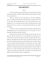
SOURCES OF AIR
Air in a pressurized, operating pipeline comes from three
primary sources. First, prior to start-up, the line is not
empty - it is full of air. To entirely fill a pipeline with fluid,
it is necessary to eliminate this air. As the line fills, much
of this air will be pushed downstream to be released
through hydrants, faucets, etc. but a large amount will
become trapped at system high points (Figure 1). This
phenomenon will occur because air is lighter than water
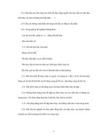
Figure 2
Air entering through mechanical equipment
AIR BUBBLES RISE
TO HIGHT POINT
INCREASING IN SIZE
FL
AIR COLLECTS AT HIGH POINT
OW
Figure 1
Air in pipeline collects at high points
and therefore, will collect at the high points. This air will
continuously be added to by the second and third sources
as the system continues operation.
Source number two is the water itself. Water contains
approximately 2% air by volume. During system operation, the entrained air will continuously separate out of the
water and once again accumulate at system high points.
To illustrate the potential massive amount of air this 2%
represents, consider the following: A 1000 ft. length of
pipe could contain a pocket of air 20 ft. long if all the air
accumulated in one location. Or a one mile length of pipe
could contain a 100 ft. pocket of air. This would be true
regardless of the diameter of the pipe.
The third source of air is that which enters through
mechanical equipment (Figure 2). This includes air being
forced into the system by pumps as well as air being
drawn in through packing, valves, etc. under vacuum conditions. As one can see, a pressurized pipeline is never
without air and typically the volume is substantial.
IMPACT OF AIR ON SYSTEM
Now that we have identified the air sources, let us consider
their impact on the system. Two problems are apparent.
The pocket(s) of air accumulating at a high point(s) can
result in a line restriction (Figure 3). Like any restriction, the
AIR BUBBLES
RISE TO HIGH POINT
INCREASING IN SIZE
FL
AIR COLLECTS AT HIGH POINT
OW
RESTRICTED FLOW
INCREASED VELOCITY
INCREASED HEAD LOSS
Figure 3
Air pockets can lead to line restriction
3
“Air in a pressurized pipeline is a serious concern. Obviously, its removal will result in a more
efficient, cost effective operation and potentially avoid more serious problems.”
pocket(s) of air increases headloss, extends pumping
cycles and increases energy consumption. The presence of
air can also promote corrosion of pipe and fittings. As air
continues to accumulate at system high points, the fluid
velocity increases as the fluid is forced through a smaller
and smaller opening.
can and often will, lead to a high pressure surge (water
hammer). Serious damage to valves, fittings, gaskets, or
even breakage of the line can occur. This is the most
serious of the possible consequences of air being allowed
to accumulate in system high points.
HISTORICAL SOLUTIONS
F
W
LO
Figure 4
Air pockets can lead to total flow stoppage
As the pocket(s) grows, one of two phenomena will occur.
The first possibility is a total flow stoppage (Figure 4). If system dynamics are such that the air cannot be continuously
removed by the increased fluid velocity and pushed downstream, then this could happen. As the pocket(s) continues to accumulate air, a pressure drop higher than pump
capacity can develop and stop all flow.
As we can see, air in a pressurized pipeline is a serious
concern. Obviously, its removal will result in a more efficient, cost effective operation and potentially avoid more
serious problems. In the early 1900's, engineers and water
works personnel started developing an understanding of
the problems associated with air and the search for a solution began. Some depended on standpipes, believing that a
large portion of the air would be expelled through them.
Hydrant
The second, and more likely occurrence, is that the
increased velocity will cause all, or part of, the pocket to
suddenly dislodge and be pushed downstream (Figure 5).
The sudden and rapid change in fluid velocity when the
pocket dislodges and is then stopped by another high point,
Air Pocket
FL
OW
Butterfly Valve
Distribution Line
Figure 6
Opening a hydrant may not eliminate air pockets
FL
OW
Part of air pocket breaks
away, creating surge
Figure 5
Air pockets can lead to surges in the line
4
Many began placing gate or ball valves at system high points
to manually bleed off accumulated air. Unfortunately, it has
proved impossible to predict when it is time to bleed the air.
This proved impractical, especially on larger systems. Open
fire hydrants (Figure 6) are frequently used under the
assumption that all air in the pipeline will be released.
Unfortunately, hydrants are generally connected to the side
of the pipe, leaving air trapped at the top and at system
high points. It should be noted that there are still municipalities using these methods.
“An added benefit of an Air/Vacuum Valve is its ability to provide pipeline vacuum protection. If a
negative pressure develops, the valve will open, admitting air into the line, reducing the potential for
surges related to column separation and possible pipeline collapse.”
AIR EXHAUST
THE AIR VALVE SOLUTION
Today, most municipalities utilize Automatic Air Valves.
They are available in many different designs and
configurations for a wide range of applications. Their
function is to automatically release and admit air without
operator assistance. Today, countless Air Valves are
performing this task around the globe on a daily basis.
Air Valves are available in three basic configurations
(Figure 7): Air Release Valves, Air/Vacuum Valves and
Combination Air Valves. Correct sizing and location of all
three types are critical. Every high point greater than one
pipe diameter where the pipeline converts from a positive
grade to a negative grade requires an air valve. Even minimal high points with small air pockets can cause serious
surge problems and reduce line efficiency. In addition, it
is recommended that air valves be installed every half
mile or 2500 feet on straight horizontal runs (AWWA
M51). Air Valve Sizing Software is available, see page 27.
WATER LEVEL
WATER LEVEL
AIR ENTERING
VALVE
CLOSED
POSITION
OPEN
POSITION
Figure 8
Air Release Valve in Operation
by water, raising the float and closing the valve orifice. As
air accumulates, the valve will continue to cycle in this
manner to remove collected air.
AIR/VACUUM VALVES
Air/Vacuum Valves (Figure 9), sometimes referred to as
"large orifice" valves, are used to exhaust large quantities
of air upon system start-up, as well as allowing air to reenter the line upon system shut down or system failure.
As water enters the valve, the float will rise, closing the discharge port. The valve will remain closed until system
pressure drops to near zero psi. It will not open to release
any accumulation of air while the system is under pressure.
Air Release Valve
AIR EXHAUSTING
Combination
Air Valve
OPEN
Air exhausted during
pipeline fill
Air/Vacuum Valve
Figure 7
WATER LEVEL
Basic Air Valve configurations
AIR RELEASE VALVES
An Air Release Valve (Figure 8), sometimes referred to as
a "small orifice" valve, will continuously release accumulated air during system operation. As air from the pipeline
enters the valve, it displaces the water, allowing the float
to drop. The air is then released into the atmosphere
through a small orifice. As the air is vented it is replaced
CLOSED
Pipeline under
pressure
AIR INTAKE
OPEN
Air enters during
pipeline draining
Figure 9
Air/Vacuum Valve Operation
5
An added benefit of an Air/Vacuum Valve is its ability to
provide pipeline vacuum protection. If a negative pressure
develops, the valve will open, admitting air into the line,
reducing the potential for surges related to column separation and possible pipeline collapse. While Air/Vacuum
Valves will exhaust large quantities of air upon start-up, it
should be remembered that they will not continuously
release air during system operation. For this function, an
Air Release Valve is also required.
COMBINATION AIR VALVES
Combination Air Valves (Figure 10) are the most commonly
used valves. They perform the functions of an Air/Vacuum
Valve (exhaust large quantities of air on start-up, admit air on
shut-down) and Air Release Valves (release air continuously
during operation). Combination Air Valves are available in
single body and dual body (an Air/Vacuum Valve and Air
Release Valve piped together) configurations. The single
body configuration is more compact and economical. The
severe vacuum pocket and the damaging pressures that
can occur when these pockets collapse. When the water
columns rejoin and the pressure recovers, the air valve
should exhaust the air in a regulated manner to suppress
surges. While the pipeline is pressurized and in operation,
the Air Valve must continue to automatically release
entrained air to maintain the pipeline flow efficiency.
Surge-Suppression Air Valves are Combination Air Valves
equipped with Regulated-Exhaust Devices (slow closing
devices) as shown in Figure 11. The Regulated-Exhaust
Air
Release
Valve
Air/Vacuum
Valve
AIR EXHAUST
Regulated-Exhaust
Device
Restrictor Disc
Ports
Figure 11
Surge-Suppression Air Valve
Figure 10
Single Body Combination Air Valve
dual body configuration provides two independent valves
so that if maintenance is being performed on the Air
Release Valve, the Air/Vacuum Valve is still protecting
the pipeline. The dual body valve also provides a much
wider range of sizing options.
SURGE-SUPPRESSION AIR VALVES
Pipelines with high points, where pressure transients or column separation can occur should have air valves equipped
with slow closing devices (regulated-exhaust device) to
restrict the outflow of air (AWWA C512-07). During these
conditions, typically caused by unexpected pump shut
down, line break, power outage etc., the air valve must
allow air to flow rapidly into the pipeline. The large volume
of air entering the pipeline will prevent the formation of a
6
Device consists of a flanged or threaded body with a normally-open restrictor disc. The Surge-Suppression Air Valve
provides full airflow into the pipeline during vacuum conditions to prevent a vapor pocket (vacuum) from forming.
When the pressure recovers and the water column rejoins,
air is expelled through the valve, which lifts the restrictor
disc. This action regulates the discharge airflow creating an
air pocket that cushions the surge effect of the returning
water column. When the column reaches the restrictor
disc, the water flows through the reduced ports and gently
closes the air valve. Transient studies (Kroon 1984,
Lingireddy 2004) have shown a dramatic reduction in pressure surges when the exhausting air is controlled under
these conditions.
WELL SERVICE AIR VALVES
Well Service Air Valves (Figure 12) are a member of the
Air/Vacuum Valve family and are used with vertical pumps.
Vertical pumps (Figure 2) lift water from a reservoir or deep
well at high velocities because they start against little head
and a pump column filled with air. Well Service Air Valves
are specifically designed to vent the air from the pump column during pump start-up in a controlled manner before
the check valve opens to reduce pressure surges that result
from the accelerating water column.
Val-Matic provides Dual Port Throttling Devices (Figure 12)
on the outlet of ½ to 3 in. Well Service Air Valves. The Dual
Port Throttling Device regulates the exhaust rate through
an adjustable exhaust port and provides full vacuum flow
through a separate vacuum port during pump shutdown.
This exclusive feature of the Dual Port reduces any potential for contaminated water being drawn into the system by
vacuum during the pump shut down.
Vacuum Port (Full Flow)
Figure 13
Adjustable
Exhaust Discharge
Port
Pipe
Dual Port
Throttling
Device
Vacuum Breaker with Air Release Valve
(Open Position)
When positive pressure in the system is restored, the
Vacuum Breaker provides a positive resilient seal to maintain system pressure. When equipped with an Air Release
Valve, the Air Release Valve is used to slowly exhaust the air
that was admitted to the pipeline. The slow release of air
prevents the sudden rejoining of separated columns in a
pipeline and the associated pressure surges or water hammer.
Well Service
Air Valve
SUMMARY
Air Exhaust
Figure 12
Well Service Air Valve with Dual Port Throttling Device
Val-Matic provides Regulated-Exhaust Devices on the inlet
of 4 in. and larger (see Figure 11) Well Service Air Valves.
The Regulated-Exhaust Device provides controlled air
exhaust during start-up and full vacuum flow during shut
down. The device controls the flow of air and water into the
air valve and is effective in suppressing water hammer in
the pump column and air valve during pump start-up.
When air is allowed to accumulate in pressurized
pipelines, efficiency is sacrificed and serious damage
can occur. A properly de-aerated pipeline will not solve
all surge problems; however, the elimination of air can
solve one of the most common causes. Air Valves are a
cost effective, reliable method of improving efficiency and
solving air related surge problems.
REFERENCES
Kroon, R. "Water Hammer: Causes and Effects," AWWA
Journal. Nov., 1984. pp. 39-45.
Lingireddy, "Pressure Surges in Pipeline Systems Resulting
From Air Releases," AWWA Journal. July, 2004. pp. 88-94.
VACUUM BREAKER VALVES
For critical applications where vacuum protection is a must
or where column separation is predicted, a vacuum breaker (Figure 13) is used. The Vacuum Breaker is mounted at
critical pipeline high points, penstocks, or tanks and allows
for rapid inflow of atmospheric air to reduce vacuum conditions in piping systems.
7
Features & Benefits
rom the float material to the shape of the
body, Val-Matic Air Valves are designed for
optimum performance. All valves meet AWWA
C512 requirements.
F
EXPERIENCE
Val-Matic offers over 40 years of experience in providing
a full line of air valves up to 20 inch and vacuum breakers up to 42 inch in size. The Val-Matic Air Release,
Air/Vacuum and Combination Air Valves are manufactured in accordance to the rigorous industry requirements given in American Waterworks Association
(AWWA) Standard C512. The standard was developed
and based on decades of successful application of air
valves in our industry. Val-Matic’s AWWA Air Valves feature 316 stainless steel trim, full size ports, ANSI threaded or flanged connections and stringent testing. ValMatic manufactures air valves in a wide range of materials and pressure ratings with many accessories including Regulated-Exhaust Devices, Dual Port Throttling
Devices, Isolation Valves, Screened Hoods and
Backwash Accessories. Val-Matic also provides
Windows-Based software to locate, select and size air
valves for pipelines and force mains.
NSF/ANSI 61 CERTIFICATION
Val-Matic Air Valves for water service are independently
NSF/ANSI 61 certified and marked for use in drinking
water applications.
TYPE 316 STAINLESS STEEL TRIM
Type 316 stainless steel is the standard for all internal
components in Val-Matic Air Valves. Type 316 stainless
steel provides the greatest protection from aggressive
waters and hydrogen sulfide exposure in wastewater
application.
UNCONDITIONALLY GUARANTEED
FLOATS
Floats are unconditionally guaranteed for the life of
the valve from corrosion, collapse or leakage. No other
valve manufacturer has the confidence in their float
construction to provide this guarantee.
GUIDED FLOATS
Providing a quality float is not enough to assure a
good seal every time. When entering the seat, a
damaged or off-center float will prevent a valve
8
from sealing tight. The high air and water velocities in
air valves can cause unguided floats to
violently strike the sides of the valve
body. Val-Matic floats are guided; four
inch and larger valves feature double
guides (top and bottom). Guiding
assures that the float approaches the
center of the seat every time to provide a
positive drop tight seal.
SELF CLEANING FLOAT GUIDES
The Val-Matic floats are guided by hexagonal float
stems. The float stems pass through round stainless
steel bushings preventing the build up of debris or scale
and provide self cleaning of the bushings.
RESILIENT SEATS
All Val-Matic valves incorporate a resilient seat or orifice
button which mates with a 316 stainless steel float or
seat for positive drip tight seating. Val-Matic elastomers
are specially formulated for water and wastewater service and have been NSF/ANSI 61 certified. Air Release
Valves have a synthetic sealing button mounted to the
float linkage mechanism. On Air/Vacuum and
Combination Air Valves, the stainless steel float closes
against the resilient seat mechanically retained in a
body register. The seats contain raised sealing beads
and/or a unique flex edge that provide positive shutoff
from the lowest system pressure to the valve’s rated
working pressure.
FULL SIZE FLOW AREA
Val-Matic Air/Vacuum and Combination Air Valves are
equipped with full and equal size inlets and outlets in
accordance with AWWA C512. Some air valve manufacturers use common covers for different size air valves
resulting in undersized outlets and reduced flow.
Standard industry calculations assume a full port
size so the air valve should provide the same.
You can be assured that the inlets and outlets
of Val-Matic’s Air Valves are equal to or larger
than the area of the nominal valve size. Finally,
all Combination Air Valves with float guides in
the outlet have expanded flow areas around
the guide spokes to provide full flow area
through the valve.
Additional Features & Benefits for
Wastewater Valves
STAINLESS STEEL BODY
Cast stainless steel bodies are available for extreme service where hydrogen sulfide or industrial chemicals produce
accelerated corrosion in iron. There are no weld-seams to
worry about with the cast stainless body and it is in full
compliance with AWWA C512.
QUICK DISCONNECT COUPLINGS
1/2” BRONZE FULL FLOW
BALL VALVE WITH QUICK
DISCONNECT COUPLING
NON-STICK COATINGS
Special interior coatings are available to minimize the
buildup of sewage on the inside of the valve. Val-Matic’s
Fusion Bonded Epoxy is a baked-on, glass-like coating that
reduces maintenance and prevents corrosion of the valve.
Non-stick coatings are important when force mains contain grease that tends to collect in valves and pipes.
NON-CLOG DESIGN FOR REDUCED
MAINTENANCE
Val-Matic Wastewater Air Valves are specially designed for
grit and sewage service without the need for backwashing
when combined with non-stick coatings. The bodies are
extended in length to prevent solid material from reaching
the operating mechanism. The bottom of the body is
sloped toward the outlet to prevent clogging (See Figure
14). Val-Matic provides a minimum 2” inlet size and a 2”
cleanout connection on all wastewater valves to facilitate
the passage of solids.
WASTEWATER FLOATS
As with all Val-Matic Air Valves, the float and operating
mechanism are 316 stainless steel for long life in the
harshest wastewater applications. Additionally, the floats
are equipped with a specially shaped bottom to accelerate
the closure of the float to reduce leakage and clogging of
the valve.
SEVERE SERVICE BACKWASHING
When systems are heavy in grease and solids, backwashing of Wastewater Air Valves may become a necessary
maintenance process. The key is to reduce the frequency
of backwashing by designing the valve to handle conditions such as wastewater containing solids and grease. As
indicated in the above features, Val-Matic has done that
with the extended body, the Bell Bottom, the sensitivity
float and the availability of non-stick Fusion Bonded Epoxy.
However, periodic maintenance may still be required on
severe applications. Therefore, all Wastewater Air Valves
SENSATIVITY
FLOAT
1/2” RUBBER HOSE WITH
QUICK DISCONNECT
COUPLING ON EACH END
1” BRONZE
FULL FLOW
BALL VALVE
2“ CLEANOUT
BRONZE
FULL FLOW
ISOLATION
BALL VALVE
Figure 14
Air Valve with Severe Service Backwash Accessories
can be furnished with an accessory kit which includes a
shutoff valve to isolate the air valves from the line, flush
and drain valves, and a hose for connecting to a clean
water supply.
Backwashing is as simple as: 1) isolating the air valve, 2)
opening the drain valve, and 3) opening the flush valves to
send clean water through the valve body for 5 minutes.
For those installations where backwashing on site is not
practical or desirable, a valve rotation program can be
established. The valve to be serviced is exchanged with a
spare valve and taken back to the shop for cleaning. It is
then ready to replace the next valve scheduled for maintenance. The valve rotation program also provides the benefit of a back up valve in the unlikely event one should ever
fail.
9
Look to Val-Matic for Solutions
he wide range of air related concerns in pipeline
and treatment plant design require a multitude of
solutions. With the broadest line of air valves
available coupled with Engineering expertise and
Manufacturing experience, Val-Matic is the number one
source for solutions to air related issues. The following
are a few of the basic valve applications and the solutions Val-Matic can provide.
T
EFFICIENCY AND VACUUM
PROTECTION
The primary purpose of air valves is to provide pipeline efficiency by continuous removal of air at pipeline highpoints
and vacuum protection by admitting large quantities of air
upon pump shut down or system failure.
rejoin. To prevent a vacuum from forming, a SurgeSuppression Air Valve or Vacuum Breaker is used to
admit large quantities of air into the pipeline.
A Surge-Suppression Air Valve consists of a Combination
Air Valve equipped with a Regulated-Exhaust Device that
allows full airflow into the pipeline, but restricts the airflow out of the pipeline. Similarly, a Vacuum Breaker
allows rapid entry of air into the pipeline, but prevents
flow out of the pipeline. When equipped with an Air
Release Valve, the Vacuum Breaker will provide controlled release of air through the small Air Release Valve
orifice. Both methods dampen or suppress surges in the
pipeline by temporarily trapping a pocket of air and cushioning the impact of the returning columns of water by
regulating the exhaust of the air pocket.
SURGE CONTROL
VERTICAL PUMP COLUMN SURGES
Air valves play an important role in pipelines to control
or reduce surges. Surges result from sudden changes in
velocity of the pipeline fluid. These velocity changes
occur regularly due to pipeline filling, pump operation,
line breaks and power failure. The effects of surges can
be devastating. Surges are typically 50 psi for every 1
ft/sec of rapid change in flow velocity. This is added to
the pipeline static pressure. Through computer modeling and transient analysis, it has been shown that air
valves can play a critical role in suppressing pipeline
surges during column separation conditions.
PIPELINE SURGES
Power or system failures can often result in water column
separation at high points in the line. If the water column
is allowed to separate and form a vacuum pocket, a devastating surge can occur when the columns
10
High velocity rapidly develops in a pump column when a vertical turbine or deep well pump starts against an air-filled column and closed check valve. A power-actuated check valve
must absorb the full force of the impending impact. A
mechanical check valve will open, relieving a portion of the
force but still sees extreme surges. The best way to prevent
surges in the pump column and connecting piping is to regulate the exhaust of the air in the pump column during pump
start-up (AWWA M-51, p. 24). A Well Service Air Valve
equipped with either a Dual Port Throttling Device or a
Regulated-Exhaust Device vent air from the pump column at
a controlled rate so that all or most of the air escapes just
before the check valve opens. (See Val-Matic technical
paper AEG-302.)
/V
ac
u
Air
Air
Re
le
as
eV
alv
e
Val-Matic Air Valves fully
comply with ANSI/AWWA
C512 and are NSF/ANSI 61
Certified for Water Quality.
um
Va
Co
lve
mb
ina
tio
nA
Su
ir V
rge
alv
-Su
e
pp
r
e
Va
s
sio
cu
nA
um
ir V
Br
e
alv
ak
We
e
e
ll S
rV
alv
er
vic
e
eA
Wa
ir V
ste
alv
wa
e
ter
Air
Wa
Re
ste
lea
wa
se
ter
Va
Air
Wa
lve
/
ste
Va
cu
wa
um
ter
Va
Va
Co
lve
cu
mb
um
ina
Pr
tio
im
nV
ing
alv
Va
e
lve
Applications, Functions, Purpose & Features
PIPELINE APPLICATIONS
Water distribution and transmission
x
x
x
Municipal wastewater collection
Force Main
x
x
x
x
x
x
x
x
x
x
x
x
x
x
x
PUMP APPLICATIONS
Centrifugal pump volute
Lift station
x
Pump station high points
x
x
x
Turbine well pump discharge
Booster pump station
Fire pumps (FM Approved, UL Listed)
x
x
x
x
x
x
x
x
WATER/WASTEWATER TREATMENT PLANT APPLICATIONS
High Points
Filter backwash piping
Pressure filters
Venturi meters
x
x
x
x
x
x
x
x
x
x
TANK APPLICATIONS
Storage tank valves
Hydropneumatic tanks
x
x
x
x
x
x
x
x
x
x
x
x
x
x
x
x
x
x
x
x
x
x
x
x
x
x
x
FUNCTION
Venting of accumulated air during system operation
Admitting large volumes of air during shut down and
draining operations (Power failure)
x
Vacuum protection (pipe joints, gaskets, packing, etc.)
Regulated-Exhaust of large volumes of air during start-up
and filling operations
PURPOSE
Maintain pipeline efficiency
Provide protection from pipeline collapse due to vacuum
Air related surge protection
Air related head loss protection (efficiency)
Column separation vacuum protection
Air bound pump protection
Extend air valve life
Maintain pump prime
Reduce Air/Vacuum valve size requirement
FEATURES
Conforms to AWWA standard
Certified to NSF/ANSI 61
Adjustable seating
Full flow area equal to nominal valve size
Inlets and Outlets equal to or greater
than the nominal valve size
Single and dual body designs
Bell bottom body (anti-clog)
Regulated-Exhaust Device (Slow-Closing Device)
x
x
x
x
x
x
x
x
x
x
x
x
x
x
x
x
x
x
x
x
x
x
x
x
x
x
x
x
x
x
x
x
x
x
x
x
x
x
x
x
x
x
x
x
x
x
x
x
x
x
x
x
x
x
x
x
x
x
x
x
x
x
x
x
x
x
x
x
x
x
x
x
x
x
11
Air Release Valves
Operational Highlights:
• Maintains system flow efficiency
• Releases unwanted air pockets during system operation
• Protects system against air related surges
Product Features:
• Unconditionally guaranteed stainless steel floats
• Stainless steel 316 internal trim
• Resilient seating for positive shutoff
• Performance proven for over 40 years
• Non-clog design eliminates backwashing
Optional Accessories:
• Vacuum check (prevents inflow of air)
• Outlet hood with screen (prevents debris from entering valves)
• Ball and plug isolation valves (allows valve maintenance)
• Inflow Preventer on outlet (stops flood water and resulting
contamination from entering pipeline)
• Backwash kit (for severe wastewater applications)
Wastewater
Clean Water*
*
MATERIALS OF CONSTRUCTION
COMPONENT
STANDARD
OPTIONAL
Body and Cover
Cast Iron ASTM A126 Class B
< 300 psig
Ductile Iron ASTM A536 Grade 65-45-12
Stainless Steel ASTM A351 Grade CF8M
Trim
Type 316 Stainless Steel
--
Coating
Universal Alkyd Primer (external)
Non-Stick Fusion Bonded Epoxy (internal & external)
Venting Capacity for Air Release Valve Orifice Sizes
12
Air Release Valves
Installation Dimensions
WATER AIR RELEASE VALVES
Inlet
Size
Outlet
Size
Model
Number
CWP
PSI
Orifice Size
1/2” NPT
3/4” NPT
1” NPT
1” NPT
1/2” - 3/4” NPT
1/2” NPT
1/2” - 1” NPT
3/4” - 1” NPT
3/4” - 1” NPT
1” NPT
1” NPT
2” NPT
1” NPT
2” NPT
2” NPT
2” NPT
3” NPT
2” NPT
3” NPT
2” NPT
2” NPT
6” 125lb Flg
1/2” NPT
1/2” NPT
1/2” NPT
1/2” NPT
1/2” NPT
1/2” NPT
1/2” NPT
1/2” NPT
1/2” NPT
1/2” NPT
1/2” NPT
1/2” NPT
1/2” NPT
1/2” NPT
1” NPT
1” NPT
1” NPT
1” NPT
1” NPT
1” NPT
1” NPT
1” NPT
15A*•
15A.2*•
15A.3*•
22.3*•
22.4*•
22.7*•
22.9*
25.5*
25.6*
38*
38HP*
38.2*
38.5*
38.6*
45*
45HP*
45.2*
45.5*
45.6*
50*
50HP*
61*
175
175
175
175
175
300
300
150
300
150
500
150
300
300
150
400
150
300
300
500
1000
150
1/16”
1/16”
1/16”
3/32”
3/32”
1/16”
1/16”
1/8”
3/32”
3/16”
1/8”
3/16”
5/32”
5/32”
23/64”
3/16”
23/64”
7/32”
7/32”
7/32”
1/8”
1”
*NSF/ANSI 61 Certified
Dimensions
A
4 3/4”
4 3/4”
4 3/4”
5 1/8”
5 1/8”
5 1/8”
5 1/8”
6 1/8”
6 1/8”
7”
7”
7”
7”
7”
9 1/2”
9 1/2”
9 1/2”
9 1/2”
9 1/2”
10 7/8”
10 7/8”
18 3/4”
B
5 1/4”
5 1/4”
5 1/4”
6”
6”
6”
6”
7”
7”
10”
10”
10”
10”
10”
12 1/4”
12 1/4”
12 1/4”
12 1/4”
12 1/4”
13”
13”
22”
A
B
15A - 50HP
Air Release Valve
A
B
61
Air Release Valve
•UL Listed/FM Approved
A
WASTEWATER AIR RELEASE VALVES
Inlet
Size
Outlet
Size
Model
Number
CWP
PSI
Orifice Size
2” NPT
3” NPT
2” NPT
3” NPT
2” NPT
3” NPT
2” NPT
3” NPT
4” NPT
1/2” NPT
1/2” NPT
1/2” NPT
1/2” NPT
1” NPT
1” NPT
1” NPT
1” NPT
1” NPT
48A
48A.2
48A.4
48A.5
49A
49A.2
49A.4
49A.5
49A.6
150
150
75
75
150
150
75
75
75
3/16”
3/16”
5/16”
5/16”
7/16”
7/16”
1/2”
1/2”
1/2”
Dimensions
A
7”
7”
7”
7”
9 1/2”
9 1/2”
9 1/2”
9 1/2”
9 1/2”
B
15 5/16”
15 5/16”
15 5/16”
15 5/16”
17 9/16”
17 9/16”
17 9/16”
17 9/16”
17 9/16”
B
48A - 49A.6
Wastewater Air
Release Valves
13
Air/Vacuum Valves
Operational Highlights:
• Exhausts large quantities of air at system start-up
• Provides pipeline vacuum protection
• Responds to loss of pressure during power failures, line breaks
and intentional drainage
Product Features:
• Unconditionally guaranteed stainless steel floats
• Stainless steel 316 internal trim
• Exclusive high/low pressure resilient seating
• Full pipe size inlets and outlets provide maximum protection
• Non-clog design eliminates backwashing
Optional Accessories:
• Outlet hood with screen (prevents debris from entering valves)
• Flanged outlets on sizes 8 inch & smaller
• Ball, plug, and butterfly isolation valves (allows valve maintenance)
• Inflow Preventer on outlet (stops flood water and resulting
contamination from entering pipeline)
• Backwash kit (for severe wastewater applications)
Clean Water*
Wastewater
*
MATERIALS OF CONSTRUCTION
COMPONENT
STANDARD
OPTIONAL
Body and Cover
Cast Iron ASTM A126 Class B
Class 125 and 250
Ductile Iron ASTM A536 Grade 65-45-12
Stainless Steel ASTM A351 Grade CF8M
Trim
Type 316 Stainless Steel
-
Coating
Universal Alkyd Primer (external)
Non-Stick Fusion Bonded Epoxy (internal & external)
FLOW CAPACITY OF AIR/VACUUM VALVES
14
Air/Vacuum Valves
Installation Dimensions
A
WATER AIR/VACUUM VALVES
Dimensions
Inlet
Size
Outlet
Size
Model
Number
CWP
PSI
A
B
1/2” NPT
1/2” NPT
100S
300
6 1/8”
7”
1” NPT
1” NPT
101S
300
7”
9 1/2”
2” NPT
2” NPT
102S
300
9 1/2”
12”
3” NPT
3” NPT
103S
300
9 1/2”
12”
4” Flg
4” NPT
20 3/4”
6” NPT
14”
18 5/8”
8” Flg
8” NPT
17 1/4”
21 5/8”
10” Flg
10” Flg
20”
26”
12” Flg
12” Flg
24”
31”
14” Flg
14” Flg
27”
34”
16” Flg
16” Flg
30 1/2”
34”
20” Flg
20” Flg
125lb - 150
250lb - 300
125lb - 150
250lb - 300
125lb - 150
250lb - 300
125lb - 150
250lb - 300
125lb - 150
250lb - 300
125lb - 150
250lb - 300
125lb - 150
250lb - 300
125lb - 150
250lb - 300
12”
6” Flg
104S
154S
106S
156S
108S
158S
110F
160F
112F
162F
114F
164F
116F
166F
120F
170F
38 1/4”
36 1/4”
B
100S - 103S
Air/Vacuum Valves
A
B
104S - 170F
Air/Vacuum Valves
A
WASTEWATER AIR/VACUUM VALVES
Dimensions
Inlet
Size
Outlet
Size
Model
Number
CWP
PSI
A
B
2” NPT
1” NPT
301A
150
7”
15 1/16”
2” NPT
2” NPT
302A
150
9 1/2”
17 7/16”
3” NPT
3” NPT
303A
150
9 1/2”
17 7/16”
4” Flg
4” NPT
304
150
11 1/2”
36 1/2”
6” Flg
6” NPT
306
150
14”
36 1/2”
8” Flg
8” NPT
308
150
17 1/4”
40 1/8”
B
301A - 308
Wastewater Air/Vacuum Valves
15
Combination Air Valves
Operational Highlights:
• Provides the functions of both Air Release and Air/Vacuum Valves
• Exhausts large quantities of air at system start-up
• Releases air pockets during system operation
• Provides pipeline vacuum protection
Product Features:
• Single body incorporates both features within one valve
– More compact and economical
• Dual body consists of two independent valves
– Allows individual maintenance while still
protecting the pipeline
–Wider range of sizing options
• Inlets and outlets are equal to full nominal size
• Unconditionally guaranteed stainless steel floats
• Stainless steel 316 internal trim
• Non-clog design eliminates backwashing
• Exclusive high/low pressure resilient seating
Clean Water*
Wastewater
Optional Accessories:
• Outlet hood with screen (prevents debris from entering valves)
• Ball, plug and butterfly isolation valves (allows valve maintenance)
• Inflow Preventer on outlet (stops flood water and resulting
contamination from entering pipeline)
• Backwash kit (for severe wastewater applications)
*
MATERIALS OF CONSTRUCTION
COMPONENT
STANDARD
OPTIONAL
Body and Cover
Cast Iron ASTM A126 Class B
Class 125 and 250
Ductile Iron ASTM A536 Grade 65-45-12
Stainless Steel ASTM A351 Grade CF8M
Trim
Type 316 Stainless Steel
-
Coating
Universal Alkyd Primer (external)
Non-Stick Fusion Bonded Epoxy (internal & external)
FLOW CAPACITY OF COMBINATION AIR VALVES
16
Combination Air Valves
Installation Dimensions
A
WATER COMBINATION AIR VALVES (SINGLE BODY)
Dimensions
Inlet
Size
Outlet
Size
Model
Number
CWP
PSI
Orifice Size
1” NPT
1” NPT
201C.2
300
2” NPT
2” NPT
202C.2
3” NPT
3” NPT
3” 125lb Flg
A
B
5/64”
11 3/8”
10 1/2”
300
3/32”
14”
13”
203C.2
300
3/32”
16”
15”
3” NPT
203C.14
150
3/32”
16”
16 3/4”
3” 250lb Flg
3” NPT
203C.15
300
3/32”
16”
17 1/4”
4” NPT
4” NPT
204C.2
300
3/32”
18 1/2”
17”
4” 125lb Flg
4” NPT
204C.14
150
3/32”
18 1/2”
19 3/4”
4” 250lb Flg
4” NPT
204C.15
300
3/32”
18 1/2”
20 1/4”
6” 125lb Flg
6” NPT
206C
150
3/8”
21”
20 1/4”
6” 250lb Flg
6” NPT
256C
300
7/32”
21”
20 1/4”
8” 125lb Flg
8” NPT
208C
150
3/8”
25”
23 1/2”
8” 250lb Flg
8” NPT
258C
300
7/32”
25”
23 1/2”
B
201C.2 - 204C.15
Single Body Combination
Air Valves
A
B
206C - 258C
Single Body
Combination Air Valves
A
WASTEWATER COMBINATION AIR VALVES (SINGLE BODY)
Dimensions
Inlet
Size
Outlet
Size
Model
Number
CWP
PSI
Orifice Size
2” NPT
1” NPT
801A
150
2” NPT
2” NPT
802A
3” NPT
3” NPT
4” NPT
4” NPT
A
B
1/8”
7”
14 15/16”
150
9/64”
9 1/2”
18 1/16”
803A
150
11/64”
11”
23 1/2”
804
150
11/64”
11”
23 1/2”
B
801A - 804
Wastewater
Single Body Combination
Air Valves
Surge-Suppression Air Valves and Isolation Valves in a pump discharge application.
17
Combination Air Valves
Installation Dimensions
A
WATER COMBINATION AIR VALVES (DUAL BODY)
B
Dimensions
A
B
Inlet
Size
Outlet
Size
Model
Number
CWP
PSI
Orifice Size
1” NPT
1” NPT
101S/22.9
300
1/16”
7 7/8”
15 5/8”
2” NPT
2” NPT
102S/22.9
300
1/16”
10 1/4”
17 7/8”
3” NPT
3” NPT
103S/22.9
300
1/16”
10 1/4”
18 1/4”
101S/22.9 - 103S/22.9
Dual Body Combination
Air Valves
WATER COMBINATION AIR VALVES (DUAL BODY)
A
B
104S/38 - 166F/45.5
Dual Body Combination
Air Valves
18
Inlet
Size
Outlet
Size
Air/Vacuum
Model
Number
CWP
PSI
Orifice Size
Air Release
4” Flg
4” NPT
104S/38
154S/38.5
125lb - 150
250lb - 300
6” Flg
6” NPT
106S/38
156S/38.5
8” Flg
8” NPT
8” Flg
Dimensions
A
B
3/16”
5/32”
21”
22”
125lb - 150
250lb - 300
3/16”
5/32”
24”
23”
108S/38
158S/38.5
125lb - 150
250lb - 300
3/16”
5/32”
27”
26”
8” NPT
108S/45
158S/45.5
125lb - 150
250lb - 300
23/64”
7/32”
30”
29”
10” Flg
10” Flg
110F/38
160F/38.5
125lb - 150
250lb - 300
3/16”
5/32”
30”
28”
10” Flg
10” Flg
110F/45
160F/45.5
125lb - 150
250lb - 300
23/64”
7/32”
33”
31”
12” Flg
12” Flg
112F/38
162F/38.5
125lb - 150
250lb - 300
3/16”
5/32”
33”
32”
12” Flg
12” Flg
112F/45
162F/45.5
125lb - 150
250lb - 300
23/64”
7/32”
37”
34”
14” Flg
14” Flg
114F/38
164F/38.5
125lb - 150
250lb - 300
3/16”
5/32”
36”
34”
14” Flg
14” Flg
114F/45
164F/45.5
125lb - 150
250lb - 300
23/64”
7/32”
40”
36”
16” Flg
16” Flg
116F/38
166F/38.5
125lb - 150
250lb - 300
3/16”
5/32”
39”
34”
16” Flg
16” Flg
116F/45
166F/45.5
125lb - 150
250lb - 300
23/64”
7/32”
44”
37”
Combination Air Valves
Installation Dimensions
WASTEWATER COMBINATION AIR VALVES (DUAL BODY)
A
Dimensions
Inlet
Size
Outlet
Size
Model
Number
CWP
PSI
Orifice
Size
A
B
2” NPT
1” NPT
48A/301A
150
3/16”
20 5/16”
20 5/16”
2” NPT
1” NPT
49A/301A
150
7/16”
19 1/2”
22 3/4”
2” NPT
2” NPT
48A/302A
150
3/16”
20 3/4”
25 3/4”
2” NPT
2” NPT
49A/302A
150
7/16”
20 3/4”
22 3/4”
3” NPT
3” NPT
48A/303A
150
3/16”
21 1/2”
28 1/4”
3” NPT
3” NPT
49A/303A
150
7/16”
21 1/2”
24 3/4”
B
48A/301A - 49A/303A
Dual Body Wastewater
Combination Air Valves
WASTEWATER COMBINATION AIR VALVES (DUAL BODY)
Dimensions
Inlet
Size
Outlet
Size
Model
Number
CWP
PSI
Orifice
Size
A
B
4” Flg
4” NPT
48A/304
150
3/16”
20 3/4”
36 1/2”
4” Flg
4” NPT
49A/304
150
7/16”
20 3/4”
36 1/2”
6” Flg
6” NPT
48A/306
150
3/16”
23 1/4”
36 1/2”
6” Flg
6” NPT
49A/306
150
7/16”
23 1/4”
36 1/2”
8” Flg
8” NPT
48A/308
150
3/16”
25 3/4”
41 1/4”
8” Flg
8” NPT
49A/308
150
7/16”
27 1/2”
41 1/4”
A
B
48A/304 - 49A/308
Dual Body Wastewater
Combination Air Valves
Air Valves are commonly found in plant service as well as pipelines for efficiency and
protection. The model shown above is a 48A/308 with flanged outlet and optional
Cam-Centric® Plug Valve for isolation and maintenance.
19
Surge-Suppression Air Valves
Operational Highlights:
• Provides full vacuum protection for the pipeline
• Provides slow closure suppressing surge in the pipeline
• Minimizes water blow-by during Air Valve closure
• Allows the use of smaller valve size by utilizing a maximum
sizing differential pressure of 5 psig
• Releases entrained air while pipeline is operating to maintain
pumping efficiency
• Fully complies with AWWA C512 and NSF 61
Surge-Suppression Air Valve Features:
• Restrictor disc provides regulated exhaust to limit secondary
surges during column separation
• Ability to adjust air exhaust for greater surge suppression
• Provides full vacuum flow port
Optional Accessories:
Clean Water*
• Outlet hood with screen (prevents debris from entering valves)
• Ball and butterfly isolation valves (allows valve maintenance)
• Inflow Preventer on outlet (stops flood water and resulting
contamination from entering pipeline)
• Backwash kit (for severe wastewater applications)
Wastewater
*
MATERIALS OF CONSTRUCTION
COMPONENT
STANDARD
OPTIONAL
Body
Cast Iron ASTM A126 Class B
Ductile Iron ASTM A536 Grade 65-45-12
Trim
Type 316 Stainless Steel (Air Valve)
Bronze ASTM B584 C83600 (Reg. Exh. Dev.)*
Stainless Steel ASTM A351 Grade CF8M
(Reg. Exh. Dev.)*
Exterior Coating
Universal Primer (external)
Non-Stick Fusion Bonded Epoxy (internal & external)
*(Reg. Exh. Dev.) = Regulated-Exhaust Device
FLOW CAPACITY OF SURGE-SUPPRESSION AIR VALVES
20
Surge-Suppression Air Valves
Installation Dimensions
WATER SURGE-SUPPRESSION AIR VALVES (SINGLE BODY)
Inlet
Size
Outlet
Size
CWP Orifice
Size
PSI
Model Number
1” NPT
1” NPT
201CSS
250
2” NPT
2” NPT
202CSS
3” 125lb Flg
3” NPT
3” 250lb Flg
A
Dimensions
A
B
5/64”
11 3/8”
13 5/8”
250
3/32”
14”
17 1/4”
203CSS
300
3/32”
16”
22 3/4”
3” NPT
253CSS
300
3/32”
16”
22 3/4”
4” 125lb Flg
4” NPT
204CSS
300
3/32”
18 1/2”
27”
4” 250lb Flg
4” NPT
254CSS
300
3/32”
18 1/2”
27”
6” 125lb Flg
6” NPT
206CSS
150
3/8”
21”
30”
8” 250lb Flg
8” NPT
256CSS
300
7/32”
21”
30”
6” 125lb Flg
6” NPT
208CSS
150
3/8”
25”
36”
8” 250lb Flg
8” NPT
258CSS
300
7/32”
25”
36”
B
203CSS - 258CSS
Surge-Suppression Single Body
Air Valves
WATER SURGE-SUPPRESSION AIR VALVES (DUAL BODY)
Inlet*
Size
Outlet**
Size
CWP Orifice
PSI
Size
Model Number
4” 125lb Flg
4” NPT
104SS/38
150
4” 250lb Flg
4” NPT
154SS/38.5
6” 125lb Flg
6” NPT
6” 250lb Flg
A
Dimensions
A
B
3/16”
21”
29”
300
5/32”
21”
29”
106SS/38
150
3/16”
22 1/2”
33”
6” NPT
156SS/38.5
300
5/32”
22 1/2”
33”
8” 125lb Flg
8” NPT
108SS/38
150
3/16”
27”
38”
8” 250lb Flg
8” NPT
158SS/38.5
300
5/32”
27”
38”
10” 125lb Flg
10” Flg
110FSS/45
150
23/64”
33”
47”
10” 250lb Flg
10” Flg
160FSS/45.5
300
7/32”
33”
47”
12” 125lb Flg
12” Flg
112FSS/45
150
23/64”
37”
48 1/2”
12” 250lb Flg
12” Flg
162FSS/45.5
300
7/32”
37”
48 1/2”
* For sizes 14” - 20” Consult Factory
**All outlet flanges are class 125 lb.
B
104SS/38 - 162FSS/45.5
Surge-Suppression Dual Body
Air Valves
A
WASTEWATER SURGE-SUPPRESSION AIR VALVES (SINGLE BODY)
Inlet
Size
Outlet
Size
Model Number
2” NPT
1” NPT
2” NPT
Dimensions
CWP Orifice
Size
PSI
A
B
801SS
150
1/8”
7”
18”
2” NPT
802SS
150
9/64”
9 1/2”
23”
3” NPT
3” NPT
803SS
150
11/64”
11”
33”
4” NPT
4” NPT
804SS
150
11/64”
11”
34”
B
801SS - 804SS
Surge-Suppression Single Body
Air Valves
21
Well Service Air Valves
Operational Highlights:
• Regulates the exhaust of air on pump start-up
• Admits air to protect pump and mechanical seals
• Protects against air-related surges on pump start-up
• Fully complies with AWWA C512 and NSF 61
Product Features:
• Unconditionally guaranteed 316 stainless steel floats
• Inlets and outlets are equal to full nominal pipe area
• 1/2" - 3" equipped with Dual Port Throttling Device
• 4" and larger equipped with Regulated-Exhaust Device mounted on
the inlet
Dual Port Throttling Device:
• Adjustable discharge outlet provides regulated air exhaust
• Allows air to enter the system on pump shut down through an
unrestricted independent vacuum port
1 - 3 inch
4 inch & larger
Regulated-Exhaust Device:
• Retrictor disc provides regulated exhaust to limit pump column surges
• Ability to adjust air exhaust for greater surge suppression
• Provides full vacuum flow port
MATERIALS OF CONSTRUCTION
COMPONENT
STANDARD
OPTIONAL
Body and Cover
Cast Iron ASTM A126 Class B
Class 125 and 250
Ductile Iron ASTM A536 Grade 65-45-12
Stainless Steel ASTM A351 Grade CF8M
Trim
Type 316 Stainless Steel (Air Valve)
Bronze ASTM B584 C83600 (Reg. Exh. Dev.)*
-
Coating
Universal Alkyd Primer (external)
Non-Stick Fusion Bonded Epoxy (internal & external)
*(Reg. Exh. Dev.) = Regulated-Exhaust Device
WELL SERVICE AIR VALVE SIZING
VALVE
SIZE
22
MODEL NUMBER
NO HEAD PUMP
CAPACITY, GPM 150 PSI MODEL 300 PSI MODEL
1/2”
0 - 350
100ST
1”
351 - 1,350
101ST
2”
1,351 - 4,000
102ST
3”
4,001 - 7,000
103ST
4”
7,001 - 11,000
104SS
154SS
6”
11,001 - 24,000
106SS
156SS
8”
24,001 - 50,000
108SS
158SS
10”
50,001 - 70,000
110FSS
160FSS
12”
70,001 - 110,000
112FSS
162FSS
Well Service Air Valves
Installation Dimensions
A
Well Service Air Valve
with Dual Port Throttling Device
Dimensions
Inlet
Size
Outlet
Size
Model
Number
CWP
PSI
A
B
1/2” NPT
1/2” NPT
100ST
300
6 1/8”
11 3/4”
1” NPT
1” NPT
101ST*
300
7”
14 3/4”
2” NPT
2” NPT
102ST*
300
9 1/2”
20 1/8”
3” NPT
3” NPT
103ST*
300
9 1/2”
22 1/8”
B
*UL Listed for fire pump service
Well Service Air Valve with Regulated-Exhaust Device
Dimensions
Inlet
Size
Outlet
Size
Model
Number
CWP
PSI
4” 125lb Flg
4” NPT
104SS
150
11 1/2” 22 3/4”
4” 250lb Flg
4” NPT
154SS
300
11 1/2” 22 3/4”
6” 125lb Flg
6” NPT
106SS
150
14”
28 1/2”
6” 250lb Flg
6” NPT
156SS
300
14”
28 1/2”
8” 125lb Flg
8” NPT
108SS
150
17 1/4” 35 5/16”
8” 250lb Flg
8” NPT
158SS
300
17 1/4” 35 5/16”
10” 125lb Flg
10” 125lb Flg
110FSS
150
20 1/4” 40 1/16”
10” 250lb Flg
10” 125lb Flg
160FSS
300
20 1/4” 40 1/16”
12” 125lb Flg
12” 125lb Flg
112FSS
150
24”
44 5/16”
12” 250lb Flg
12” 125lb Flg
162FSS
300
24”
44 5/16”
A
100ST - 103ST
Well Service Air Valves with
Dual Port Throttling Device
A
B
B
104SS - 162FSS
Well Service Air Valves
with Regulated-Exhaust Device
3” Well Service Air Valve on Vertical Pump discharge.
23
Vacuum Breaker Valves
Operational Highlights:
• Provides vacuum protection for pipelines and tanks
• Cushions surges related to column separation
• Opens in response to a 0.25 psi vacuum
Product Features:
• Resilient seals provide drop tight seating
• Full flow areas provide maximum vacuum protection
Optional Accessories:
• Hood with inlet screen (prevents debris from entering valves)
• Air Release Valve (slowly releases air to prevent violent
rejoining of water columns)
• Inflow Preventer on outlet (stops flood water and resulting
contamination from entering pipeline)
Vacuum Breaker with optional
Air Release Valve
SEAT DETAIL
UNSEATED
POSITION
BODY
SEAT
SEATED
POSITION
DISC
RESILIENT SEAL
MATERIALS OF CONSTRUCTION
COMPONENT
STANDARD
OPTIONAL
Body and Cover
Cast Iron ASTM A126 Class B
Class 125 and 250
Ductile Iron ASTM A536 Grade 65-45-12
Trim
Bronze, ASTM B584, C83600
Stainless Steel ASTM A351 Grade CF8M
Coating
Universal Alkyd Primer
Non-Stick Fusion Bonded Epoxy (internal & external)
VENTING CAPACITY FOR VACUUM BREAKERS
24
Vacuum Breaker Valves
Installation Dimensions
A
THREADED VACUUM BREAKER AIR VALVE
INLET
OUTLET
MODEL NUMBER
CWP
1/2” NPT
1/2” NPT
100VB
1” NPT
1” NPT
2” NPT
3” NPT
Dimensions
A
B
300
6 1/8”
7”
101VB
300
7”
9 1/2”
2” NPT
102VB
300
9 1/2”
12”
3” NPT
103VB
300
9 1/2”
12 1/2”
B
100VB-103VB
Vacuum Breaker Valves
FLANGED VACUUM BREAKER AIR VALVE
INLET
SIZE*
MODEL NUMBER
MODEL NUMBER
125lb CLASS (CWP)
250lb CLASS (CWP)
Dimensions
A
B
2
1802VB
200
1852VB
400
7”
8 1/2”
2.5
1825VB
200
1875VB
400
7”
8 1/2”
3
1803VB
200
1853VB
400
7 1/2”
10”
4
1804VB
200
1854VB
400
9”
11 1/4”
5
1805VB
200
1855VB
400
10”
13”
6
1806VB
200
1856VB
400
11”
14 1/4”
8
1808VB
200
1858VB
400
13 1/2”
18”
10
1810VB
200
1860VB
400
16”
21 1/2”
12
1812VB
200
1862VB
400
19”
21 3/8”
A
B
1802VB-1862VB
Vacuum Breaker Valves
FLANGED VACUUM BREAKER WITH AIR RELEASE VALVE
MODEL NUMBER
MODEL NUMBER
125lb CLASS (CWP)
250lb CLASS (CWP)
3
1803VB/38
150
1853VB/38.5
4
1804VB/38
150
5
1805VB/38
6
INLET
SIZE*
A
Dimensions
A
B
300
16”
15”
1854VB/38.5
300
17 3/8”
15 7/8”
150
1855VB/38.5
300
18 3/4”
16 3/4”
1806VB/38
150
1856VB/38.5
300
20”
17 1/4”
8
1808VB/38
150
1858VB/38.5
300
22 3/4”
18 1/4”
10
1810VB/38
150
1860VB/38.5
300
25 5/8”
19 3/4”
12
1812VB/38
150
1862VB/38.5
300
28 3/4”
19 1/8”
B
1803VB/38 - 1862VB/38.5
Vacuum Breaker Valves
FLANGED VACUUM BREAKER WITH AIR RELEASE VALVE
FOR WASTEWATER SERVICE
INLET MODEL
SIZE* NUMBER
3
4
5
6
8
10
12
1803VBS
1804VBS
1805VBS
1806VBS
1808VBS
1810VBS
1812VBS
MODEL NUMBER with
Air Release Valve
125lb CLASS (CWP)
1803VBS/48A 200
1804VBS/48A 200
1805VBS/48A 200
1806VBS/48A 200
1808VBS/48A 200
1810VBS/48A 200
1812VBS/48A 200
*For sizes 14” - 42” consult factory
A
Dimensions
A
16”
17 3/8”
18 3/4”
20”
22 3/4”
25 5/8”
28 3/4”
B
20 5/16”
21 5/16”
22 1/16”
22 9/16”
23 9/16”
25 1/16”
24 7/16”
C
7 1/2”
9”
10”
11”
13 1/2”
16”
19”
D
10”
11 1/4”
13”
14 1/4”
18”
21 1/2”
21 3/8”
B
D
C
1803VBS - 1812VBS/48A
Vacuum Breaker Valves
25