Mechanics of materials 10e global edtion hibbeler 1
Bạn đang xem bản rút gọn của tài liệu. Xem và tải ngay bản đầy đủ của tài liệu tại đây (35.51 MB, 400 trang )
Mechanics of Materials
Tenth Edition in SI Units
Access for
Companion Website
Thank you for purchasing a copy of Mechanics of Materials, Tenth Edition in SI Units, by R.C. Hibbeler. The one-time
password below provides access to the video solutions found on the companion Website.
For students only:
To access the companion Website:
1.
2.
3.
4.
5.
Go to www.pearsonglobaleditions.com/hibbeler.
Click on “Companion Website”.
Click on the “Register” button.
Follow the on-screen instructions to establish your login name and password. When prompted, enter the access code
given below. Do not type the dashes.
Once you have registered, you can log in at any time by providing your login name and password.
The video solutions can be viewed on the companion Website.
For instructors:
To access the Instructor Resources, go to www.pearsonglobaleditions.com/hibbeler and click on “Instructor Resources”.
Click on the resources (e.g., Instructor’s Solutions Manual) you want to access, and you will be prompted to sign in with
your login name and password. Please proceed if you already have access to the Instructor Resources.
If you do not have instructor’s access, please contact your Pearson representative.
IMPORTANT: The access code on this page can be used only once to establish a subscription to the companion
Website.
This page intentionally left blank
MECHANICS
OF MATERIALS
This page intentionally left blank
MECHANICS
OF MATERIALS
TENTH EDITION IN sI uNITs
R. C. HIBBELER
SI Conversion by
Kai Beng Yap
Vice President and Editorial Director, ECS: Marcia J. Horton
Senior Editor: Norrin Dias
Editorial Assistant: Michelle Bayman
Program/Project Management Team Lead: Scott Disanno
Program Manager: Sandra L. Rodriguez
Project Manager: Rose Kernan
Editor, Global Editions: Subhasree Patra
Director of Operations: Nick Sklitsis
Operations Specialist: Maura Zaldivar-Garcia
Senior Production Manufacturing Controller, Global Editions: Trudy Kimber, Caterina Pellegrino
Media Production Manager, Global Editions: Vikram Kumar
Product Marketing Manager: Bram Van Kempen
Field Marketing Manager: Demetrius Hall
Marketing Assistant: Jon Bryant
Cover Image: TunedIn by Westend61/Shutterstock
Pearson Education Limited
KAO Two
KAO Park
Harlow
CM17 9NA
United Kingdom
and Associated Companies throughout the world
Visit us on the World Wide Web at:
www.pearsonglobaleditions.com
© 2018 by R. C. Hibbeler. Published by Pearson Education, Inc. or its affiliates.
The rights of R. C. Hibbeler to be identified as the author of this work have been asserted by him in
accordance with the Copyright, Designs and Patents Act 1988.
Authorized adaptation from the United States edition, entitled Mechanics of Materials, Tenth Edition, ISBN 978-0-13-431965-0,
by R. C. Hibbeler, published by Pearson Education, Inc., © 2017.
All rights reserved. No part of this publication may be reproduced, stored in a retrieval system, or transmitted in any form
or by any means, electronic, mechanical, photocopying, recording or otherwise, without either the prior written permission
of the publisher or a license permitting restricted copying in the United Kingdom issued by the Copyright Licensing
Agency Ltd, Saffron House, 6–10 Kirby Street, London EC1N 8TS.
Many of the designations by manufacturers and sellers to distinguish their products are claimed as trademarks. Where
those designations appear in this book, and the publisher was aware of a trademark claim, the designations have been
printed in initial caps or all caps.
Credits and acknowledgments borrowed from other sources and reproduced, with permission, in this textbook appear on
the appropriate page within the text. Unless otherwise specified, all photos provided by R.C. Hibbeler.
British Library Cataloguing-in-Publication Data
A catalogue record for this book is available from the British Library.
10 9 8 7 6 5 4 3 2 1
ISBN 10: 1-292-17820-5
ISBN 13: 978-1-292-17820-2
Printed in Malaysia (CTP-VVP)
To the Student
With the hope that this work will stimulate
an interest in Mechanics of Materials
and provide an acceptable guide to its understanding.
This page intentionally left blank
PR E FA C E
It is intended that this book provide the student with a clear and thorough
presentation of the theory and application of the principles of mechanics
of materials. To achieve this objective, over the years this work has been
shaped by the comments and suggestions of hundreds of reviewers in the
teaching profession, as well as many of the author’s students. The tenth
edition has been significantly enhanced from the previous edition, and it
is hoped that both the instructor and student will benefit greatly from
these improvements.
New to this editioN
• Updated Material. Many topics in the book have been re-written in
order to further enhance clarity and to be more succinct. Also, some of
the artwork has been enlarged and improved throughout the book to
support these changes.
• New Layout Design. Additional design features have been added to this
edition to provide a better display of the material. Almost all the topics
are presented on a one or two page spread so that page turning is
minimized.
• Improved Preliminary and Fundamental Problems. These problems sets
are located just after each group of example problems. They offer students
basic applications of the concepts covered in each section, and they help
provide the chance to develop their problem-solving skills before
attempting to solve any of the standard problems that follow. The problems
sets may be considered as extended examples, since in this edition their
complete solutions are given in the back of the book. Additionally, when
assigned, these problems offer students an excellent means of preparing
for exams, and they can be used at a later time as a review when studying
for various engineering exams.
• New Photos. The relevance of knowing the subject matter is reflected
by the real-world application of the additional new or updated photos
placed throughout the book. These photos generally are used to explain
how the principles apply to real-world situations and how materials
behave under load.
8
P r e fa c e
• New Problems. New problems involving applications to many different
fields of engineering have been added in this edition.
• New Review Problems. Updated review problems have been placed at
the end of each chapter so that instructors can assign them as additional
preparation for exams.
hallmark elemeNts
Organization and Approach. The contents of each chapter are
organized into well-defined sections that contain an explanation of
specific topics, illustrative example problems, and a set of homework
problems. The topics within each section are placed into subgroups
defined by titles. The purpose of this is to present a structured method for
introducing each new definition or concept and to make the book
convenient for later reference and review.
Chapter Contents. Each chapter begins with a full-page illustration
that indicates a broad-range application of the material within the chapter.
The “Chapter Objectives” are then provided to give a general overview
of the material that will be covered.
Procedures for Analysis. Found after many of the sections of the
book, this unique feature provides the student with a logical and orderly
method to follow when applying the theory. The example problems are
solved using this outlined method in order to clarify its numerical
application. It is to be understood, however, that once the relevant
principles have been mastered and enough confidence and judgment have
been obtained, the student can then develop his or her own procedures
for solving problems.
Important Points. This feature provides a review or summary of the
most important concepts in a section and highlights the most significant
points that should be realized when applying the theory to solve problems.
Example Problems. All the example problems are presented in a
concise manner and in a style that is easy to understand.
Homework Problems. Apart from of the preliminary, fundamental,
and conceptual problems, there are numerous standard problems in the
book that depict realistic situations encountered in engineering practice.
It is hoped that this realism will both stimulate the student’s interest in
the subject and provide a means for developing the skill to reduce any
such problem from its physical description to a model or a symbolic
representation to which principles may be applied. Furthermore, in any
set, an attempt has been made to arrange the problems in order of
increasing difficulty. The answers to all but every fourth problem are
listed in the back of the book. To alert the user to a problem without a
P r e fa c e
reported answer, an asterisk (*) is placed before the problem number.
Answers are reported to three significant figures, even though the data
for material properties may be known with less accuracy. Although this
might appear to be a poor practice, it is done simply to be consistent,
and to allow the student a better chance to validate his or her solution.
Appendices. The appendices of the book provide a source for review
and a listing of tabular data. Appendix A provides information on the
centroid and the moment of inertia of an area. Appendices B and C list
tabular data for structural shapes, and the deflection and slopes of various
types of beams and shafts.
Accuracy Checking. The Tenth Edition has undergone a rigorous
Triple Accuracy Checking review. In addition to the author’s review of all
art pieces and pages, the text was checked by the following individuals:
• Scott Hendricks, Virginia Polytechnic University
• Karim Nohra, University of South Florida
• Kurt Norlin, Bittner Development Group
• Kai Beng Yap, Engineering Consultant
The SI edition was checked by three additional reviewers.
Realistic Diagrams and Photographs. Realistic diagrams with
vectors have been used to demonstrate real-world applications. In
addition, many photographs are used throughout the book to enhance
conceptual understanding and to explain how the principles of mechanics
of materials apply to real-world situations.
CHAPTER 8
▼
452
COMBINED LOADINGS
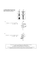
8–31. The drill is jammed in the wall and is subjected to the
torque and force shown. Determine the state of stress at
point A on the cross section of the drill bit at section a–a.
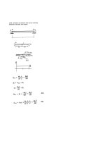
8–35. The block is subjected to the eccentric load shown.
Determine the normal stress developed at points A and B.
Neglect the weight of the block.
*8–32. The drill is jammed in the wall and is subjected to
the torque and force shown. Determine the state of stress at
point B on the cross section of the drill bit at section a–a.
*8–36. The block is subjected to the eccentric load shown.
Sketch the normal-stress distribution acting over the cross
section at section a–a. Neglect the weight of the block.
y
400 mm
150 kN
a 20 N ·m
100 mm
x
150 mm
a
a
C
125 mm
a
y
A
z
5 mm
3
A
B
5
4
150 N
B
Section a – a
Probs. 8–35/36
Probs. 8–31/32
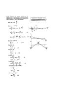
8–33. Determine the state of stress at point A when the
beam is subjected to the cable force of 4 kN. Indicate the
result as a differential volume element.
8–37. If the 75-kg man stands in the position shown,
determine the state of stress at point A on the cross section
Illustrations with
Vectors
Most of the diagrams
throughout the book are in
full-color art, and many
photorealistic illustrations
with vectors have been added.
These provide a strong
connection to the 3-D nature of
engineering. This also helps the
student to visualize and be
aware of the concepts behind
the question.
9
P r e fa c e
Once the beam has
been selected, the shea
r formula can then
to be sure the allow
be used
able shear stress is
not exceeded, t
Often this requirem
allow Ú VQ> It.
ent will not present
a problem; however
is “short” and supp
, if the beam
orts large concentr
ated loads, the shea
limitation may dicta
r-stress
te the size of the beam
.
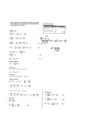
Steel Section
s. Most manufacture
d steel beams are prod
rolling a hot ingot
uced by
of steel until the desi
red shape is formed.
so-called rolled shap
These
es have properties
that are tabulated
American Institute
in the
of Steel Constru
ction (AISC) man
representative listin
ual. A
g of different cross sect
ions taken from this
given in Appendix
manual is
B.
their depth and mas
s per unit length; for
example, W460 * 68
indicates
unit length of 68 kg>m
, Fig. 11–4. For any
given selection, the
unit length, dimensi
mass per
ons, cross-sectional
area
, moment of inertia,
section modulus are
reported. Also inclu
and
ded is the radius of
which is a geometric
gyration, r,
property related to
the section’s buckling
This will be discusse
g strength.
d in Chapter 13.
Typical profile view
of a steel
wide-flange beam
15.4 mm
9.14 mm
459 mm
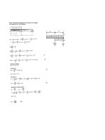
FOR
ENTER
A
154 mm
C
HEAR
7.5 S
OPEN T
HIN-W
ALLED
419
RS
MEMBE
The large shear force
that occu
ribution
curs
rs at the
W460 68
support of this steel
flow dist
beam can cause
e shear- distribution is
localized buckling of
with th
the beam
m’s
s to do
hen this t forces of Ff
’s flanges
ha
W
ts
or web. To avoid this,
b.
is
24
ltan
ts
a “stiffener” A is
ber tw
11–4 eb, Fig. 7–
emFig.
placed along the web
momen
give resu
on the m flanges and w
to maintain
s, it will g. 7–24c. If the couple
in stability.
yThe reas
ed
nel’s
web area
, Fi
Photographs
Many photographs are used
throughout the book to enhance
conceptual understanding and
explain how the principles of
mechanics of materials apply to
real-world situations.
▼
10
7
nc
e and
e chan
e web
r
unbala
along th over the flang of V = P in th
sible fo
A, the
respon
e
ed
e
t point
integrat nge and a forc
ed abou is seen to be ewed from th
m
m
su
fla
are
rces
rnal
hen vi
fo
te
es
w
in
rc
e
e
in each
is
fo
e
ng
activ
ockw
e fla
cl
re
th
is
e three
is
e
th
es
t
by
us
t
is
th
of
ted
beca
even
al tw
ue crea
7–24a,
he actu
r to pr
to
or torq e member. T
in Fig. ting. In orde is necessary
th
shown
is
as
t, it
,
en
eb
w
om
twisting the beam, as cause the tw
m
the
lanced
e from
front of m” forces Ff ncel the unba
distance
briu
e ca
centric
or
or
ec
e,
ef
P
“equili
er
an
Ff d =
cated
and th
int O lo quire π MA =
twisting
at a po
re
apply P Fig. 7–24d. We
Ff d
in
nter .
n
ow
=
sh
e
xural ce
P
er or fle ut twisting,
ear cent
ho
d the sh will bend wit shear center
lle
ca
is
am
the
ed
located
t, the be e location of
only us
int O so
is poin
t th
e comm
The po applied at th
often lis ctions that ar
books
P is
s se
nd
ays
os
w
ha
cr
al
n
l
When
wil
Desig
led beam
r center area. For
7–24e.
thin-wal
the shea
nal
riety of
no
ted that s cross-sectio
a,
25
no
for a va .
7–
be
ld
, Fig.
ber’
tice
is, it shou
a mem is applied at A nges for this
in prac
is analys
etry of
P
fla
ents
From th axis of symm tated 90° and the web and
em
el
e
in
is ro
an
in thes
has
lie on if the channel the shear flow e resultants
ember
e
e,
e
forc
ly, if a m
exampl ill occur sinc
ore the 25b. Obvious of a wide-flang
w
d theref
es
ax
e
es
twisting mmetrical, an about A, Fig. 7– , as in the case
of th
on
ry
ts
sy
ti
et
is
en
ec
m
case
sym
mom
inters
te zero
axes of
ith the
will crea ction with two ill coincide w
se
er w
a cross
ear cent
sh
e
th
beam,
ntroid).
(the ce
flects
beam de bove)
ilever
roid (a
is cant
how th ugh the cent ow).
el
ro
Notice
th
(b
er
ed
ad
cent
when lo h the shear
ug
and thro
P
P
Ff
Ff
A
A
V
P
2
A
V
P
2
(b)
(a)
25
Fig. 7–
P r e fa c e
Video Solutions. An invaluable resource in and out of the classroom,
▼
Reduces lecturers’ time spent
on repetitive explanation of
concepts and applications.
Flexible resource for students,
offering learning at a
comfortable pace
▼
Independent video replays
of a lecturer’s explanation
reinforces students’
understanding
▼
these complete solution walkthroughs of representative problems and
applications from each chapter offer fully worked solutions, self-paced
instruction, and 24/7 accessibility via the companion Website. Lecturers
and students can harness this resource to gain independent exposure to a
wide range of examples by applying formulae to actual structures.
11
12
P r e fa c e
CoNteNts
The subject matter is organized into 14 chapters. Chapter 1 begins with a
review of the important concepts of statics, followed by a formal definition
of both normal and shear stress, and a discussion of normal stress in axially
loaded members and average shear stress caused by direct shear.
In Chapter 2 normal and shear strain are defined, and in Chapter 3 a
discussion of some of the important mechanical properties of materials is
given. Separate treatments of axial load, torsion, and bending are presented
in Chapters 4, 5, and 6, respectively. In each of these chapters, both linearelastic and plastic behavior of the material covered in the previous chapters,
where the state of stress results from combined loadings. In Chapter 9 the
concepts for transforming multiaxial states of stress are presented. In a
similar manner, Chapter 10 discusses the methods for strain transformation,
including the application of various theories of failure. Chapter 11 provides
a means for a further summary and review of previous material by covering
design applications of beams and shafts. In Chapter 12 various methods for
computing deflections of beams and shafts are covered. Also included is a
discussion for finding the reactions on these members if they are statically
indeterminate. Chapter 13 provides a discussion of column buckling, and
lastly, in Chapter 14 the problem of impact and the application of various
energy methods for computing deflections are considered.
Sections of the book that contain more advanced material are indicated
by a star (*). Time permitting, some of these topics may be included in
the course. Furthermore, this material provides a suitable reference for
basic principles when it is covered in other courses, and it can be used as
a basis for assigning special projects.
Alternative Method of Coverage. Some instructors prefer to cover
stress and strain transformations first, before discussing specific applications
of axial load, torsion, bending, and shear. One possible method for doing this
would be first to cover stress and its transformation, Chapter 1 and Chapter 9,
followed by strain and its transformation, Chapter 2 and the first part of
Chapter 10. The discussion and example problems in these later chapters have
been styled so that this is possible. Also, the problem sets have been subdivided
so that this material can be covered without prior knowledge of the intervening
chapters. Chapters 3 through 8 can then be covered with no loss in continuity.
aCkNowledgmeNts
Over the years, this text has been shaped by the suggestions and comments
of many of my colleagues in the teaching profession. Their encouragement
and willingness to provide constructive criticism are very much appreciated
and it is hoped that they will accept this anonymous recognition. A note
of thanks is given to the reviewers.
S. Apple, Arkansas Tech University
A. Bazar, University of California, Fullerton
P r e fa c e
M. Hughes, Auburn University
R. Jackson, Auburn University
E. Tezak, Alfred State College
H. Zhao, Clemson University
There are a few people that I feel deserve particular recognition. A longtime friend and associate, Kai Beng Yap, was of great help to me in
preparing the problem solutions. A special note of thanks also goes to
Kurt Norlin in this regard. During the production process I am thankful
for the assistance of Rose Kernan, my production editor for many years,
and to my wife, Conny, for her help in proofreading and typing, that was
needed to prepare the manuscript for publication.
I would also like to thank all my students who have used the previous
edition and have made comments to improve its contents; including all
those in the teaching profession who have taken the time to e-mail me
their comments, but in particular G. H. Nazari.
I would greatly appreciate hearing from you if at any time you have
any comments or suggestions regarding the contents of this edition.
Russell Charles Hibbeler
global editioN
The publishers would like to thank the following for their contribution to
the Global Edition:
Contributor for the Tenth Edition in SI Units
Kai Beng Yap is currently a registered professional engineer who works
in Malaysia. He has BS and MS degrees in civil engineering from the
University of Louisiana, Lafayette, Louisiana; and has done further
graduate work at Virginia Tech in Blacksburg, Virginia. He has taught at
the University of Louisiana and worked as an engineering consultant in
the areas of structural analysis and design, and the associated infrastructure.
Reviewers for the Tenth Edition in SI Units
Imad Abou-Hayt, Aalborg University of Copenhagen
Weena Lokuge, University of Southern Queensland
Samit Ray Chaudhuri, Indian Institute of Technology Kanpur
Contributors for Earlier SI Editions
Pearson would like to thank S. C. Fan, who has retired from Nanyang
Technological University, Singapore, and K. S. Vijay Sekar, who teaches
in SSN College of Engineering, India, for their work on the 8th and 9th
SI editions of this title, respectively.
13
your work...
your
youranswer
answer
feedback
feedback
0.000844
0.000844mm3 3
®®
16
P r e fa c e
resourCes for iNstruCtors
• MasteringEngineering. This online Tutorial Homework program allows
you to integrate dynamic homework with automatic grading and adaptive
tutoring. MasteringEngineering allows you to easily track the performance
of your entire class on an assignment-by-assignment basis, or the detailed
work of an individual student.
• Instructor’s Solutions Manual. An instructor’s solutions manual was
prepared by the author. The manual includes homework assignment lists
and was also checked as part of the accuracy checking program. The
Instructor Solutions Manual is available at www.pearsonglobaleditions.com.
• Presentation Resources. All art from the text is available in PowerPoint
slide and JPEG format. These files are available for download at www
.pearsonglobaleditions.com. If you are in need of a login and password for
this site, please contact your local Pearson representative.
• Video Solutions. Developed primarily by Professor Edward Berger,
Purdue University, video solutions located on the companion Website
offer step-by-step solution walkthroughs of representative homework
problems from each section of the text. Make efficient use of class time
and office hours by showing students the complete and concise problem
solving approaches that they can access anytime and view at their own
pace. The videos are designed to be a flexible resource to be used however
each instructor and student prefers. A valuable tutorial resource, the
videos are also helpful for student self-evaluation as students can pause
the videos to check their understanding and work alongside the video.
resourCes for studeNts
• Mastering Engineering. Tutorial homework problems emulate the
instructor’s office-hour environment, guiding students through engineering
concepts with self-paced individualized coaching. These in-depth tutorial
homework problems are designed to coach students with feedback specific
to their errors and optional hints that break problems down into simpler steps.
• Companion Website—The companion Website, located at
www.pearsonglobaleditions.com/hibbeler, includes opportunities for
practice and review, including access to video solutions offering complete,
step-by-step solution walkthroughs of representative homework problems
from various sections of the text.
C O NTE NTS
1
1.1
1.2
1.3
1.4
1.5
1.6
1.7
2
2.1
2.2
21
Stress
Chapter Objectives 21
Introduction 21
Equilibrium of a Deformable Body 22
Stress 40
Average Normal Stress in an Axially
Loaded Bar 42
Average Shear Stress 50
Allowable Stress Design 64
Limit State Design 66
4
4.1
4.2
4.3
4.4
4.5
4.6
4.7
*4.8
*4.9
3.1
3.2
3.3
3.4
3.5
3.6
*3.7
Mechanical Properties
of Materials
Chapter Objectives 141
Saint-Venant’s Principle 141
Elastic Deformation of an Axially Loaded
Member 143
Principle of Superposition 158
Statically Indeterminate Axially Loaded
Members 158
The Force Method of Analysis for Axially
Loaded Members 165
Thermal Stress 173
Stress Concentrations 180
Inelastic Axial Deformation 183
Residual Stress 185
87
5
3
141
87
Strain
Chapter Objectives
Deformation 87
Strain 88
Axial Load
Chapter Objectives 103
The Tension and Compression Test 103
The Stress–Strain Diagram 105
Stress–Strain Behavior of Ductile and
Brittle Materials 109
Strain Energy 113
Poisson’s Ratio 124
The Shear Stress–Strain Diagram 126
Failure of Materials Due to Creep
and Fatigue 129
201
Chapter Objectives 201
Torsional Deformation of a Circular
Shaft 201
5.2 The Torsion Formula 204
5.3 Power Transmission 212
5.4 Angle of Twist 224
5.5 Statically Indeterminate Torque-Loaded
Members 240
*5.6 Solid Noncircular Shafts 247
*5.7 Thin-Walled Tubes Having Closed Cross
Sections 250
5.8 Stress Concentration 260
*5.9 Inelastic Torsion 263
*5.10 Residual Stress 265
5.1
103
Torsion
18
contents
6
Bending
281
Chapter Objectives 281
Shear and Moment Diagrams 281
Graphical Method for Constructing Shear
and Moment Diagrams 288
6.3 Bending Deformation of a Straight
Member 307
6.4 The Flexure Formula 311
6.5 Unsymmetric Bending 328
*6.6 Composite Beams 338
*6.7 Reinforced Concrete Beams 341
*6.8 Curved Beams 345
6.9 Stress Concentrations 352
*6.10 Inelastic Bending 362
6.1
6.2
9
9.1
9.2
9.3
9.4
9.5
10
7
7.1
7.2
7.3
7.4
*7.5
8
8.1
8.2
Transverse Shear
385
Chapter Objectives 385
Shear in Straight Members 385
The Shear Formula 386
Shear Flow in Built-Up Members 404
Shear Flow in Thin-Walled Members 413
Shear Center for Open Thin-Walled
Members 418
Combined Loadings
Chapter Objectives 431
Thin-Walled Pressure Vessels 431
State of Stress Caused by Combined
Loadings 438
431
10.1
10.2
*10.3
*10.4
10.5
10.6
*10.7
11
Stress Transformation
463
Chapter Objectives 463
Plane-Stress Transformation 463
General Equations of Plane-Stress
Transformation 468
Principal Stresses and Maximum In-Plane
Shear Stress 471
Mohr’s Circle—Plane Stress 487
Absolute Maximum Shear Stress 499
Strain Transformation
511
Chapter Objectives 511
Plane Strain 511
General Equations of Plane-Strain
Transformation 512
Mohr’s Circle—Plane Strain 520
Absolute Maximum Shear Strain 528
Strain Rosettes 530
Material Property Relationships 534
Theories of Failure 546
Design of Beams and
Shafts
Chapter Objectives 563
11.1 Basis for Beam Design 563
11.2 Prismatic Beam Design 566
*11.3 Fully Stressed Beams 580
*11.4 Shaft Design 584
563
19
contents
12
12.1
12.2
*12.3
*12.4
12.5
12.6
12.7
*12.8
12.9
13
13.1
13.2
13.3
*13.4
*13.5
*13.6
*13.7
Deflection of Beams
and Shafts
595
Chapter Objectives 595
The Elastic Curve 595
Slope and Displacement by
Integration 599
Discontinuity Functions 617
Slope and Displacement by the
Moment-Area Method 629
Method of Superposition 644
Statically Indeterminate Beams
and Shafts 652
Statically Indeterminate Beams and
Shafts—Method of Integration 653
Statically Indeterminate Beams and
Shafts—Moment-Area Method 658
Statically Indeterminate Beams and
Shafts—Method of Superposition 664
Buckling of Columns
Chapter Objectives 683
Critical Load 683
Ideal Column with Pin Supports 686
Columns Having Various Types of
Supports 692
The Secant Formula 704
Inelastic Buckling 710
Design of Columns for Concentric
Loading 718
Design of Columns for Eccentric
Loading 728
683
14
Energy Methods
741
Chapter Objectives 741
External Work and Strain Energy 741
Elastic Strain Energy for Various Types
of Loading 746
14.3
Conservation of Energy 759
14.4
Impact Loading 766
*14.5
Principle of Virtual Work 777
*14.6
Method of Virtual Forces Applied
to Trusses 780
*14.7
Method of Virtual Forces Applied
to Beams 788
*14.8
Castigliano’s Theorem 797
*14.9
Castigliano’s Theorem Applied
to Trusses 799
*14.10 Castigliano’s Theorem Applied
to Beams 802
14.1
14.2
Appendix
A
B
C
Geometric Properties of an Area 810
Geometric Properties of Structural
Shapes 824
Slopes and Deflections of Beams 829
Solutions and Answers for
Preliminary Problems 831
Fundamental Problems Partial
Solutions and Answers 841
Selected Answers
Index
883
863
Chapter
1
(© alexskopje/Fotolia)
The bolts used for the connections of this steel framework are subjected to stress.
In this chapter we will discuss how engineers design these connections and their
fasteners.
StReSS
Chapter OBJeCtIVeS
n
In this chapter we will review some of the important principles of
statics and show how they are used to determine the internal
resultant loadings in a body. Afterwards the concepts of normal and
shear stress will be introduced, and specific applications of the
analysis and design of members subjected to an axial load or direct
shear will be discussed.
1.1
IntroductIon
Mechanics of materials is a branch of mechanics that studies the internal
effects of stress and strain in a solid body. Stress is associated with the
strength of the material from which the body is made, while strain is a
measure of the deformation of the body. A thorough understanding of
the fundamentals of this subject is of vital importance for the design of
any machine or structure, because many of the formulas and rules
of design cited in engineering codes are based upon the principles of
this subject.
21
22
Chapter 1
StreSS
Historical Development.
1
The origin of mechanics of materials
dates back to the beginning of the seventeenth century, when Galileo
Galilei performed experiments to study the effects of loads on rods and
beams made of various materials. However, it was not until the beginning
of the nineteenth century when experimental methods for testing
materials were vastly improved. At that time many experimental and
theoretical studies in this subject were undertaken, primarily in France,
by such notables as Saint-Venant, Poisson, Lamé, and Navier.
Through the years, after many fundamental problems had been solved,
it became necessary to use advanced mathematical and computer
techniques to solve more complex problems. As a result, mechanics of
materials has expanded into other areas of mechanics, such as the theory
of elasticity and the theory of plasticity.
1.2
EquIlIbrIum of a dEformablE
body
Since statics plays an important role in both the development and
application of mechanics of materials, it is very important to have a good
grasp of its fundamentals. For this reason we will now review some of the
main principles of statics that will be used throughout the text.
Loads. A body can be subjected to both surface loads and body
forces. Surface loads that act on a small area of contact are reported by
concentrated forces, while distributed loadings act over a larger surface
area of the body. When the loading is coplanar, as in Fig. 1–1a, then a
resultant force FR of a distributed loading is equal to the area under the
distributed loading diagram, and this resultant acts through the geometric
center or centroid of this area.
700 N
FR 400 N
200 N/m
B
A
1m
1m
1m
(a)
Fig. 1–1
1.5 m